Embed Size (px)
Citation preview

Future Circular Collider Study
Volume 4 - The High-Energy LHC (HE-LHC)
Conceptual Design Report
P R E P R I N TV0.11, 8 November 2018
NOTICE: Parts of this draft document are not yet tailored to the HE-LHCneeds and may still refer to the FCC-hh collider scenario.
HE-LHC Conceptual Design Report (V0.11, 8 November 2018)
Volume EditorsMichael Benedikt, Mar Capeans, Francesco Cerutti, Brennan Goddard, Johannes Gutleber,Jose-Miguel Jimenez, Michelangelo Mangano, Volker Mertens, John Osborne, Thomas Otto, John Poole,Werner Riegler, Laurent Tavian, Davide Tommasini, Frank Zimmermann.
Cover DesignPanagiotis Charitos and Johannes Gutleber
AcknowledgementsWe would like to thank the International Advisory Committee members:G. Dissertori, ETH Zürich, Switzerland; A. Parker, University of Cambridge, UK; C. Quigg, Fermilab,USA; M. Diemoz, INFN, Italy; G. Herten, University Freiburg, Germany; V. Egorychev, ITEP, Russia;R. Assmann, DESY, Germany; C. Biscari, CELLS-ALBA, Spain; W. Fischer, BNL, USA; V. Shilt-sev, Fermilab, USA; J. Minervini, MIT, USA; A. Mosnier, CEA, France; A. Yamamoto, KEK, Japan;M. Ross, SLAC, USA; M. Seidel, PSI, Switzerland; P. Lebrun, JUAS, France; T. Watson, ITER, IEIOand the International Steering Committee members:P. Chomaz, CEA, France; E. Colby, SLAC, USA; J. Womersley, ESSS, Sweden; S. Asai, University ofTokyo, Japan; F. Bordry, CERN, IEIO; P. Campana, INFN, Italy; G. Dissertori, ETH Zürich, Switzer-land; E. Elsen, CERN, IEIO; A. Lankford, UCI, USA; L. Rivkin, PSI, Switzerlandfor the continued and careful reviewing that helped to successfully complete this conceptual design re-port.
The editors wish to thank all the scientific, engineering and technical personnel, the students andearly stage researchers and all associated member of personnel involved in the investigations, designsand prototyping for their invaluable contributions that made this work possible.
We also want to express our thanks to the administration officers who prepared the ground andcreated a framework in which this work could be carried out efficiently. The FCC study managementteam thanks in particular John Poole for his enthusiastic dedication during the editing phase, contribut-ing significantly to deliver a coherent, consistent and readable set of report volumes. Finally, we wish tothank the CERN management for their strong support and encouragement.
The research, which led to this publication has received funding from the European Union’s Hori-zon 2020 research and innovation programme under the grant numbers 654305 (EuroCirCol), 764879(EASITrain), 730871 (ARIES) and 777563 (RI-Paths). The information herein only reflects the viewsof its authors and the European Commission is not responsible for any use that may be made of theinformation.
Trademark notice: All trademarks appearing in this report are acknowledged as such.
iiP R E P R I N T
CERN Yellow Reports: Monographs
Published by CERN, CH-1211 Geneva 23, SwitzerlandPreprint, December 2018
xxx-xx-xxxx-xxx-x (paperback)ISBN xxx-xx-xxxx-xxx-x (PDF)ISSN xxxx-xxxx (Print)ISSN xxxx-xxxx (Online)DOI https://doi.org/xx.xxxxx/CYRM-2018-xxx
Accepted for publication by the CERN Report Editorial Board (CREB) on xx MONTH 2018Available online at https://doi.org/xx.xxxxx/CYRM-2018-xxx
This book was edited with the Overleaf.com collaborative writing and publishing system. Typesettingand final print preparation was performed using pdfTEX3.14159265-2.6-1.40.17
Copyright CERN, 2018, unless otherwise specifiedCreative Commons Attribution 4.0
Knowledge transfer is an integral part of CERN’s mission.CERN publishes this volume Open Access under the Creative Commons Attribution 4.0 license(http://creativecommons.org/licenses/by/4.0/) in order to permit its wide dissemination anduse. The submission of a contribution to a CERN Yellow Reports series shall be deemed to constitutethe contributor’s agreement to this copyright and license statement. Contributors are requested to obtainany clearances that may be necessary for this purpose.
This volume is indexed in: CERN Document Server (CDS), INSPIRE.
This report should be cited as:Future Circular Collider Study. Volume 2: The Lepton Collider (FCC-ee). Conceptual Design Report,edited by Michael Benedikt, Mar Capeans, Francesco Cerutti, Brennan Goddard, Johannes Gutleber,Jose-Miguel Jimenez, Michelangelo Mangano, Volker Mertens, John Osborne, Thomas Otto, John Poole,Werner Riegler, Laurent Tavian, Davide Tommasini, Frank Zimmermann.CERN Yellow Reports: Monographs, Vol. x/2018, CERN-2018-xxx-M (CERN, Geneva, 2018).https://doi.org/xx.xxxx/CYRM-2018-xxx
P R E P R I N Tiii

HE-LHC Conceptual Design Report (V0.11, 8 November 2018)
ivP R E P R I N T

FCC Collaboration
This section lists the persons, who contributed to the FCC study.
v

HE-LHC Conceptual Design Report (V0.11, 8 November 2018)
viP R E P R I N T

Executive Summary
This is the executive summary of the report.
vii
HE-LHC Conceptual Design Report (V0.11, 8 November 2018)
Contents
FCC Collaboration v
Executive Summary vii
1 Physics Opportunities and Reach 11.1 Introduction . . . . . . . . . . . . . . . . . . . . . . . . . . . . . . . . . . . . . . . . . . 1
1.2 The Boundary Conditions for the HE-LHC Physics Studies . . . . . . . . . . . . . . . . . 2
1.3 The Discovery Reach Potential of HE-LHC . . . . . . . . . . . . . . . . . . . . . . . . . . 2
1.3.1 Supersymmetry . . . . . . . . . . . . . . . . . . . . . . . . . . . . . . . . . . . . . . . 3
1.3.2 WIMP searches . . . . . . . . . . . . . . . . . . . . . . . . . . . . . . . . . . . . . . . 3
1.3.3 Resonance searches . . . . . . . . . . . . . . . . . . . . . . . . . . . . . . . . . . . . . 4
1.4 Measurements of Higgs Properties . . . . . . . . . . . . . . . . . . . . . . . . . . . . . . 4
1.5 Further Exploration of LHC Discoveries at HE-LHC . . . . . . . . . . . . . . . . . . . . . 8
1.5.1 Characterisation of a Z′ gauge boson . . . . . . . . . . . . . . . . . . . . . . . . . . . . 8
1.5.2 Flavour anomalies . . . . . . . . . . . . . . . . . . . . . . . . . . . . . . . . . . . . . . 10
2 Collider Design and Performance 112.1 Requirements and Design Considerations . . . . . . . . . . . . . . . . . . . . . . . . . . . 11
2.2 Parameter Choices . . . . . . . . . . . . . . . . . . . . . . . . . . . . . . . . . . . . . . . 12
2.3 Design Challenges and Approaches . . . . . . . . . . . . . . . . . . . . . . . . . . . . . . 12
2.3.1 Synchrotron Radiation . . . . . . . . . . . . . . . . . . . . . . . . . . . . . . . . . . . 12
2.3.2 Dynamic and Physical Aperture at Injection . . . . . . . . . . . . . . . . . . . . . . . . 12
2.3.3 Event Pile-Up . . . . . . . . . . . . . . . . . . . . . . . . . . . . . . . . . . . . . . . . 18
2.4 Optics Design and Beam Dynamics . . . . . . . . . . . . . . . . . . . . . . . . . . . . . . 18
2.4.1 Arc Optics, Layout and Physical Aperture . . . . . . . . . . . . . . . . . . . . . . . . . 18
2.4.2 Optics and Shielding in the Experiment Insertions . . . . . . . . . . . . . . . . . . . . . 23
2.4.3 RF and Diagnostics Insertion . . . . . . . . . . . . . . . . . . . . . . . . . . . . . . . . 28
2.4.4 Collimation . . . . . . . . . . . . . . . . . . . . . . . . . . . . . . . . . . . . . . . . . 28
2.4.5 Extraction . . . . . . . . . . . . . . . . . . . . . . . . . . . . . . . . . . . . . . . . . . 31
2.4.6 Injection . . . . . . . . . . . . . . . . . . . . . . . . . . . . . . . . . . . . . . . . . . . 33
2.4.7 Longitudinal Parameters and RF Profile on the Ramp . . . . . . . . . . . . . . . . . . . 33
2.4.8 Beam-Beam Effects and Crossing Angle . . . . . . . . . . . . . . . . . . . . . . . . . . 36
2.4.9 Space Charge, Bunch-to-Bunch Tune Variation, Intrabeam Scattering, Touschek Effect . 38
2.4.10 Impedance Model . . . . . . . . . . . . . . . . . . . . . . . . . . . . . . . . . . . . . . 38
2.4.11 Single-Beam Coherent Instabilities . . . . . . . . . . . . . . . . . . . . . . . . . . . . . 41
2.4.12 Electron Cloud . . . . . . . . . . . . . . . . . . . . . . . . . . . . . . . . . . . . . . . 43
2.5 Operation and Performance . . . . . . . . . . . . . . . . . . . . . . . . . . . . . . . . . . 45
2.5.1 Leveling at Constant IP Divergence . . . . . . . . . . . . . . . . . . . . . . . . . . . . . 47
2.6 Heavy Ion Operation . . . . . . . . . . . . . . . . . . . . . . . . . . . . . . . . . . . . . . 48
2.7 Lepton-Hadron Operation . . . . . . . . . . . . . . . . . . . . . . . . . . . . . . . . . . . 49
viiiP R E P R I N T
3 Collider Technical Systems 533.1 Overview . . . . . . . . . . . . . . . . . . . . . . . . . . . . . . . . . . . . . . . . . . . . 53
3.2 Main Magnet System . . . . . . . . . . . . . . . . . . . . . . . . . . . . . . . . . . . . . 53
3.2.1 Introduction . . . . . . . . . . . . . . . . . . . . . . . . . . . . . . . . . . . . . . . . . 53
3.2.2 Superconducting Main Dipole . . . . . . . . . . . . . . . . . . . . . . . . . . . . . . . 53
3.2.3 Field Quality . . . . . . . . . . . . . . . . . . . . . . . . . . . . . . . . . . . . . . . . 57
3.2.4 Magnet Protection . . . . . . . . . . . . . . . . . . . . . . . . . . . . . . . . . . . . . 58
3.2.5 Other Design Options . . . . . . . . . . . . . . . . . . . . . . . . . . . . . . . . . . . . 58
3.2.6 Low Temperature Superconductors . . . . . . . . . . . . . . . . . . . . . . . . . . . . . 60
3.2.7 Superconducting Main Quadrupole . . . . . . . . . . . . . . . . . . . . . . . . . . . . . 60
3.2.8 Other Magnets in the Arcs . . . . . . . . . . . . . . . . . . . . . . . . . . . . . . . . . 61
3.2.9 Low-Beta Quadrupoles and Separation Dipoles . . . . . . . . . . . . . . . . . . . . . . 61
3.2.10 Other Magnets . . . . . . . . . . . . . . . . . . . . . . . . . . . . . . . . . . . . . . . . 61
3.3 Cryogenic Beam Vacuum System . . . . . . . . . . . . . . . . . . . . . . . . . . . . . . . 62
3.3.1 Overview . . . . . . . . . . . . . . . . . . . . . . . . . . . . . . . . . . . . . . . . . . 62
3.3.2 Beamscreen . . . . . . . . . . . . . . . . . . . . . . . . . . . . . . . . . . . . . . . . . 63
3.3.3 Vacuum . . . . . . . . . . . . . . . . . . . . . . . . . . . . . . . . . . . . . . . . . . . 67
3.4 Radiofrequency System . . . . . . . . . . . . . . . . . . . . . . . . . . . . . . . . . . . . 68
3.4.1 Overview . . . . . . . . . . . . . . . . . . . . . . . . . . . . . . . . . . . . . . . . . . 68
3.4.2 Superconducting Accelerating Cavities . . . . . . . . . . . . . . . . . . . . . . . . . . . 68
3.4.3 Crab Cavities . . . . . . . . . . . . . . . . . . . . . . . . . . . . . . . . . . . . . . . . 69
3.4.4 RF power generation . . . . . . . . . . . . . . . . . . . . . . . . . . . . . . . . . . . . 69
3.4.5 Low-Level RF . . . . . . . . . . . . . . . . . . . . . . . . . . . . . . . . . . . . . . . . 70
3.5 Beam Transfer Systems . . . . . . . . . . . . . . . . . . . . . . . . . . . . . . . . . . . . 71
3.5.1 Overview . . . . . . . . . . . . . . . . . . . . . . . . . . . . . . . . . . . . . . . . . . 71
3.5.2 HE-LHC injection system . . . . . . . . . . . . . . . . . . . . . . . . . . . . . . . . . . 71
3.5.3 HE-LHC beam dump system . . . . . . . . . . . . . . . . . . . . . . . . . . . . . . . . 72
3.5.4 Dilution and dump . . . . . . . . . . . . . . . . . . . . . . . . . . . . . . . . . . . . . 75
3.5.5 Conclusion . . . . . . . . . . . . . . . . . . . . . . . . . . . . . . . . . . . . . . . . . 76
3.6 Beam Diagnostics . . . . . . . . . . . . . . . . . . . . . . . . . . . . . . . . . . . . . . . 76
3.6.1 Requirements and Concepts . . . . . . . . . . . . . . . . . . . . . . . . . . . . . . . . . 76
3.6.2 Beam Position Monitoring . . . . . . . . . . . . . . . . . . . . . . . . . . . . . . . . . 77
3.6.3 Beam Loss Monitoring . . . . . . . . . . . . . . . . . . . . . . . . . . . . . . . . . . . 77
3.6.4 Beam Current and Intensity Measurements . . . . . . . . . . . . . . . . . . . . . . . . . 77
3.6.5 Tune, Chromaticity and Coupling . . . . . . . . . . . . . . . . . . . . . . . . . . . . . . 78
3.6.6 Transverse Profile Measurements . . . . . . . . . . . . . . . . . . . . . . . . . . . . . . 78
3.7 Element Support, Survey and Alignment Requirements, and Concepts . . . . . . . . . . . 78
3.8 Architecture and Powering of Magnet Circuits . . . . . . . . . . . . . . . . . . . . . . . . 79
3.8.1 Power Converters for Magnet Powering . . . . . . . . . . . . . . . . . . . . . . . . . . 80
3.8.2 Energy Storage in Power Converters . . . . . . . . . . . . . . . . . . . . . . . . . . . . 82
3.9 Machine Protection Concepts . . . . . . . . . . . . . . . . . . . . . . . . . . . . . . . . . 83
P R E P R I N Tix
HE-LHC Conceptual Design Report (V0.11, 8 November 2018)
3.10 Controls Requirements and Concepts . . . . . . . . . . . . . . . . . . . . . . . . . . . . . 84
3.11 Radiation Environment . . . . . . . . . . . . . . . . . . . . . . . . . . . . . . . . . . . . 86
3.11.1 Introduction . . . . . . . . . . . . . . . . . . . . . . . . . . . . . . . . . . . . . . . . . 86
3.11.2 Reference Radiation Levels . . . . . . . . . . . . . . . . . . . . . . . . . . . . . . . . . 86
3.11.3 Radiation Hardness . . . . . . . . . . . . . . . . . . . . . . . . . . . . . . . . . . . . . 87
4 Civil Engineering 894.1 Requirements and Considerations for Upgrade of the Existing Infrastructure . . . . . . . . 89
4.2 Lifetime of the Existing Tunnel Infrastructure . . . . . . . . . . . . . . . . . . . . . . . . 90
4.3 New civil engineering infrastructure . . . . . . . . . . . . . . . . . . . . . . . . . . . . . 90
4.3.1 Underground structures . . . . . . . . . . . . . . . . . . . . . . . . . . . . . . . . . . . 90
4.3.2 Surface Points . . . . . . . . . . . . . . . . . . . . . . . . . . . . . . . . . . . . . . . . 93
4.4 Tunnel enlargements . . . . . . . . . . . . . . . . . . . . . . . . . . . . . . . . . . . . . . 93
4.5 Sector 3-4 refurbishment . . . . . . . . . . . . . . . . . . . . . . . . . . . . . . . . . . . 94
5 Technical Infrastructures 995.1 Requirements and Design Considerations . . . . . . . . . . . . . . . . . . . . . . . . . . . 99
5.2 Piped Utilities . . . . . . . . . . . . . . . . . . . . . . . . . . . . . . . . . . . . . . . . . 99
5.2.1 Introduction . . . . . . . . . . . . . . . . . . . . . . . . . . . . . . . . . . . . . . . . . 99
5.2.2 Water Cooling Plants . . . . . . . . . . . . . . . . . . . . . . . . . . . . . . . . . . . . 100
5.2.3 Operational Parameters . . . . . . . . . . . . . . . . . . . . . . . . . . . . . . . . . . . 100
5.2.4 Chilled Water . . . . . . . . . . . . . . . . . . . . . . . . . . . . . . . . . . . . . . . . 101
5.2.5 Drinking Water . . . . . . . . . . . . . . . . . . . . . . . . . . . . . . . . . . . . . . . 102
5.2.6 Raw Water . . . . . . . . . . . . . . . . . . . . . . . . . . . . . . . . . . . . . . . . . . 103
5.2.7 Fire Fighting Network . . . . . . . . . . . . . . . . . . . . . . . . . . . . . . . . . . . . 103
5.2.8 Reject Water . . . . . . . . . . . . . . . . . . . . . . . . . . . . . . . . . . . . . . . . . 103
5.2.9 Compressed Air . . . . . . . . . . . . . . . . . . . . . . . . . . . . . . . . . . . . . . . 104
5.3 Heating, Ventilation, Air Condition, Cooling . . . . . . . . . . . . . . . . . . . . . . . . . 104
5.3.1 Design . . . . . . . . . . . . . . . . . . . . . . . . . . . . . . . . . . . . . . . . . . . . 104
5.3.2 Indoor conditions . . . . . . . . . . . . . . . . . . . . . . . . . . . . . . . . . . . . . . 104
5.3.3 Ventilation of Underground Areas . . . . . . . . . . . . . . . . . . . . . . . . . . . . . 104
5.3.4 Machine Tunnel . . . . . . . . . . . . . . . . . . . . . . . . . . . . . . . . . . . . . . . 105
5.3.5 Experiment Caverns . . . . . . . . . . . . . . . . . . . . . . . . . . . . . . . . . . . . . 106
5.3.6 Other Areas . . . . . . . . . . . . . . . . . . . . . . . . . . . . . . . . . . . . . . . . . 107
5.3.7 Operating Modes . . . . . . . . . . . . . . . . . . . . . . . . . . . . . . . . . . . . . . 107
5.3.8 Working Parameters . . . . . . . . . . . . . . . . . . . . . . . . . . . . . . . . . . . . . 107
5.3.9 Ventilation of Surface Buildings . . . . . . . . . . . . . . . . . . . . . . . . . . . . . . 108
5.3.10 Safety . . . . . . . . . . . . . . . . . . . . . . . . . . . . . . . . . . . . . . . . . . . . 108
5.4 Electricity Distribution . . . . . . . . . . . . . . . . . . . . . . . . . . . . . . . . . . . . 108
5.4.1 Conceptual Layout . . . . . . . . . . . . . . . . . . . . . . . . . . . . . . . . . . . . . 108
5.4.2 Source of Electrical Energy . . . . . . . . . . . . . . . . . . . . . . . . . . . . . . . . . 108
5.4.3 Transmission Network Topology . . . . . . . . . . . . . . . . . . . . . . . . . . . . . . 109
xP R E P R I N T
5.4.4 Distribution Network Topology . . . . . . . . . . . . . . . . . . . . . . . . . . . . . . . 110
5.4.5 Power Quality and Transient Voltage Dip Mitigation . . . . . . . . . . . . . . . . . . . . 110
5.5 Emergency Power . . . . . . . . . . . . . . . . . . . . . . . . . . . . . . . . . . . . . . . 112
5.6 Cryogenic System . . . . . . . . . . . . . . . . . . . . . . . . . . . . . . . . . . . . . . . 114
5.6.1 Overview . . . . . . . . . . . . . . . . . . . . . . . . . . . . . . . . . . . . . . . . . . 114
5.6.2 Proximity Cryogenics and Heat Loads . . . . . . . . . . . . . . . . . . . . . . . . . . . 116
5.6.3 Cryogenic Plants . . . . . . . . . . . . . . . . . . . . . . . . . . . . . . . . . . . . . . 119
5.6.4 Cryogen Inventory and Storage . . . . . . . . . . . . . . . . . . . . . . . . . . . . . . . 120
5.7 Equipment Transport and Handling . . . . . . . . . . . . . . . . . . . . . . . . . . . . . . 121
5.8 Personnel Transport . . . . . . . . . . . . . . . . . . . . . . . . . . . . . . . . . . . . . . 122
5.9 Geodesy, Survey and Alignment . . . . . . . . . . . . . . . . . . . . . . . . . . . . . . . 122
5.9.1 Alignment Tolerances . . . . . . . . . . . . . . . . . . . . . . . . . . . . . . . . . . . . 122
5.9.2 Geodesy . . . . . . . . . . . . . . . . . . . . . . . . . . . . . . . . . . . . . . . . . . . 122
5.9.3 Metrological Aspects . . . . . . . . . . . . . . . . . . . . . . . . . . . . . . . . . . . . 123
5.9.4 Alignment of the Accelerator Components . . . . . . . . . . . . . . . . . . . . . . . . . 124
5.9.5 Interaction Regions and Collimators Areas . . . . . . . . . . . . . . . . . . . . . . . . . 124
5.9.6 Experiments . . . . . . . . . . . . . . . . . . . . . . . . . . . . . . . . . . . . . . . . . 124
5.10 Communications, Computing and Data Services . . . . . . . . . . . . . . . . . . . . . . . 124
5.11 Safety and Access Management Systems . . . . . . . . . . . . . . . . . . . . . . . . . . . 127
6 Injector Scenarios 1316.1 Requirements and Basic Assumptions . . . . . . . . . . . . . . . . . . . . . . . . . . . . . 131
6.2 Superconducting SPS as 1.3 TeV HEB . . . . . . . . . . . . . . . . . . . . . . . . . . . . 132
6.3 Summary . . . . . . . . . . . . . . . . . . . . . . . . . . . . . . . . . . . . . . . . . . . . 135
7 Experiments and Detectors 1377.1 Detector Considerations . . . . . . . . . . . . . . . . . . . . . . . . . . . . . . . . . . . . 137
8 Safety 1418.1 Safety Policy and Regulatory Framework . . . . . . . . . . . . . . . . . . . . . . . . . . . 141
8.1.1 Legal Context of CERN . . . . . . . . . . . . . . . . . . . . . . . . . . . . . . . . . . . 141
8.1.2 Hazard Register and Safety Performance Based Design . . . . . . . . . . . . . . . . . . 141
8.2 Occupational Health and Safety . . . . . . . . . . . . . . . . . . . . . . . . . . . . . . . . 142
8.2.1 Fire Hazard . . . . . . . . . . . . . . . . . . . . . . . . . . . . . . . . . . . . . . . . . 142
8.2.2 Oxygen Deficiency Hazard (ODH) . . . . . . . . . . . . . . . . . . . . . . . . . . . . . 143
8.3 Radiation Protection . . . . . . . . . . . . . . . . . . . . . . . . . . . . . . . . . . . . . . 146
8.3.1 Particle Beam Operation . . . . . . . . . . . . . . . . . . . . . . . . . . . . . . . . . . 146
8.3.2 Activation of Solids . . . . . . . . . . . . . . . . . . . . . . . . . . . . . . . . . . . . . 146
8.3.3 Activated or Contaminated Liquids . . . . . . . . . . . . . . . . . . . . . . . . . . . . . 147
8.3.4 Activated or Radioactive Gases and Radioactive Aerosols . . . . . . . . . . . . . . . . . 147
9 Energy Efficiency 149
P R E P R I N Txi

HE-LHC Conceptual Design Report (V0.11, 8 November 2018)
9.1 Requirements and Design Considerations . . . . . . . . . . . . . . . . . . . . . . . . . . . 149
9.2 Power Requirements . . . . . . . . . . . . . . . . . . . . . . . . . . . . . . . . . . . . . . 150
9.3 Energy Management and Saving . . . . . . . . . . . . . . . . . . . . . . . . . . . . . . . 150
9.4 Waste Heat Recovery . . . . . . . . . . . . . . . . . . . . . . . . . . . . . . . . . . . . . 152
10 Environment 15510.1 Requirements and Approach Considerations . . . . . . . . . . . . . . . . . . . . . . . . . 155
10.1.1 Legal Requirements . . . . . . . . . . . . . . . . . . . . . . . . . . . . . . . . . . . . . 155
10.1.2 Environmental Compatibility Management Concept . . . . . . . . . . . . . . . . . . . . 156
10.2 Environmental Impact . . . . . . . . . . . . . . . . . . . . . . . . . . . . . . . . . . . . . 157
10.2.1 Radiological Impact . . . . . . . . . . . . . . . . . . . . . . . . . . . . . . . . . . . . . 157
10.2.2 Conventional Impact . . . . . . . . . . . . . . . . . . . . . . . . . . . . . . . . . . . . 158
10.3 Waste Management . . . . . . . . . . . . . . . . . . . . . . . . . . . . . . . . . . . . . . 160
10.3.1 Radioactive Waste Management . . . . . . . . . . . . . . . . . . . . . . . . . . . . . . 160
10.3.2 Conventional Waste Management . . . . . . . . . . . . . . . . . . . . . . . . . . . . . . 160
11 Education, Economy and Society 16311.1 Implementation with the Host States . . . . . . . . . . . . . . . . . . . . . . . . . . . . . 163
11.1.1 Overview . . . . . . . . . . . . . . . . . . . . . . . . . . . . . . . . . . . . . . . . . . 163
11.1.2 France . . . . . . . . . . . . . . . . . . . . . . . . . . . . . . . . . . . . . . . . . . . . 164
11.1.3 Switzerland . . . . . . . . . . . . . . . . . . . . . . . . . . . . . . . . . . . . . . . . . 166
11.2 Socio-Economic Opportunities . . . . . . . . . . . . . . . . . . . . . . . . . . . . . . . . 167
11.2.1 Introduction and Motivation . . . . . . . . . . . . . . . . . . . . . . . . . . . . . . . . . 167
11.2.2 The Value of Training . . . . . . . . . . . . . . . . . . . . . . . . . . . . . . . . . . . . 168
11.2.3 Opportunities for Industries and Technological Spillover . . . . . . . . . . . . . . . . . 169
11.2.4 Cultural Effects . . . . . . . . . . . . . . . . . . . . . . . . . . . . . . . . . . . . . . . 171
11.2.5 Impact Potential . . . . . . . . . . . . . . . . . . . . . . . . . . . . . . . . . . . . . . . 172
12 Strategic Research and Development 17512.1 Introduction . . . . . . . . . . . . . . . . . . . . . . . . . . . . . . . . . . . . . . . . . . 175
12.2 16 Tesla Superconducting Magnet . . . . . . . . . . . . . . . . . . . . . . . . . . . . . . . 176
12.3 Nb3Sn Wire . . . . . . . . . . . . . . . . . . . . . . . . . . . . . . . . . . . . . . . . . . 178
12.4 Efficient and Cost-effective Cryogenic Refrigeration . . . . . . . . . . . . . . . . . . . . . 181
12.5 Cryogenic Distribution Line . . . . . . . . . . . . . . . . . . . . . . . . . . . . . . . . . . 183
12.6 Superconducting Septum Magnets . . . . . . . . . . . . . . . . . . . . . . . . . . . . . . 184
12.7 Solid State Generators . . . . . . . . . . . . . . . . . . . . . . . . . . . . . . . . . . . . . 185
12.8 Energy Storage and Release R&D . . . . . . . . . . . . . . . . . . . . . . . . . . . . . . . 187
12.9 Particle Detector Technologies . . . . . . . . . . . . . . . . . . . . . . . . . . . . . . . . 189
12.10 Efficient Power Distribution Infrastructure . . . . . . . . . . . . . . . . . . . . . . . . . . 192
13 Schedule Considerations 195
Appendices 197
xiiP R E P R I N T
A Collider Parameter Tables 197A Collider . . . . . . . . . . . . . . . . . . . . . . . . . . . . . . . . . . . . . . . . . . . . 197
B LHC as Injector . . . . . . . . . . . . . . . . . . . . . . . . . . . . . . . . . . . . . . . . 197
C Superconducting SPS . . . . . . . . . . . . . . . . . . . . . . . . . . . . . . . . . . . . . 197
B Experiment Parameter Tables 199
C Uncertainties 201A Accelerator and Technologies . . . . . . . . . . . . . . . . . . . . . . . . . . . . . . . . . 202
B Implementation . . . . . . . . . . . . . . . . . . . . . . . . . . . . . . . . . . . . . . . . 206
Glossary 210
Bibliography i
P R E P R I N Txiii

HE-LHC Conceptual Design Report (V0.11, 8 November 2018)
xivP R E P R I N T
Chapter 1
Physics Opportunities and Reach
1.1 Introduction
The HE-LHC project features a pp collider, designed to operate at a centre of mass energy√s = 27 TeV,
and to collect of the order of 15 ab−1 of data during 20 years of operation. The collider will use thecurrent LHC tunnel and rely on the 16 T magnet technology being developed for FCC-hh. The overallscientific context and goals of the HE-LHC are by and large the same as those of the FCC-hh and aretherefore reviewed in Volume 1 of this CDR. While 27 TeV is well below the 100 TeV target of theFCC-hh, the increase of energy and luminosity w.r.t. the HL-LHC nevertheless represents a significantimprovement over the HL-LHC reach. The discussion of the HE-LHC physics potential, therefore,should not be done through a direct comparison with the obviously more powerful and ambitious FCCproject, but in consideration of the expected costs and benefits that it will bring after the HL-LHC hasfinished operation.
For this discussion, it helps to group the specific potential returns of the HE-LHC in four areas:
1. Extending the HL-LHC direct search for new particles, approximately doubling its mass reach;2. Establishing firm evidence for the structure of the symmetry-breaking Higgs potential, which lies
at the heart of the Standard Model’s (SM) electroweak (EW) sector;3. Improving the precision of the HL-LHC measurements, with a consequent better indirect sensitiv-
ity to new physics at high mass scales, and better direct sensitivity to elusive final states such asdark matter (DM);
4. Exploring future LHC discoveries in greater detail, confirming preliminary signs of discoveryfrom the LHC, or identifying the underlying origin of new phenomena revealed indirectly (e.g. theflavour anomalies currently under discussion) or in experiments other than those of the LHC (e.g.DM or neutrino experiments).
The first three classes of results offer guaranteed deliverables, with targets that can be defined today. Onthe other hand, only future data will allow to qualify and quantify the relevance of the fourth area in theplanning for the HE-LHC. Currently, only a few scenarios can be considered as examples.
The assessment of the full HE-LHC physics potential started in the context of the Workshop on“The physics of HL-LHC, and perspectives at HE-LHC” [1]. The results of this activity will be docu-mented in its final report, due by the end of 2018, and the reader should refer to that document for a morecomplete overview, the main results documented so far are summarised here.
1
HE-LHC Conceptual Design Report (V0.11, 8 November 2018)
0.1
0.2
0.5
1
2
5
10
0.1 0.2 0.5 1 2 5
syst
em m
ass
[TeV
] for
27.
00 Te
V, 1
5000
.00
fb-1
system mass [TeV] for 14.00 TeV, 3000.00 fb-1
http://cern.ch/collider-reach by G.P. Salam and A. W
eiler
q qΣi qi q- iq gg g
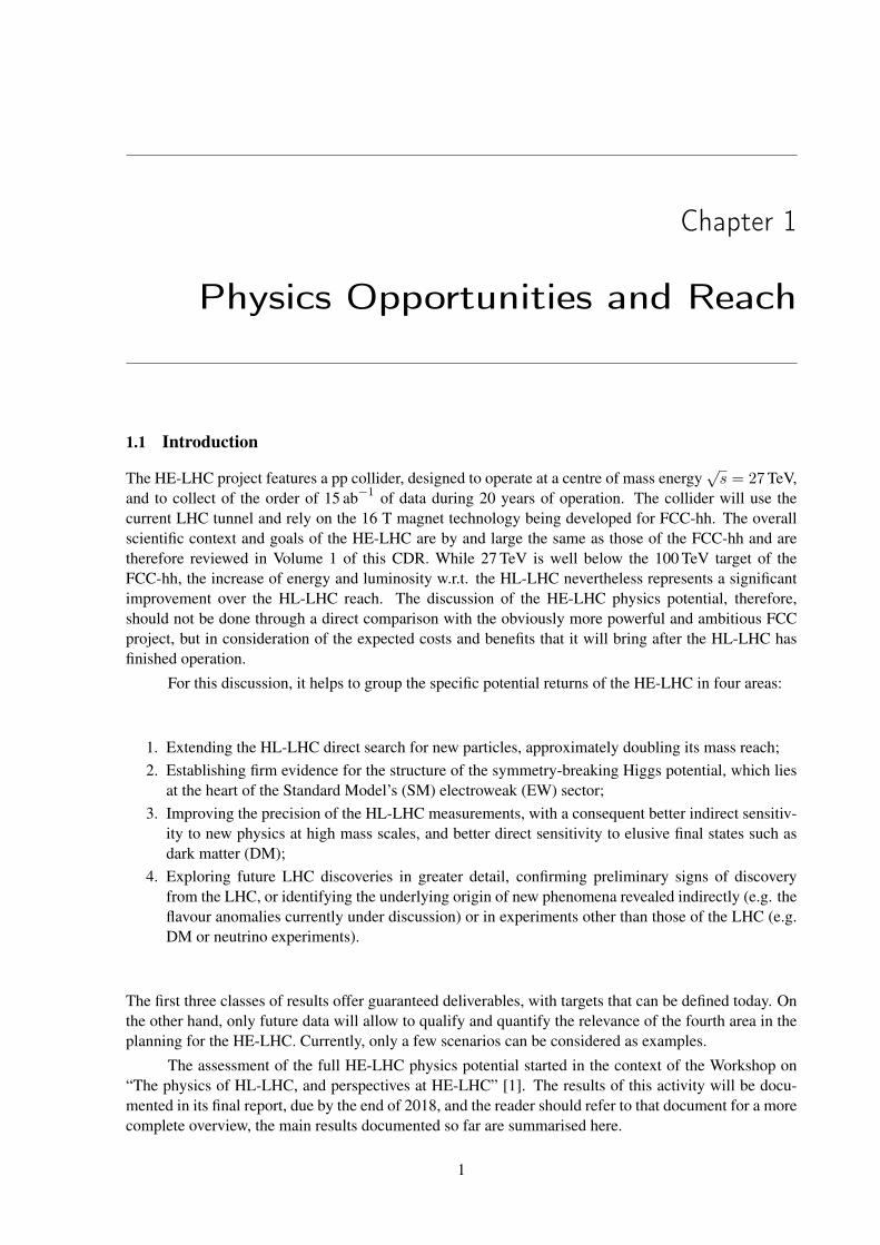
Figure 1.1: Estimate of the system mass (e.g. mZ′ or 2mg) that can be probed in searches for new
particles at HE-LHC, given an established reach at HL-LHC.
1.2 The Boundary Conditions for the HE-LHC Physics StudiesThe studies done by the FCC-hh detector working group, which led to the baseline detector design doc-umented in Volume 3, are relevant to the definition of an HE-LHC detector. In particular, most radiationissues will be comparable to FCC-hh, since the pp cross-sections and track densities at 27 and 100 TeVonly differ by∼20% and the pile-up conditions are assumed to be similar. In spite of this, it is prematureto propose a detector design specifically for HE-LHC. For FCC-hh, one can assume that the design andconstruction of the detectors will start from scratch, with complete freedom to explore optimum solu-tions in terms of technology, machine-detector interface and the corresponding civil engineering. In thecase of HE-LHC, one cannot avoid the tight constraints set by the existing cavern size, the infrastructureand the presence of the current detectors. The study of possible upgrade, refurbishing or replacementoptions for the ATLAS and CMS detectors, following the HL-LHC, is an extremely complex challenge,which would require the direct engagement of the experiments, and cannot be addressed at this time.As a result, ongoing HE-LHC physics studies make reference, at best, to an extrapolation of the ATLASand CMS HL-LHC detector configurations, modelled via Delphes [2] simulation parameters reproducingthe HL-LHC performance projections at 27 TeV and neglecting the impact of the much higher pile-upexpected at HE-LHC. In many cases, the physics studies are simply of a phenomenological nature, withbasic cuts and resolution/efficiency assumptions. The integrated luminosity benchmark will be set at15 ab−1, consistent with the accelerator projections.
1.3 The Discovery Reach Potential of HE-LHCThe HE-LHC is expected to extend the mass reach for the discovery of new particles by a factor of∼2 with respect to HL-LHC. While the study of individual scenarios must account in detail for thepossibly different evolution of signals and backgrounds with beam energy and include the new analysisopportunities offered by the larger statistics and kinematic reach available at 27 TeV, it is possible toprovide general estimates of the improved sensitivity by extrapolating the partonic luminosities that arerelevant for the production of various final states. This is shown in Fig. 1.1, obtained with the ColliderReach tool [3]. The thick green line includes the lines corresponding to the various possible initial states(qq, gg etc.), showing that the improvement in mass reach is rather independent of the specific type of
2P R E P R I N T
PHYSICS OPPORTUNITIES AND REACH
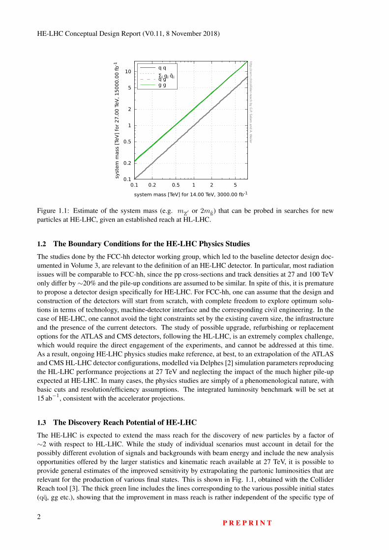
Figure 1.2: Discovery reach at the HE-LHC for gluinos and stops in various supersymmetric models,compared to the HL-LHC reach and to the expectations of several classes of natural supersymmetricmodels. The relevant areas lie under the horizontal lines (for the gluino) and to the left of the verticallines (for the stop).
particle(s) produced and only depends on the estimated reach at the HL-LHC. For example, new gaugebosons such as a Z′, whose reach at the HL-LHC is estimated to be in the range of 6 TeV, could beobserved by the HE-LHC up to a mass of ∼12 TeV. This qualitative conclusion is verified in the moredetailed studies done so far.
In several BSM scenarios, like for generic models of new Z′ gauge bosons, the extension of thereach by a factor of 2 relative to the LHC is just a small extra dent in a large range of possible masses.But there are interesting scenarios where the doubling of the reach can cover an important fraction of therelevant parameter space. A few concrete examples are given here and many more will be found in theWorkshop [1] report.
1.3.1 Supersymmetry
The first studies of the discovery reach for supersymmetry at HE-LHC have recently appeared [4,5]. Oneof the key questions is to what extent classes of “natural” supersymmetric models are within its reach andcan definitely be discovered or excluded. An example of the added value of a higher-energy option forthe LHC [4] is given in Fig. 1.2. The points in the plots correspond to parameter configurations of sev-eral supersymmetric models inspired by the requirement of a natural solution to the hierarchy problem,including constraints such as the proper Higgs mass. The models considered are described in [4], andinclude generalised mirage mediation (nGMM) and non-universal Higgs mass (NUHM) models. Whatclearly emerges from these plots is that, while HL-LHC can only cover part of the parameter space of theillustrated models, HE-LHC covers it entirely. With the exception of the models labeled by red (green)dots, where the gluino (stop) mass is typically larger than the HE-LHC reach, all other models wouldallow the 5σ discovery via the observation of both gluino and stop.
1.3.2 WIMP searches
Reference [6] presented a study of the search for weakly-interacting massive particles (WIMPs) as darkmatter (DM) candidates. The study follows the pattern of similar ones discussed in Volume 1 at 100 TeV,
P R E P R I N T3
HE-LHC Conceptual Design Report (V0.11, 8 November 2018)
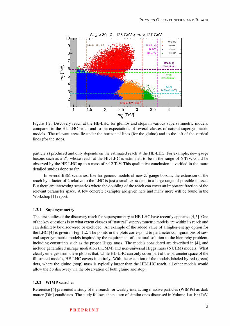
Figure 1.3: The reach of HE-LHC in the search for a wino (left) or higgsino (right) DM WIMP candidate,using a disappearing charged track signature [6]. The bands limited by the solid and dashed lines showthe range obtained by modifying the central value of the background estimate by a factor of five. Theresults are compared to the reach of HL-LHC and FCC-hh.
and also includes a comparison with the 100 TeV (and HL-LHC) results. From their conclusions, adisappearing charged track analysis at the HE-LHC can probe Higgsino-like (wino-like) DM mass of upto 600 GeV (2.1 TeV) at the 95% confidence limit (C.L.). These results, shown in Fig. 1.3, improve onthe expected reach of HL-LHC, namely 300 GeV (900 GeV). While these results at the HE-LHC comeshort of saturating the full range of masses for possible DM WIMPs (a goal that requires the power of thefull FCC-hh, as shown by Fig. 1.3 and as discussed in Volume 1), the mass range accessible to HE-LHCgreatly extends the HL-LHC potential and can be complementary to the indirect detection probes usinggamma rays from dwarf-spheroidal galaxies [6].
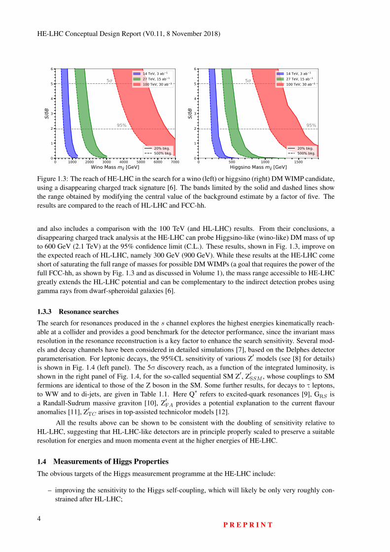
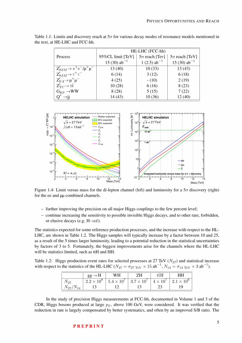
1.3.3 Resonance searchesThe search for resonances produced in the s channel explores the highest energies kinematically reach-able at a collider and provides a good benchmark for the detector performance, since the invariant massresolution in the resonance reconstruction is a key factor to enhance the search sensitivity. Several mod-els and decay channels have been considered in detailed simulations [7], based on the Delphes detectorparameterisation. For leptonic decays, the 95%CL sensitivity of various Z′ models (see [8] for details)is shown in Fig. 1.4 (left panel). The 5σ discovery reach, as a function of the integrated luminosity, isshown in the right panel of Fig. 1.4, for the so-called sequential SM Z′, Z′SSM , whose couplings to SMfermions are identical to those of the Z boson in the SM. Some further results, for decays to τ leptons,to WW and to di-jets, are given in Table 1.1. Here Q∗ refers to excited-quark resonances [9], GRS isa Randall-Sudrum massive graviton [10], Z′FA provides a potential explanation to the current flavouranomalies [11], Z′TC arises in top-assisted technicolor models [12].
All the results above can be shown to be consistent with the doubling of sensitivity relative toHL-LHC, suggesting that HL-LHC-like detectors are in principle properly scaled to preserve a suitableresolution for energies and muon momenta event at the higher energies of HE-LHC.
1.4 Measurements of Higgs PropertiesThe obvious targets of the Higgs measurement programme at the HE-LHC include:
– improving the sensitivity to the Higgs self-coupling, which will likely be only very roughly con-strained after HL-LHC;
4P R E P R I N T
PHYSICS OPPORTUNITIES AND REACH
Table 1.1: Limits and discovery reach at 5σ for various decay modes of resonance models mentioned inthe text, at HE-LHC and FCC-hh.
HE-LHC (FCC-hh)Process 95%CL limit [TeV] 5σ reach [Tev] 5σ reach [TeV]
15 (30) ab−1 1 (2.5) ab−1 15 (30) ab−1
Z′SSM→ e+e−/µ+µ− 13 (40) 10 (33) 13 (43)Z′SSM→ τ
+τ− 6 (14) 3 (12) 6 (18)
Z′FA→ µ+µ− 4 (25) - (10) 2 (19)Z′TC→ tt 10 (28) 6 (16) 8 (23)GRS →WW 8 (28) 5 (15) 7 (22)Q∗ →jj 14 (43) 10 (36) 12 (40)
Mass [TeV]2 4 6 8 10 12 14
Z’)*B
R [pb]
→(p
p
σ
6−
10
5−
10
4−10
3−
10
2−10
1−10
1Median expected.
95% expected
68% expected
Z′SSM
Z′χ
Z′ψ
Z′I
Z′η
Z′LRM
HELHC simulation
√s = 27TeV∫ Ldt = 15ab −1
ll(l = e, μ)
Mass [TeV]
2 4 6 8 10 12 14
]-1
Int. L
um
inosi
ty [fb
1−10
1
10
210
310
410
510
610
ee
µµ
ll
HELHC simulation
√s = 27TeV
discoveryσIntegrated luminosity versus mass for a 5
SSMZ’
-115 ab
-11 ab
Figure 1.4: Limit versus mass for the di-lepton channel (left) and luminosity for a 5σ discovery (right)for the ee and µµ combined channels.
– further improving the precision on all major Higgs couplings to the few percent level;– continue increasing the sensitivity to possible invisible Higgs decays, and to other rare, forbidden,
or elusive decays (e.g. H→cc).
The statistics expected for some reference production processes, and the increase with respect to the HL-LHC, are shown in Table 1.2. The Higgs samples will typically increase by a factor between 10 and 25,as a result of the 5 times larger luminosity, leading to a potential reduction in the statistical uncertaintiesby factors of 3 to 5. Fortunately, the biggest improvements arise for the channels where the HL-LHCwill be statistics limited, such as ttH and HH.
Table 1.2: Higgs production event rates for selected processes at 27 TeV (N27) and statistical increasewith respect to the statistics of the HL-LHC (N27 = σ27 TeV × 15 ab−1, N14 = σ14 TeV × 3 ab−1).
gg→H WH ZH ttH HHN27 2.2× 10⁸ 5.4× 10⁷ 3.7× 10⁷ 4× 10⁷ 2.1× 10⁶
N27/N14 13 12 13 23 19
In the study of precision Higgs measurements at FCC-hh, documented in Volume 1 and 3 of theCDR, Higgs bosons produced at large pT , above 100 GeV, were considered. It was verified that thereduction in rate is largely compensated by better systematics, and often by an improved S/B ratio. The
P R E P R I N T5
HE-LHC Conceptual Design Report (V0.11, 8 November 2018)
[GeV]HT,min
p50 100 150 200 250 300 350 400 450 500
(%
)µ
/ µ δ
1
10
stat. + syst. + lumi
stat. + syst.
stat. only
stat. + syst. + lumi
stat. + syst.
stat. only
HE-LHC Simulation (Delphes)
= 27 TeVs
-1 L = 15 ab
γγ → H
[GeV]HT,min
p50 100 150 200 250 300 350 400 450 500
(%
)µ
/ µ δ
1
10
stat. + syst. + lumi
stat. + syst.
stat. only
stat. + syst. + lumi
stat. + syst.
stat. only
HE-LHC Simulation (Delphes)
= 27 TeVs
-1 L = 15 ab
4l→ H µ l=e/
[GeV]HT,min
p50 100 150 200 250 300 350 400 450 500
(%
)µ
/ µ δ
1
10
210
stat. + syst. + lumi
stat. + syst.
stat. only
stat. + syst. + lumi
stat. + syst.
stat. only
HE-LHC Simulation (Delphes)
= 27 TeVs
-1 L = 15 ab
µµ → H
[GeV]HT,min
p50 100 150 200 250 300 350 400 450 500
(%
)µ
/ µ δ
10
210
stat. + syst. + lumi
stat. + syst.
stat. only
stat. + syst. + lumi
stat. + syst.
stat. only
HE-LHC Simulation (Delphes)
= 27 TeVs
-1 L = 15 ab
γ ll→ H µ l=e/
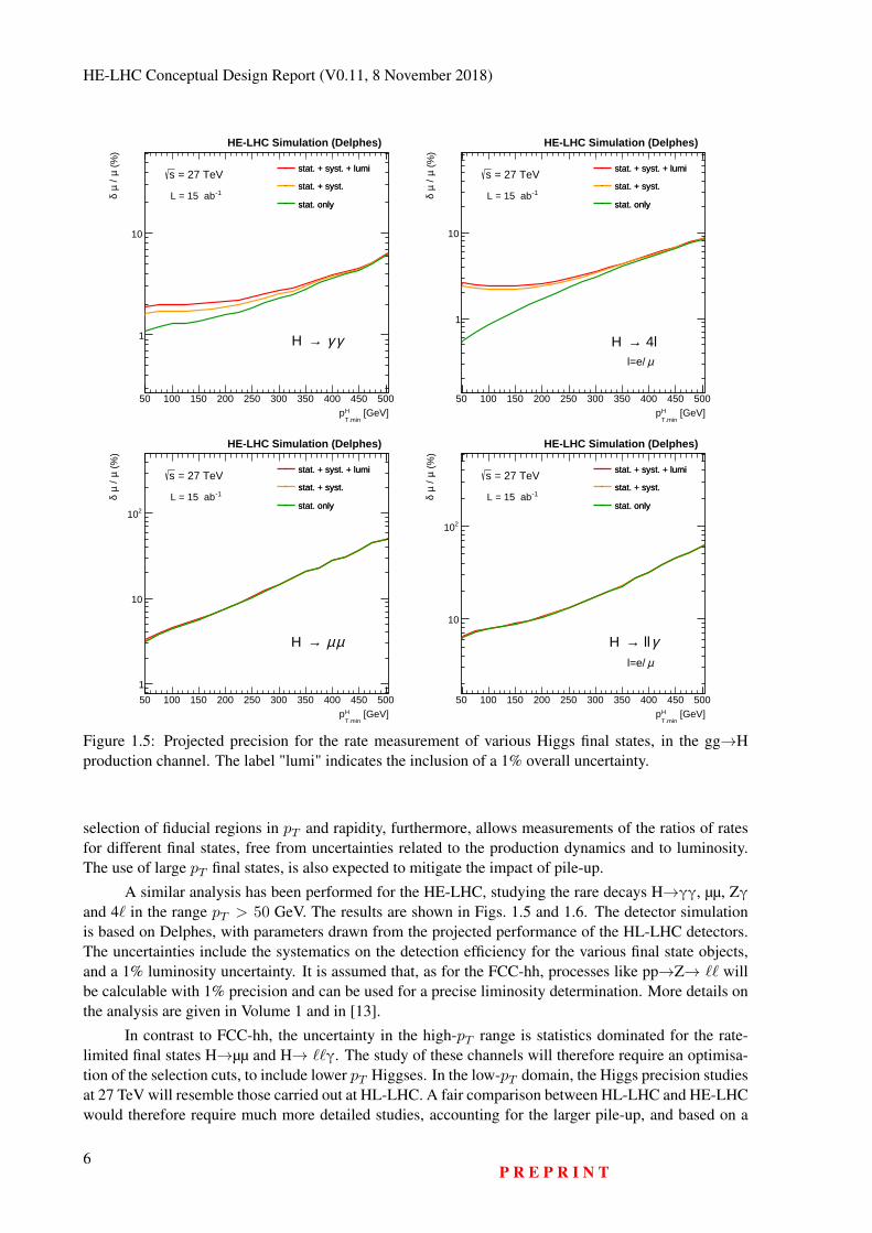
Figure 1.5: Projected precision for the rate measurement of various Higgs final states, in the gg→Hproduction channel. The label "lumi" indicates the inclusion of a 1% overall uncertainty.
selection of fiducial regions in pT and rapidity, furthermore, allows measurements of the ratios of ratesfor different final states, free from uncertainties related to the production dynamics and to luminosity.The use of large pT final states, is also expected to mitigate the impact of pile-up.
A similar analysis has been performed for the HE-LHC, studying the rare decays H→γγ, µµ, Zγand 4` in the range pT > 50 GeV. The results are shown in Figs. 1.5 and 1.6. The detector simulationis based on Delphes, with parameters drawn from the projected performance of the HL-LHC detectors.The uncertainties include the systematics on the detection efficiency for the various final state objects,and a 1% luminosity uncertainty. It is assumed that, as for the FCC-hh, processes like pp→Z→ `` willbe calculable with 1% precision and can be used for a precise liminosity determination. More details onthe analysis are given in Volume 1 and in [13].
In contrast to FCC-hh, the uncertainty in the high-pT range is statistics dominated for the rate-limited final states H→µµ and H→ ``γ. The study of these channels will therefore require an optimisa-tion of the selection cuts, to include lower pT Higgses. In the low-pT domain, the Higgs precision studiesat 27 TeV will resemble those carried out at HL-LHC. A fair comparison between HL-LHC and HE-LHCwould therefore require much more detailed studies, accounting for the larger pile-up, and based on a
6P R E P R I N T
PHYSICS OPPORTUNITIES AND REACH
[GeV]HT,min
p50 100 150 200 250 300 350 400 450 500
) )
(%)
µµ e
e→
) / B
R(H
γγ
→ (
BR
(H
δ
1
10
210 stat + syst (cons.)
stat + syst (optim.)
stat. only
stat + syst (cons.)
stat + syst (optim.)
stat. only
HE-LHC Simulation (Delphes)
= 27 TeVs
-1 L = 15 ab
)µµ ee→BR(H )γγ →BR(H
[GeV]HT,min
p50 100 150 200 250 300 350 400 450 500
) )
(%)
µµ →
) / B
R(H
γγ
→ (
BR
(H
δ
1
10
210
stat + syst (cons.)
stat + syst (optim.)
stat. only
stat + syst (cons.)
stat + syst (optim.)
stat. only
HE-LHC Simulation (Delphes)
= 27 TeVs
-1 L = 15 ab
)µµ →BR(H )γγ →BR(H
[GeV]HT,min
p50 100 150 200 250 300 350 400 450 500
) )
(%)
µµµµ →
) / B
R(H
µµ
→ (
BR
(H
δ
1
10
210
stat + syst (cons.)
stat + syst (optim.)
stat. only
stat + syst (cons.)
stat + syst (optim.)
stat. only
HE-LHC Simulation (Delphes)
= 27 TeVs
-1 L = 15 ab
)µµµµ →BR(H )µµ →BR(H
[GeV]HT,min
p50 100 150 200 250 300 350 400 450 500
) )
(%)
µµµµ →
) / B
R(H
γµµ
→ (
BR
(H
δ
1
10
210
stat + syst (cons.)
stat + syst (optim.)
stat. only
stat + syst (cons.)
stat + syst (optim.)
stat. only
HE-LHC Simulation (Delphes)
= 27 TeVs
-1 L = 15 ab
)µµµµ →BR(H )γµµ →BR(H
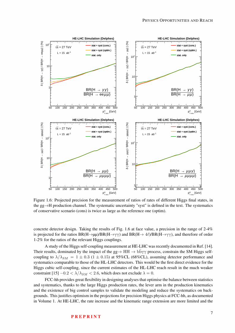
Figure 1.6: Projected precision for the measurement of ratios of rates of different Higgs final states, inthe gg→H production channel. The systematic uncertainty "syst" is defined in the text. The systematicsof conservative scenario (cons) is twice as large as the reference one (optim).
concrete detector design. Taking the results of Fig. 1.6 at face value, a precision in the range of 2-4%is projected for the ratios BR(H→µµ)/BR(H→γγ) and BR(H→ 4`)/BR(H→γγ), and therefore of order1-2% for the ratios of the relevant Higgs couplings.
A study of the Higgs self-coupling measurement at HE-LHC was recently documented in Ref. [14].Their results, dominated by the impact of the gg→ HH → bbγγ process, constrain the SM Higgs self-coupling to λ/λSM = 1 ± 0.3 (1 ± 0.15) at 95%CL (68%CL), assuming detector performance andsystematics comparable to those of the HL-LHC detectors. This would be the first direct evidence for theHiggs cubic self-coupling, since the current estimates of the HL-LHC reach result in the much weakerconstraint [15] −0.2 < λ/λSM < 2.6, which does not exclude λ = 0.
FCC-hh provides great flexibility in designing analyses that optimise the balance between statisticsand systematics, thanks to the large Higgs production rates, the lever arm in the production kinematicsand the existence of big control samples to validate the modeling and reduce the systematics on back-grounds. This justifies optimism in the projections for precision Higgs physics at FCC-hh, as documentedin Volume 1. At HE-LHC, the rate increase and the kinematic range extension are more limited and the
P R E P R I N T7
HE-LHC Conceptual Design Report (V0.11, 8 November 2018)
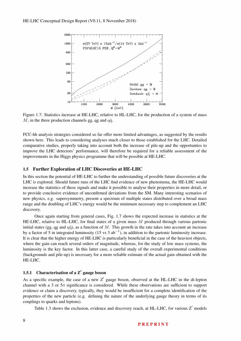
Figure 1.7: Statistics increase at HE-LHC, relative to HL-LHC, for the production of a system of massM , in the three production channels gg, qg and qq.
FCC-hh analysis strategies considered so far offer more limited advantages, as suggested by the resultsshown here. This leads to considering analyses much closer to those established for the LHC. Detailedcomparative studies, properly taking into account both the increase of pile-up and the opportunties toimprove the LHC detectors’ performance, will therefore be required for a reliable assessment of theimprovements in the Higgs physics programme that will be possible at HE-LHC.
1.5 Further Exploration of LHC Discoveries at HE-LHCIn this section the potential of HE-LHC to further the understanding of possible future discoveries at theLHC is explored. Should future runs of the LHC find evidence of new phenomena, the HE-LHC wouldincrease the statistics of these signals and make it possible to analyse their properties in more detail, orto provide conclusive evidence of unconfirmed deviations from the SM. Many interesting scenarios ofnew physics, e.g. supersymmetry, present a spectrum of multiple states distributed over a broad massrange and the doubling of LHC’s energy would be the minimum necessary step to complement an LHCdiscovery.
Once again starting from general cases, Fig. 1.7 shows the expected increase in statistics at theHE-LHC, relative to HL-LHC, for final states of a given mass M produced through various partonicinitial states (gg, qg and qq), as a function of M . This growth in the rate takes into account an increaseby a factor of 5 in integrated luminosity (15 vs 3 ab−1), in addition to the partonic luminosity increase.It is clear that the higher energy of HE-LHC is particularly beneficial in the case of the heaviest objects,where the gain can reach several orders of magnitude, whereas, for the study of low mass systems, theluminosity is the key factor. In this latter case, a careful study of the overall experimental conditions(backgrounds and pile-up) is necessary for a more reliable estimate of the actual gain obtained with theHE-LHC.
1.5.1 Characterisation of a Z′ gauge bosonAs a specific example, the case of a new Z′ gauge boson, observed at the HL-LHC in the di-leptonchannel with a 3 or 5σ significance is considered. While these observations are sufficient to supportevidence or claim a discovery, typically, they would be insufficient for a complete identification of theproperties of the new particle (e.g. defining the nature of the underlying gauge theory in terms of itscouplings to quarks and leptons).
Table 1.3 shows the exclusion, evidence and discovery reach, at HL-LHC, for various Z′ models
8P R E P R I N T
PHYSICS OPPORTUNITIES AND REACH
Table 1.3: Mass reach at HL-LHC (in TeV) for various Z′ models discussed in [8, 16].
Model 95%CM 3σ 5σSSM 6.6 6.1 5.6LRM 6.4 5.9 5.4ψ 6.1 5.6 5.1χ 6.2 5.7 5.3η 6.2 5.6 5.2I 6.0 5.5 5.1
FBA0.4− 0.3− 0.2− 0.1− 0 0.1
yr
1.8
1.9
2
2.1
2.2
2.3HE-LHC simulation
=6TeVZ’m -1L = 15 ab
(6TeV)=200GeVll M∆
SSM η χ
LRM ψ I
Cross section [fb]0 1 2 3 4 5 6 7 8
ψ
I
χ
LRM
SSM
ηqq bb tt
FCC simulation
=6TeVZ’
m ∫ Ldt = 15ab −1
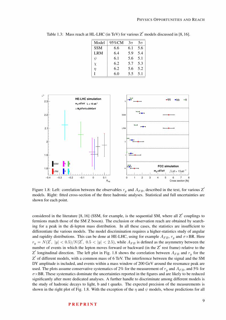
Figure 1.8: Left: correlation between the observables ry and AFB , described in the text, for various Z′
models. Right: fitted cross-section of the three hadronic analyses. Statistical and full uncertainties areshown for each point.
considered in the literature [8, 16] (SSM, for example, is the sequential SM, where all Z′ couplings tofermions match those of the SM Z boson). The exclusion or observation reach are obtained by search-ing for a peak in the di-lepton mass distribution. In all these cases, the statistics are insufficient todifferentiate the various models. The model discrimination requires a higher-statistics study of angularand rapidity distributions. This can be done at HE-LHC, using for example AFB , ry and σ×BR. Herery = N(Z′, |y| < 0.5)/N(Z′, 0.5 < |y| < 2.5), while AFB is defined as the asymmetry between thenumber of events in which the lepton moves forward or backward (in the Z′ rest frame) relative to theZ′ longitudinal direction. The left plot in Fig. 1.8 shows the correlation between AFB and ry for theZ′ of different models, with a common mass of 6 TeV. The interference between the signal and the SMDY amplitude is included, and events within a mass window of 200 GeV around the resonance peak areused. The plots assume conservative systematics of 2% for the measurement of ry and AFB , and 5% forσ×BR. These systematics dominate the uncertainties reported in the figures and are likely to be reducedsignificantly after more dedicated analyses. A further handle to discriminate among different models isthe study of hadronic decays to light, b and t quarks. The expected precision of the measurements isshown in the right plot of Fig. 1.8. With the exception of the η and ψ models, whose predictions for all
P R E P R I N T9
HE-LHC Conceptual Design Report (V0.11, 8 November 2018)
variables considered are rather degenerate, all other models can be separated through a combination ofdifferent observations. For example, the SSM and ψ models, which have very close predictions for ryand AFB , have measurably different fractions of b or t final states.
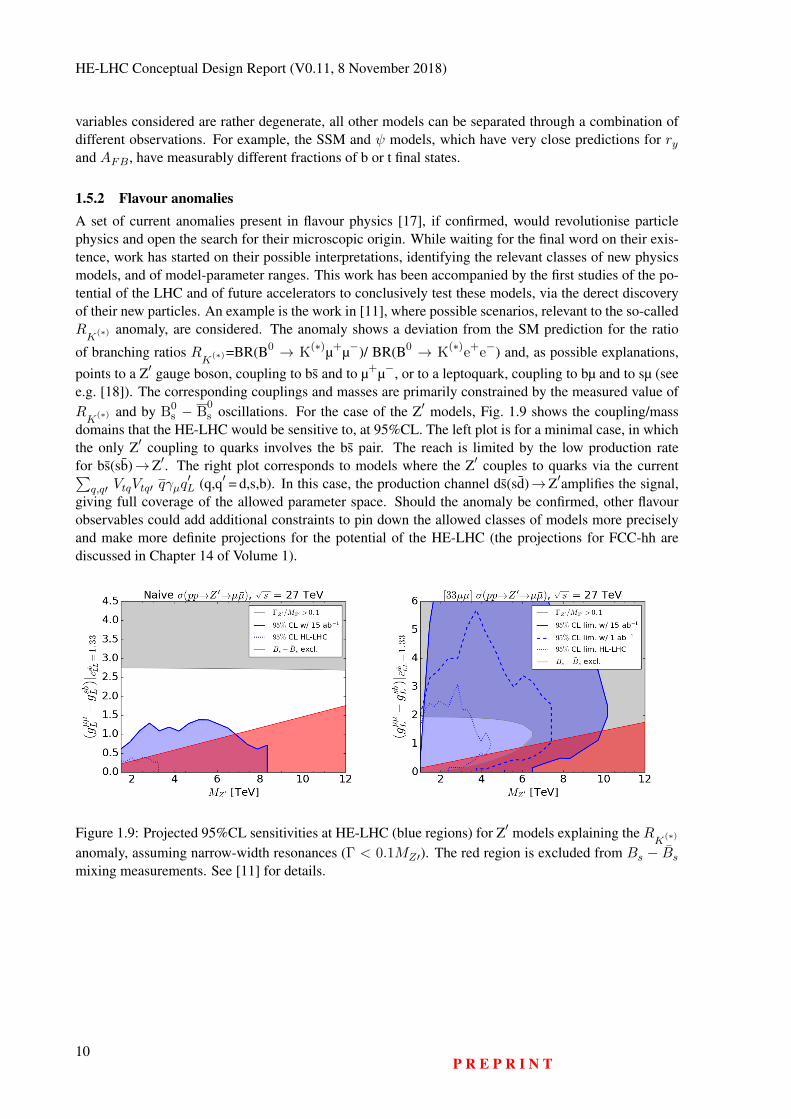
1.5.2 Flavour anomaliesA set of current anomalies present in flavour physics [17], if confirmed, would revolutionise particlephysics and open the search for their microscopic origin. While waiting for the final word on their exis-tence, work has started on their possible interpretations, identifying the relevant classes of new physicsmodels, and of model-parameter ranges. This work has been accompanied by the first studies of the po-tential of the LHC and of future accelerators to conclusively test these models, via the derect discoveryof their new particles. An example is the work in [11], where possible scenarios, relevant to the so-calledRK
(∗) anomaly, are considered. The anomaly shows a deviation from the SM prediction for the ratio
of branching ratios RK
(∗)=BR(B0 → K(∗)µ+µ−)/ BR(B0 → K(∗)e+e−) and, as possible explanations,points to a Z′ gauge boson, coupling to bs and to µ+µ−, or to a leptoquark, coupling to bµ and to sµ (seee.g. [18]). The corresponding couplings and masses are primarily constrained by the measured value ofRK
(∗) and by B0s − B
0s oscillations. For the case of the Z′ models, Fig. 1.9 shows the coupling/mass
domains that the HE-LHC would be sensitive to, at 95%CL. The left plot is for a minimal case, in whichthe only Z′ coupling to quarks involves the bs pair. The reach is limited by the low production ratefor bs(sb)→Z′. The right plot corresponds to models where the Z′ couples to quarks via the current∑
q,q′ VtqVtq′ qγµq′L (q,q′ = d,s,b). In this case, the production channel ds(sd)→Z′amplifies the signal,
giving full coverage of the allowed parameter space. Should the anomaly be confirmed, other flavourobservables could add additional constraints to pin down the allowed classes of models more preciselyand make more definite projections for the potential of the HE-LHC (the projections for FCC-hh arediscussed in Chapter 14 of Volume 1).
Figure 1.9: Projected 95%CL sensitivities at HE-LHC (blue regions) for Z′ models explaining the RK
(∗)
anomaly, assuming narrow-width resonances (Γ < 0.1MZ′). The red region is excluded from Bs − Bsmixing measurements. See [11] for details.
10P R E P R I N T
Chapter 2
Collider Design and Performance
2.1 Requirements and Design Considerations
The HE-LHC should provide proton-proton collisions at about twice the collision energy of the LHC,using the existing LHC tunnel infrastructure, without any increase of the tunnel cross section. Reachinga target beam energy of 13.5 TeV relies on the FCC-hh magnet technology. The existing LHC dipolemagnets which have a nominal field of 8.33 Tesla will be replaced by FCC-type 16 Tesla dipole magnets.Achieving a centre-of-mass energy close to 27 TeV with 16 T magnets requires a dipole filling factorsimilar to that of the LHC. Following a preliminary design optimisation of compact high-field dipolemagnets, the inter-beam distance for the HE-LHC is set to be 250 mm, significantly larger than the194 mm of the existing LHC. The lengths of the magnet interconnects are chosen in the same way as theinterbeam distance – equal to those of the FCC-hh. However, the HE-LHC dipole magnets are curved,those of FCC-hh straight.
An integrated luminosity exceeding 10 ab−1 is within reach over about 20 years of operation of theHE-LHC. After the LHC Injector Upgrade (LIU) [19], scheduled for 2020, an extremely bright protonbeam will be available for injection into the HE-LHC. The luminosity evolution during HE-LHC physicsis determined by the combined effects of proton burn off and significant radiation damping.
In the HE-LHC, both the synchrotron radiation power and in particular, the photon flux are muchhigher than in the LHC. The FCC-hh beamscreen design offers an adequate solution for the challeng-ing cryogenic beam-vacuum system. In addition, the HL-LHC R&D effort [20] provides several novelelements essential for the HE-LHC, such as crab cavities and low-impedance collimators, as well aspossible add-ons such as electron lenses, long-range beam-beam compensation and new optics solutions.
Combining advanced technological systems and beam-dynamics solutions developed for the LHC,HL-LHC, FCC-hh and the LIU, facilitates the formulation of a robust accelerator design for the HE-LHCwith an excellent performance forecast.
Section 2.2 presents key parameters of the HE-LHC and the following Section 2.3 examines theprimary challenges. Optics design, collimation, longitudinal parameters, and beam dynamics issues arepresented in Section 2.4. In Section 2.5 the proton-proton physics operation and luminosity performanceare reviewed.
In addition to delivering proton-proton physics at the energy frontier, the HE-LHC could oper-ate as the world’s highest-energy heavy-ion and ion-proton collider. The corresponding performanceparameters are discussed in Section 2.6. By adding a 60 GeV electron beam from a multi-pass energy-recovery linac, as proposed for the LHeC, the HE-LHC could also provide high-energy lepton-protonand lepton-ion collisions. This “HE-LHeC” option is reviewed in Section 2.7.
11
HE-LHC Conceptual Design Report (V0.11, 8 November 2018)
2.2 Parameter ChoicesThe HE-LHC design assumes essentially the same beam parameters as the HL-LHC. Beams compatiblewith the HL-LHC requirements will be available from the upgraded LHC injector complex. Adoptingthe beam parameters of the HL-LHC, the HE-LHC bunch population is taken to be 2.2 × 10¹¹ and thenormalised transverse rms emittance at the start of a store to be 2.5 µm. The bunch spacing of 25 ns ischosen to be the same as in the LHC and HL-LHC.
The baseline design parameters are summarised in Table 2.1, which also presents a comparisonwith the corresponding values for LHC, HL-LHC and FCC-hh [21]. It is assumed that the HE-LHC willaccommodate two high-luminosity interaction-points (IPs) 1 and 5, at the locations of the present ATLASand CMS experiments. IPs 2 and 8 could host secondary experiments, e.g. with a lepton-hadron collisionpoint, combined with injection, as for the present LHC, or the space available could be exploited to serveother needs, e.g. for an extended high energy injection section or for collimation.
At present, optics solutions with a short-term (105 turns) dynamic aperture exceeding 10σ onlyexist for an injection energy above 1 TeV. An injection energy of 1.3 TeV, as could be provided by asuperconducting SPS (scSPS), is the current baseline. The creation of artificial pinning centres (APCs)in the Nb3Sn superconductor might potentially enable an injection energy of 900 GeV or below. Thepossibility of 450 GeV injection requires further studies.
2.3 Design Challenges and ApproachesKey design challenges include: (1) the handling of high levels of synchrotron radiation inside the coldarcs; (2) the choice of injection energy in view of significantly decreased physical aperture, greatlyenhanced field errors for Nb3Sn magnets at low energy and a possibly larger energy swing; (3) the eventpile-up in the experiment detectors; (4) achieving the required high dipole packing density in the arcs;(5) developing optics for the experiment insertions, beam extraction and for collimation, all of whichmust fit into the existing straight sections, without the possibility of applying any of the length scalingused for the FCC-hh. The optics design challenges for the arc and IRs, beam extraction and collimationwill be addressed in Section 2.4.
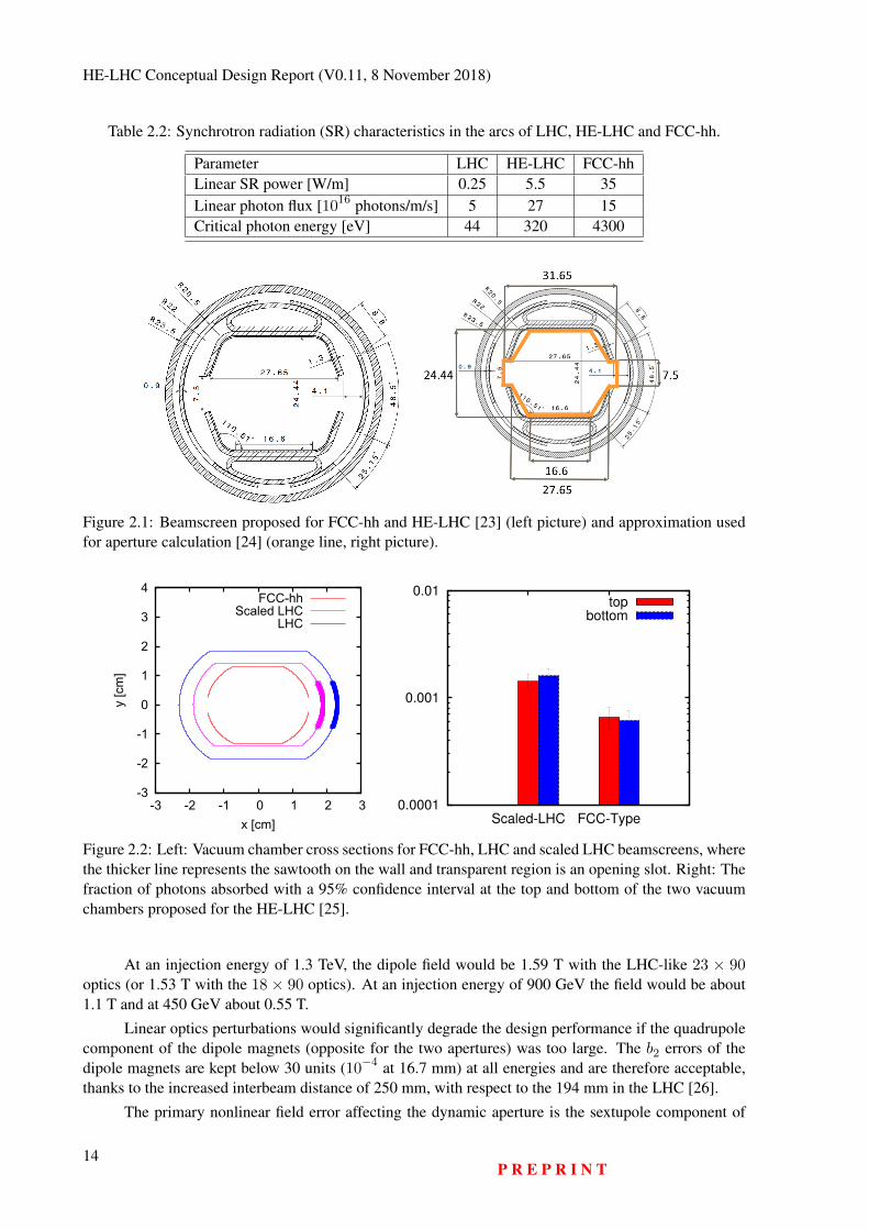
2.3.1 Synchrotron RadiationThe synchrotron radiation power and photon flux are both much higher than those of the LHC and,remarkably, the flux is even higher than for the FCC-hh (see Table 2.2).
The FCC-hh beamscreen [22], illustrated in Fig. 2.1, offers an optimum solution for the HE-LHCcryo-beam vacuum system. Compared with an LHC-type, this beamscreen developed for the FCC-hh features greatly enlarged cooling capillaries for increased helium mass flow, a large surface-area ofshielded pumping slots for reduced impedance and high pumping speed and a kind of “folded antecham-ber” to minimise the number of photoelectrons generated in the beam pipe itself.
The FCC-hh and HE-LHC beamscreens operate at an elevated temperature of 50 K instead of theLHC’s 5–20 K because the higher temperature improves the Carnot efficiency. The large pumping speedis appropriate for the high out-gassing rates caused by the extremely high photon flux from synchrotronradiation. In addition, the FCC-hh type beamscreen reduces the fraction of photons reflected towards thetop and bottom of the vacuum chamber by a factor 2–3 compared to an LHC-type beamscreen [25], as isillustrated in Fig. 2.2. This helps suppress the initiation of electron-cloud build up due to photoelectrons.
2.3.2 Dynamic and Physical Aperture at InjectionInjection into the HE-LHC could be accomplished from a new fast ramping superconducting (SC) syn-chrotron in the SPS tunnel (scSPS). SC magnets with double-layer coils would allow an injection energyof 1.3 TeV, which provides an adequate dynamic and physical aperture at injection and has been chosenas a solid baseline. Alternative injector scenarios include injection at 900 GeV from a single-layer coil12
P R E P R I N T
COLLIDER DESIGN AND PERFORMANCE
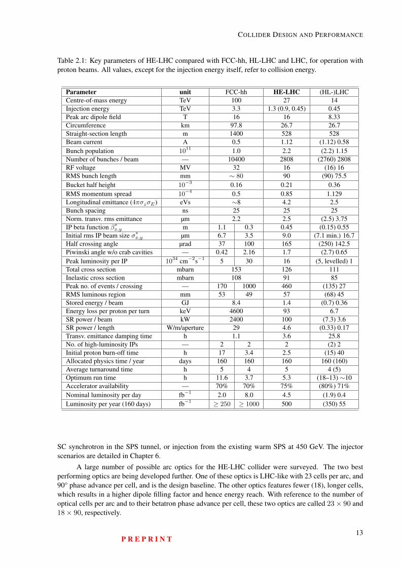
Table 2.1: Key parameters of HE-LHC compared with FCC-hh, HL-LHC and LHC, for operation withproton beams. All values, except for the injection energy itself, refer to collision energy.
Parameter unit FCC-hh HE-LHC (HL-)LHCCentre-of-mass energy TeV 100 27 14Injection energy TeV 3.3 1.3 (0.9, 0.45) 0.45Peak arc dipole field T 16 16 8.33Circumference km 97.8 26.7 26.7Straight-section length m 1400 528 528Beam current A 0.5 1.12 (1.12) 0.58Bunch population 1011 1.0 2.2 (2.2) 1.15Number of bunches / beam — 10400 2808 (2760) 2808RF voltage MV 32 16 (16) 16RMS bunch length mm ∼ 80 90 (90) 75.5Bucket half height 10−3 0.16 0.21 0.36RMS momentum spread 10−4 0.5 0.85 1.129Longitudinal emittance (4πσzσE) eVs ∼8 4.2 2.5Bunch spacing ns 25 25 25Norm. transv. rms emittance µm 2.2 2.5 (2.5) 3.75IP beta function β∗
x,y m 1.1 0.3 0.45 (0.15) 0.55Initial rms IP beam size σ∗
x,y µm 6.7 3.5 9.0 (7.1 min.) 16.7Half crossing angle µrad 37 100 165 (250) 142.5Piwinski angle w/o crab cavities — 0.42 2.16 1.7 (2.7) 0.65Peak luminosity per IP 1034 cm−2s−1 5 30 16 (5, levelled) 1Total cross section mbarn 153 126 111Inelastic cross section mbarn 108 91 85Peak no. of events / crossing — 170 1000 460 (135) 27RMS luminous region mm 53 49 57 (68) 45Stored energy / beam GJ 8.4 1.4 (0.7) 0.36Energy loss per proton per turn keV 4600 93 6.7SR power / beam kW 2400 100 (7.3) 3.6SR power / length W/m/aperture 29 4.6 (0.33) 0.17Transv. emittance damping time h 1.1 3.6 25.8No. of high-luminosity IPs — 2 2 2 (2) 2Initial proton burn-off time h 17 3.4 2.5 (15) 40Allocated physics time / year days 160 160 160 160 (160)Average turnaround time h 5 4 5 4 (5)Optimum run time h 11.6 3.7 5.3 (18–13) ∼10Accelerator availability — 70% 70% 75% (80%) 71%Nominal luminosity per day fb−1 2.0 8.0 4.5 (1.9) 0.4Luminosity per year (160 days) fb−1 ≥ 250 ≥ 1000 500 (350) 55
SC synchrotron in the SPS tunnel, or injection from the existing warm SPS at 450 GeV. The injectorscenarios are detailed in Chapter 6.
A large number of possible arc optics for the HE-LHC collider were surveyed. The two bestperforming optics are being developed further. One of these optics is LHC-like with 23 cells per arc, and90° phase advance per cell, and is the design baseline. The other optics features fewer (18), longer cells,which results in a higher dipole filling factor and hence energy reach. With reference to the number ofoptical cells per arc and to their betatron phase advance per cell, these two optics are called 23× 90 and18× 90, respectively.
P R E P R I N T13
HE-LHC Conceptual Design Report (V0.11, 8 November 2018)
Table 2.2: Synchrotron radiation (SR) characteristics in the arcs of LHC, HE-LHC and FCC-hh.
Parameter LHC HE-LHC FCC-hhLinear SR power [W/m] 0.25 5.5 35Linear photon flux [1016 photons/m/s] 5 27 15Critical photon energy [eV] 44 320 4300
Figure 2.1: Beamscreen proposed for FCC-hh and HE-LHC [23] (left picture) and approximation usedfor aperture calculation [24] (orange line, right picture).
-3
-2
-1
0
1
2
3
4
-3 -2 -1 0 1 2 3
y [cm
]
x [cm]
FCC-hhScaled LHC
LHC
0.0001
0.001
0.01
Scaled-LHC FCC-Type
topbottom
Figure 2.2: Left: Vacuum chamber cross sections for FCC-hh, LHC and scaled LHC beamscreens, wherethe thicker line represents the sawtooth on the wall and transparent region is an opening slot. Right: Thefraction of photons absorbed with a 95% confidence interval at the top and bottom of the two vacuumchambers proposed for the HE-LHC [25].
At an injection energy of 1.3 TeV, the dipole field would be 1.59 T with the LHC-like 23 × 90optics (or 1.53 T with the 18 × 90 optics). At an injection energy of 900 GeV the field would be about1.1 T and at 450 GeV about 0.55 T.
Linear optics perturbations would significantly degrade the design performance if the quadrupolecomponent of the dipole magnets (opposite for the two apertures) was too large. The b2 errors of thedipole magnets are kept below 30 units (10−4 at 16.7 mm) at all energies and are therefore acceptable,thanks to the increased interbeam distance of 250 mm, with respect to the 194 mm in the LHC [26].
The primary nonlinear field error affecting the dynamic aperture is the sextupole component of
14P R E P R I N T
COLLIDER DESIGN AND PERFORMANCE
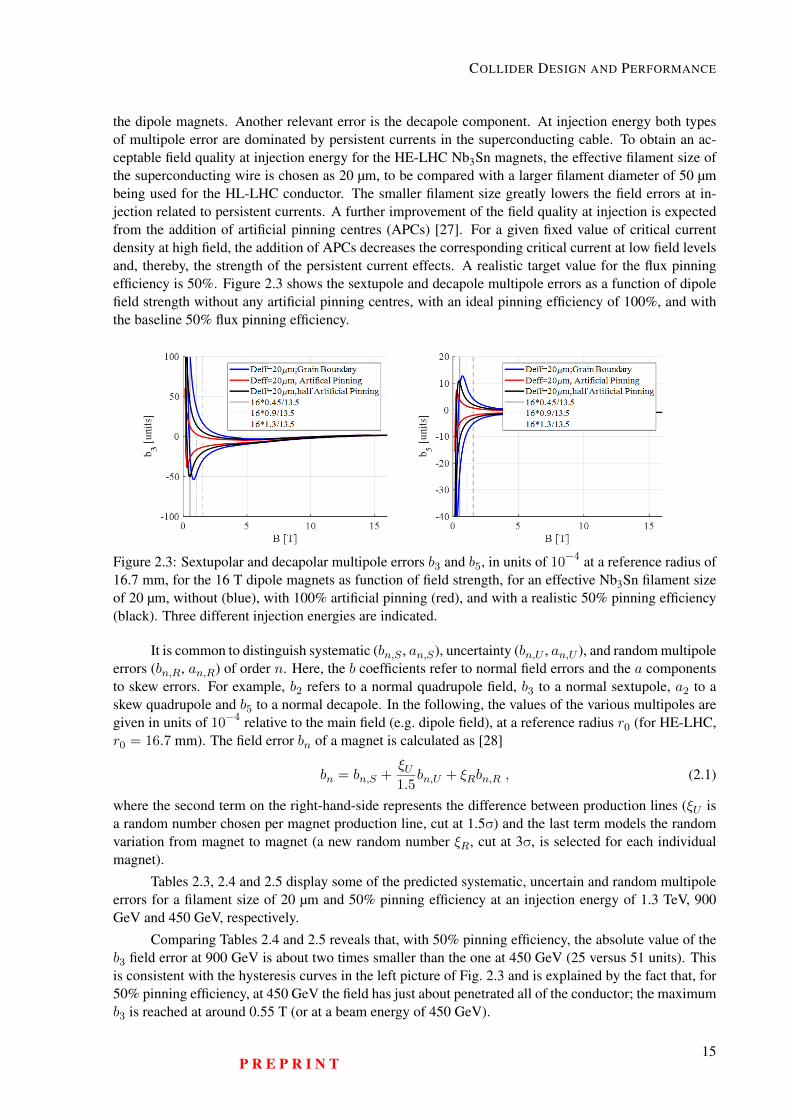
the dipole magnets. Another relevant error is the decapole component. At injection energy both typesof multipole error are dominated by persistent currents in the superconducting cable. To obtain an ac-ceptable field quality at injection energy for the HE-LHC Nb3Sn magnets, the effective filament size ofthe superconducting wire is chosen as 20 µm, to be compared with a larger filament diameter of 50 µmbeing used for the HL-LHC conductor. The smaller filament size greatly lowers the field errors at in-jection related to persistent currents. A further improvement of the field quality at injection is expectedfrom the addition of artificial pinning centres (APCs) [27]. For a given fixed value of critical currentdensity at high field, the addition of APCs decreases the corresponding critical current at low field levelsand, thereby, the strength of the persistent current effects. A realistic target value for the flux pinningefficiency is 50%. Figure 2.3 shows the sextupole and decapole multipole errors as a function of dipolefield strength without any artificial pinning centres, with an ideal pinning efficiency of 100%, and withthe baseline 50% flux pinning efficiency.
Figure 2.3: Sextupolar and decapolar multipole errors b3 and b5, in units of 10−4 at a reference radius of16.7 mm, for the 16 T dipole magnets as function of field strength, for an effective Nb3Sn filament sizeof 20 µm, without (blue), with 100% artificial pinning (red), and with a realistic 50% pinning efficiency(black). Three different injection energies are indicated.
It is common to distinguish systematic (bn,S , an,S), uncertainty (bn,U , an,U ), and random multipoleerrors (bn,R, an,R) of order n. Here, the b coefficients refer to normal field errors and the a componentsto skew errors. For example, b2 refers to a normal quadrupole field, b3 to a normal sextupole, a2 to askew quadrupole and b5 to a normal decapole. In the following, the values of the various multipoles aregiven in units of 10−4 relative to the main field (e.g. dipole field), at a reference radius r0 (for HE-LHC,r0 = 16.7 mm). The field error bn of a magnet is calculated as [28]
bn = bn,S +ξU1.5
bn,U + ξRbn,R , (2.1)
where the second term on the right-hand-side represents the difference between production lines (ξU isa random number chosen per magnet production line, cut at 1.5σ) and the last term models the randomvariation from magnet to magnet (a new random number ξR, cut at 3σ, is selected for each individualmagnet).
Tables 2.3, 2.4 and 2.5 display some of the predicted systematic, uncertain and random multipoleerrors for a filament size of 20 µm and 50% pinning efficiency at an injection energy of 1.3 TeV, 900GeV and 450 GeV, respectively.
Comparing Tables 2.4 and 2.5 reveals that, with 50% pinning efficiency, the absolute value of theb3 field error at 900 GeV is about two times smaller than the one at 450 GeV (25 versus 51 units). Thisis consistent with the hysteresis curves in the left picture of Fig. 2.3 and is explained by the fact that, for50% pinning efficiency, at 450 GeV the field has just about penetrated all of the conductor; the maximumb3 is reached at around 0.55 T (or at a beam energy of 450 GeV).
P R E P R I N T15
HE-LHC Conceptual Design Report (V0.11, 8 November 2018)
Table 2.3: Normal and skew multipole errors in the main arc dipoles up to dodecapole components foran injection energy of 1.3 TeV, in units of 10−4 at a reference radius of 16.7 mm with 20 µm filamentsize and 50% pinning efficiency [29].
multipole systematic uncertainty random multipole systematic uncertainty randomb2 4.79 0.93 0.93 a2 0.00 1.10 1.10b3 −16.20 0.67 0.67 a3 0.00 0.75 0.75b4 0.85 0.47 0.47 a4 0.00 0.47 0.47b5 3.19 0.28 0.28 a5 0.00 0.33 0.33b6 0.54 0.19 0.19 a6 0.00 0.21 0.21
Table 2.4: Normal and skew multipole errors in the main arc dipoles up to dodecapole components foran injection energy of 900 GeV, in units of 10−4 at a reference radius of 16.7 mm with 20 µm filamentsize and 50% pinning efficiency [29].
multipole systematic uncertainty random multipole systematic uncertainty randomb2 5.61 0.93 0.93 a2 0.00 1.10 1.10b3 −24.86 0.67 0.67 a3 0.00 0.75 0.75b4 0.80 0.47 0.47 a4 0.00 0.47 0.47b5 5.11 0.28 0.28 a5 0.00 0.33 0.33b6 0.67 0.19 0.19 a6 0.00 0.21 0.21
Table 2.5: Normal and skew multipole errors in the main arc dipoles up to dodecapole components foran injection energy of 450 GeV, in units of 10−4 at a reference radius of 16.7 mm with 20 µm filamentsize and 50% pinning efficiency [29].
multipole systematic uncertainty random multipole systematic uncertainty randomb2 7.83 0.93 0.93 a2 0.00 1.10 1.10b3 −50.76 0.67 0.67 a3 0.00 0.75 0.75b4 0.64 0.47 0.47 a4 0.00 0.47 0.47b5 12.26 0.28 0.28 a5 0.00 0.33 0.33b6 1.08 0.19 0.19 a6 0.00 0.21 0.21
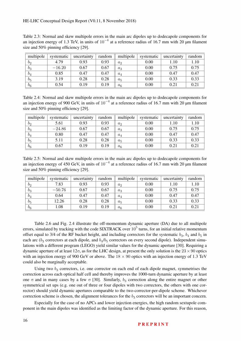
Table 2.6 and Fig. 2.4 illustrate the off-momentum dynamic aperture (DA) due to all multipoleerrors, simulated by tracking with the code SIXTRACK over 105 turns, for an initial relative momentumoffset equal to 3/4 of the RF bucket height, and including correctors for the systematic b3, b4 and b5 ineach arc (b3 correctors at each dipole, and b4/b5 correctors on every second dipole). Independent simu-lations with a different program (LEGO) yield similar values for the dynamic aperture [30]. Requiring adynamic aperture of at least 12σ, as for the LHC design, at present the only solution is the 23×90 opticswith an injection energy of 900 GeV or above. The 18 × 90 optics with an injection energy of 1.3 TeVcould also be marginally acceptable.
Using two b3 correctors, i.e. one corrector on each end of each dipole magnet, symmetrises thecorrection across each optical half cell and thereby improves the 1000-turn dynamic aperture by at leastone σ and in many cases by a few σ [30]. Similarly, b3 correction along the entire magnet or othersymmetrical set ups (e.g. one out of three or four dipoles with two correctors, the others with one cor-rector) should yield dynamic apertures comparable to the two-corrector-per-dipole scheme. Whichevercorrection scheme is chosen, the alignment tolerances for the b3 correctors will be an important concern.
Especially for the case of no APCs and lower injection energies, the high random sextupole com-ponent in the main dipoles was identified as the limiting factor of the dynamic aperture. For this reason,
16P R E P R I N T
COLLIDER DESIGN AND PERFORMANCE
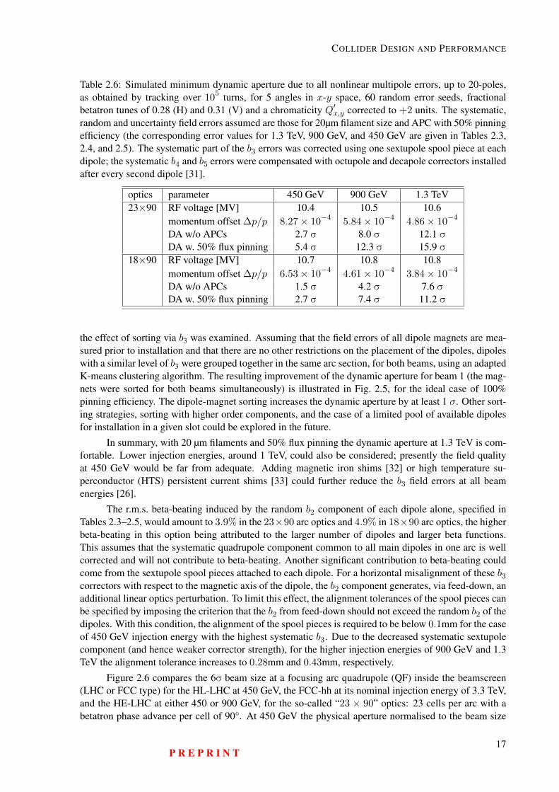
Table 2.6: Simulated minimum dynamic aperture due to all nonlinear multipole errors, up to 20-poles,as obtained by tracking over 105 turns, for 5 angles in x-y space, 60 random error seeds, fractionalbetatron tunes of 0.28 (H) and 0.31 (V) and a chromaticity Q′x,y corrected to +2 units. The systematic,random and uncertainty field errors assumed are those for 20µm filament size and APC with 50% pinningefficiency (the corresponding error values for 1.3 TeV, 900 GeV, and 450 GeV are given in Tables 2.3,2.4, and 2.5). The systematic part of the b3 errors was corrected using one sextupole spool piece at eachdipole; the systematic b4 and b5 errors were compensated with octupole and decapole correctors installedafter every second dipole [31].
optics parameter 450 GeV 900 GeV 1.3 TeV23×90 RF voltage [MV] 10.4 10.5 10.6
momentum offset ∆p/p 8.27× 10⁻⁴ 5.84× 10⁻⁴ 4.86× 10⁻⁴
DA w/o APCs 2.7 σ 8.0 σ 12.1 σDA w. 50% flux pinning 5.4 σ 12.3 σ 15.9 σ
18×90 RF voltage [MV] 10.7 10.8 10.8momentum offset ∆p/p 6.53× 10⁻⁴ 4.61× 10⁻⁴ 3.84× 10⁻⁴
DA w/o APCs 1.5 σ 4.2 σ 7.6 σDA w. 50% flux pinning 2.7 σ 7.4 σ 11.2 σ
the effect of sorting via b3 was examined. Assuming that the field errors of all dipole magnets are mea-sured prior to installation and that there are no other restrictions on the placement of the dipoles, dipoleswith a similar level of b3 were grouped together in the same arc section, for both beams, using an adaptedK-means clustering algorithm. The resulting improvement of the dynamic aperture for beam 1 (the mag-nets were sorted for both beams simultaneously) is illustrated in Fig. 2.5, for the ideal case of 100%pinning efficiency. The dipole-magnet sorting increases the dynamic aperture by at least 1 σ. Other sort-ing strategies, sorting with higher order components, and the case of a limited pool of available dipolesfor installation in a given slot could be explored in the future.
In summary, with 20 µm filaments and 50% flux pinning the dynamic aperture at 1.3 TeV is com-fortable. Lower injection energies, around 1 TeV, could also be considered; presently the field qualityat 450 GeV would be far from adequate. Adding magnetic iron shims [32] or high temperature su-perconductor (HTS) persistent current shims [33] could further reduce the b3 field errors at all beamenergies [26].
The r.m.s. beta-beating induced by the random b2 component of each dipole alone, specified inTables 2.3–2.5, would amount to 3.9% in the 23×90 arc optics and 4.9% in 18×90 arc optics, the higherbeta-beating in this option being attributed to the larger number of dipoles and larger beta functions.This assumes that the systematic quadrupole component common to all main dipoles in one arc is wellcorrected and will not contribute to beta-beating. Another significant contribution to beta-beating couldcome from the sextupole spool pieces attached to each dipole. For a horizontal misalignment of these b3correctors with respect to the magnetic axis of the dipole, the b2 component generates, via feed-down, anadditional linear optics perturbation. To limit this effect, the alignment tolerances of the spool pieces canbe specified by imposing the criterion that the b2 from feed-down should not exceed the random b2 of thedipoles. With this condition, the alignment of the spool pieces is required to be below 0.1mm for the caseof 450 GeV injection energy with the highest systematic b3. Due to the decreased systematic sextupolecomponent (and hence weaker corrector strength), for the higher injection energies of 900 GeV and 1.3TeV the alignment tolerance increases to 0.28mm and 0.43mm, respectively.
Figure 2.6 compares the 6σ beam size at a focusing arc quadrupole (QF) inside the beamscreen(LHC or FCC type) for the HL-LHC at 450 GeV, the FCC-hh at its nominal injection energy of 3.3 TeV,and the HE-LHC at either 450 or 900 GeV, for the so-called “23 × 90” optics: 23 cells per arc with abetatron phase advance per cell of 90°. At 450 GeV the physical aperture normalised to the beam size
P R E P R I N T17
HE-LHC Conceptual Design Report (V0.11, 8 November 2018)
0 2 4 6 8 10 12 14 16Minimum DA
18x90 with 50%
pinning efficiency
23x90 with 50%
pinning efficiency
2.7
5.4
7.4
12.3
11.2
15.9
450 GeV900 GeV1300 GeV
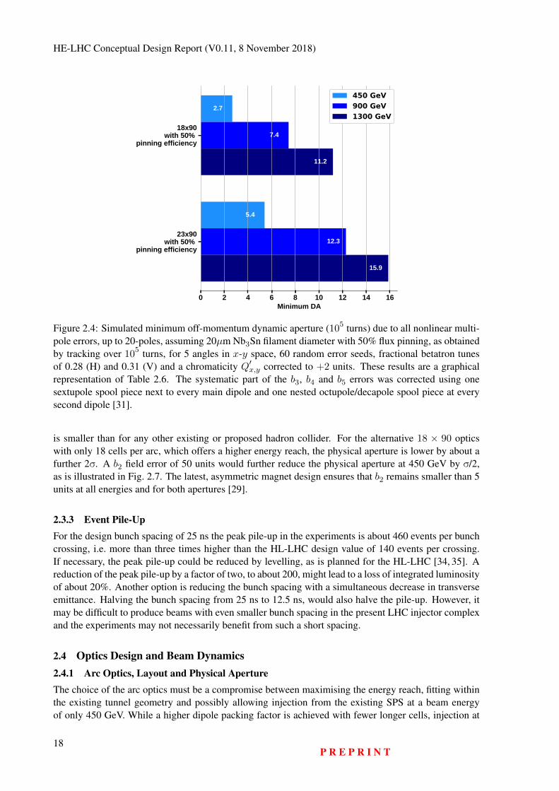
Figure 2.4: Simulated minimum off-momentum dynamic aperture (105 turns) due to all nonlinear multi-pole errors, up to 20-poles, assuming 20µm Nb3Sn filament diameter with 50% flux pinning, as obtainedby tracking over 105 turns, for 5 angles in x-y space, 60 random error seeds, fractional betatron tunesof 0.28 (H) and 0.31 (V) and a chromaticity Q′x,y corrected to +2 units. These results are a graphicalrepresentation of Table 2.6. The systematic part of the b3, b4 and b5 errors was corrected using onesextupole spool piece next to every main dipole and one nested octupole/decapole spool piece at everysecond dipole [31].
is smaller than for any other existing or proposed hadron collider. For the alternative 18 × 90 opticswith only 18 cells per arc, which offers a higher energy reach, the physical aperture is lower by about afurther 2σ. A b2 field error of 50 units would further reduce the physical aperture at 450 GeV by σ/2,as is illustrated in Fig. 2.7. The latest, asymmetric magnet design ensures that b2 remains smaller than 5units at all energies and for both apertures [29].
2.3.3 Event Pile-UpFor the design bunch spacing of 25 ns the peak pile-up in the experiments is about 460 events per bunchcrossing, i.e. more than three times higher than the HL-LHC design value of 140 events per crossing.If necessary, the peak pile-up could be reduced by levelling, as is planned for the HL-LHC [34, 35]. Areduction of the peak pile-up by a factor of two, to about 200, might lead to a loss of integrated luminosityof about 20%. Another option is reducing the bunch spacing with a simultaneous decrease in transverseemittance. Halving the bunch spacing from 25 ns to 12.5 ns, would also halve the pile-up. However, itmay be difficult to produce beams with even smaller bunch spacing in the present LHC injector complexand the experiments may not necessarily benefit from such a short spacing.
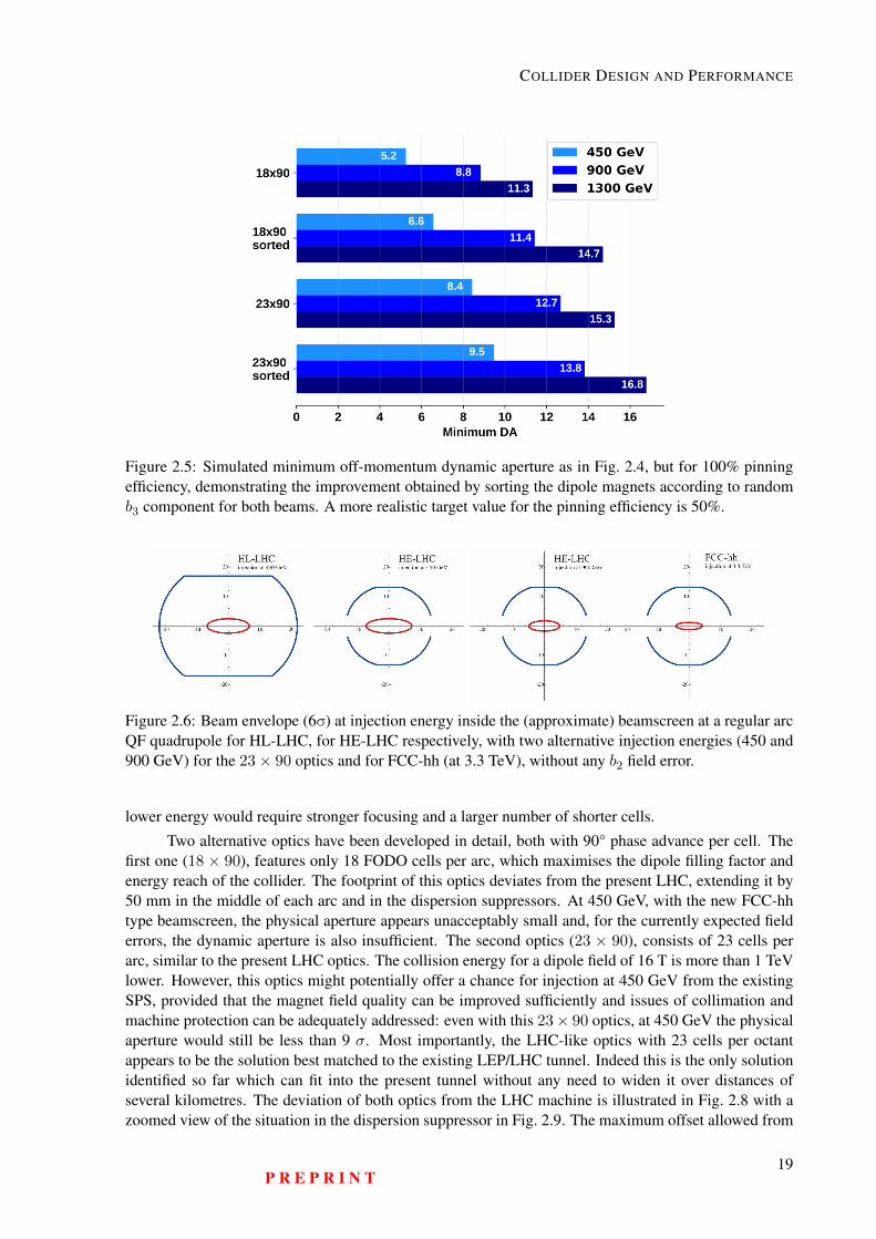
2.4 Optics Design and Beam Dynamics2.4.1 Arc Optics, Layout and Physical ApertureThe choice of the arc optics must be a compromise between maximising the energy reach, fitting withinthe existing tunnel geometry and possibly allowing injection from the existing SPS at a beam energyof only 450 GeV. While a higher dipole packing factor is achieved with fewer longer cells, injection at
18P R E P R I N T
COLLIDER DESIGN AND PERFORMANCE
Figure 2.5: Simulated minimum off-momentum dynamic aperture as in Fig. 2.4, but for 100% pinningefficiency, demonstrating the improvement obtained by sorting the dipole magnets according to randomb3 component for both beams. A more realistic target value for the pinning efficiency is 50%.
Figure 2.6: Beam envelope (6σ) at injection energy inside the (approximate) beamscreen at a regular arcQF quadrupole for HL-LHC, for HE-LHC respectively, with two alternative injection energies (450 and900 GeV) for the 23× 90 optics and for FCC-hh (at 3.3 TeV), without any b2 field error.
lower energy would require stronger focusing and a larger number of shorter cells.
Two alternative optics have been developed in detail, both with 90° phase advance per cell. Thefirst one (18 × 90), features only 18 FODO cells per arc, which maximises the dipole filling factor andenergy reach of the collider. The footprint of this optics deviates from the present LHC, extending it by50 mm in the middle of each arc and in the dispersion suppressors. At 450 GeV, with the new FCC-hhtype beamscreen, the physical aperture appears unacceptably small and, for the currently expected fielderrors, the dynamic aperture is also insufficient. The second optics (23 × 90), consists of 23 cells perarc, similar to the present LHC optics. The collision energy for a dipole field of 16 T is more than 1 TeVlower. However, this optics might potentially offer a chance for injection at 450 GeV from the existingSPS, provided that the magnet field quality can be improved sufficiently and issues of collimation andmachine protection can be adequately addressed: even with this 23× 90 optics, at 450 GeV the physicalaperture would still be less than 9 σ. Most importantly, the LHC-like optics with 23 cells per octantappears to be the solution best matched to the existing LEP/LHC tunnel. Indeed this is the only solutionidentified so far which can fit into the present tunnel without any need to widen it over distances ofseveral kilometres. The deviation of both optics from the LHC machine is illustrated in Fig. 2.8 with azoomed view of the situation in the dispersion suppressor in Fig. 2.9. The maximum offset allowed from
P R E P R I N T19
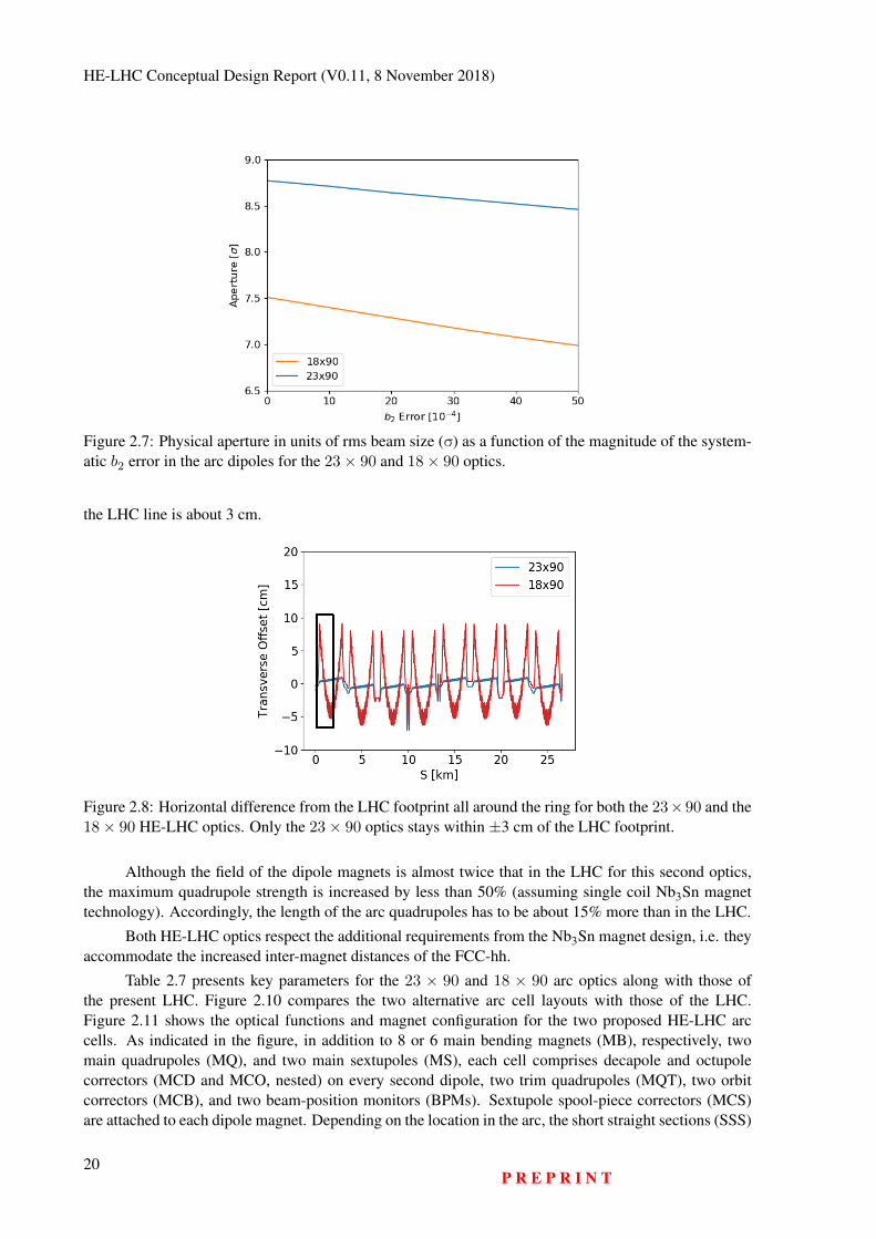
HE-LHC Conceptual Design Report (V0.11, 8 November 2018)
Figure 2.7: Physical aperture in units of rms beam size (σ) as a function of the magnitude of the system-atic b2 error in the arc dipoles for the 23× 90 and 18× 90 optics.
the LHC line is about 3 cm.
Figure 2.8: Horizontal difference from the LHC footprint all around the ring for both the 23×90 and the18× 90 HE-LHC optics. Only the 23× 90 optics stays within ±3 cm of the LHC footprint.
Although the field of the dipole magnets is almost twice that in the LHC for this second optics,the maximum quadrupole strength is increased by less than 50% (assuming single coil Nb3Sn magnettechnology). Accordingly, the length of the arc quadrupoles has to be about 15% more than in the LHC.
Both HE-LHC optics respect the additional requirements from the Nb3Sn magnet design, i.e. theyaccommodate the increased inter-magnet distances of the FCC-hh.
Table 2.7 presents key parameters for the 23 × 90 and 18 × 90 arc optics along with those ofthe present LHC. Figure 2.10 compares the two alternative arc cell layouts with those of the LHC.Figure 2.11 shows the optical functions and magnet configuration for the two proposed HE-LHC arccells. As indicated in the figure, in addition to 8 or 6 main bending magnets (MB), respectively, twomain quadrupoles (MQ), and two main sextupoles (MS), each cell comprises decapole and octupolecorrectors (MCD and MCO, nested) on every second dipole, two trim quadrupoles (MQT), two orbitcorrectors (MCB), and two beam-position monitors (BPMs). Sextupole spool-piece correctors (MCS)are attached to each dipole magnet. Depending on the location in the arc, the short straight sections (SSS)
20P R E P R I N T
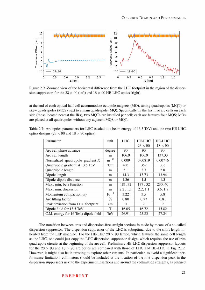
COLLIDER DESIGN AND PERFORMANCE
Figure 2.9: Zoomed view of the horizontal difference from the LHC footprint in the region of the disper-sion suppressor, for the 23× 90 (left) and 18× 90 HE-LHC optics (right).
at the end of each optical half cell accommodate octupole magnets (MO), tuning quadrupoles (MQT) orskew quadrupoles (MQS) next to a main quadrupole (MQ). Specifically, in the first five arc cells on eachside (those located nearest the IRs), two MQTs are installed per cell; each arc features four MQS; MOsare placed at all quadrupoles without any adjacent MQS or MQT.
Table 2.7: Arc optics parameters for LHC (scaled to a beam energy of 13.5 TeV) and the two HE-LHCoptics designs (23× 90 and 18× 90 optics).
Parameter unit LHC HE-LHC HE-LHC23× 90 18× 90
Arc cell phase advance degree 90 90 90Arc cell length m 106.9 106.9 137.33Normalized quadrupole gradient K m−2 0.009 0.00819 0.00746Quadrupole gradient at 13.5 TeV T/m 405 352 336Quadrupole length m 3.1 3.3 2.8Dipole length m 14.3 13.73 13.94Dipole-dipole distance m 1.36 1.5 1.5Max., min. beta function m 181, 32 177 , 32 230, 40Max., min. dispersion m 2.2 , 1.1 2.2, 1.1 3.6, 1.8Momentum compaction αC 10−4 3.22 3.5 5.8Arc filling factor % 0.80 0.77 0.81Peak deviation from LHC footprint cm 0 2 9Dipole field for 13.5 TeV T 16.05 16.72 15.82C.M. energy for 16 Tesla dipole field TeV 26.91 25.83 27.24
The transition between arcs and dispersion-free straight sections is made by means of a so-calleddispersion suppressor. The dispersion suppressor of the LHC is suboptimal due to the short length in-herited from the LEP machine. For the HE-LHC 23 × 90 lattice, which features the same cell lengthas the LHC, one could just copy the LHC dispersion suppressor design, which requires the use of trimquadrupole circuits at the beginning of the arc cell. Preliminary HE-LHC dispersion suppressor layoutsfor the 23 × 90 and 18 × 90 arc optics are compared with those of LHC and HL-LHC in Fig. 2.12.However, it might also be interesting to explore other variants. In particular, to avoid a significant per-formance limitation, collimators should be included at the location of the first dispersion peak in thedispersion suppressors next to the experiment insertions and around the collimation straights, as planned
P R E P R I N T21
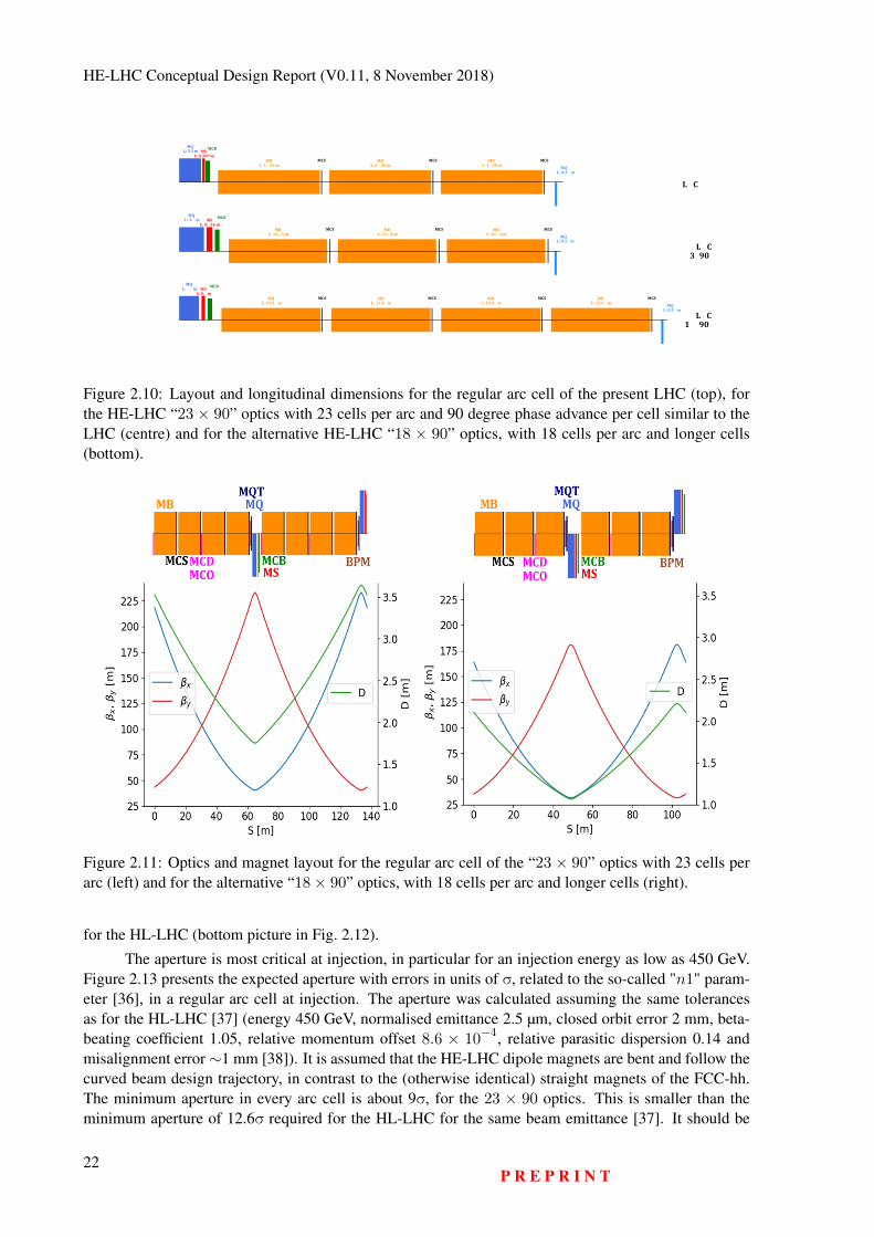
HE-LHC Conceptual Design Report (V0.11, 8 November 2018)
Figure 2.10: Layout and longitudinal dimensions for the regular arc cell of the present LHC (top), forthe HE-LHC “23 × 90” optics with 23 cells per arc and 90 degree phase advance per cell similar to theLHC (centre) and for the alternative HE-LHC “18 × 90” optics, with 18 cells per arc and longer cells(bottom).
Figure 2.11: Optics and magnet layout for the regular arc cell of the “23 × 90” optics with 23 cells perarc (left) and for the alternative “18× 90” optics, with 18 cells per arc and longer cells (right).
for the HL-LHC (bottom picture in Fig. 2.12).
The aperture is most critical at injection, in particular for an injection energy as low as 450 GeV.Figure 2.13 presents the expected aperture with errors in units of σ, related to the so-called "n1" param-eter [36], in a regular arc cell at injection. The aperture was calculated assuming the same tolerancesas for the HL-LHC [37] (energy 450 GeV, normalised emittance 2.5 µm, closed orbit error 2 mm, beta-beating coefficient 1.05, relative momentum offset 8.6 × 10⁻⁴, relative parasitic dispersion 0.14 andmisalignment error∼1 mm [38]). It is assumed that the HE-LHC dipole magnets are bent and follow thecurved beam design trajectory, in contrast to the (otherwise identical) straight magnets of the FCC-hh.The minimum aperture in every arc cell is about 9σ, for the 23 × 90 optics. This is smaller than theminimum aperture of 12.6σ required for the HL-LHC for the same beam emittance [37]. It should be
22P R E P R I N T
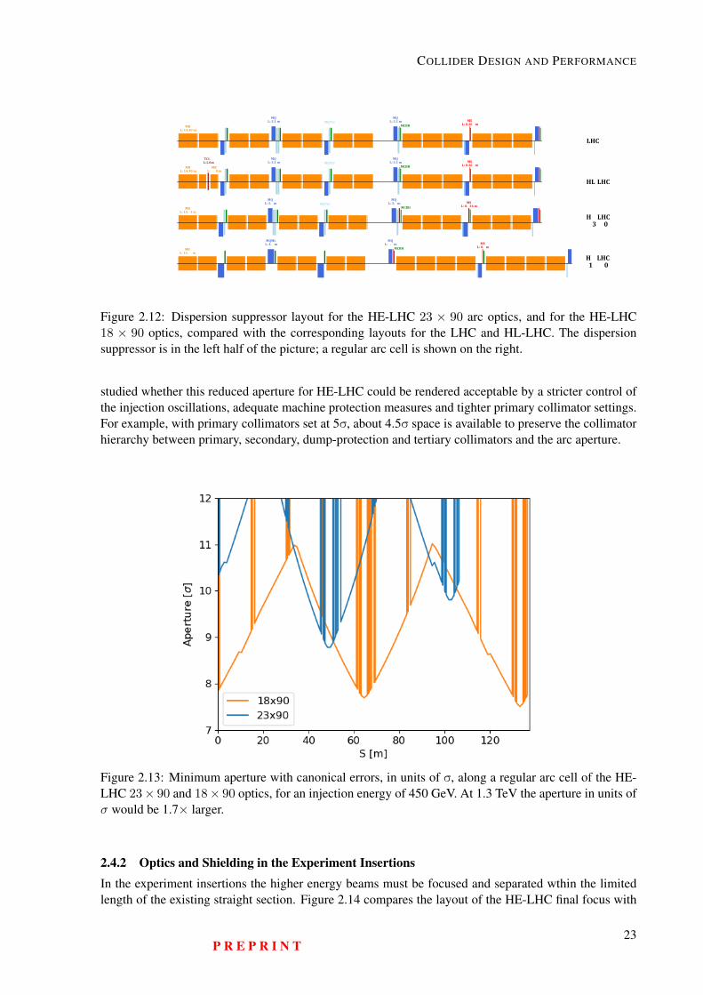
COLLIDER DESIGN AND PERFORMANCE
Figure 2.12: Dispersion suppressor layout for the HE-LHC 23 × 90 arc optics, and for the HE-LHC18 × 90 optics, compared with the corresponding layouts for the LHC and HL-LHC. The dispersionsuppressor is in the left half of the picture; a regular arc cell is shown on the right.
studied whether this reduced aperture for HE-LHC could be rendered acceptable by a stricter control ofthe injection oscillations, adequate machine protection measures and tighter primary collimator settings.For example, with primary collimators set at 5σ, about 4.5σ space is available to preserve the collimatorhierarchy between primary, secondary, dump-protection and tertiary collimators and the arc aperture.
Figure 2.13: Minimum aperture with canonical errors, in units of σ, along a regular arc cell of the HE-LHC 23× 90 and 18× 90 optics, for an injection energy of 450 GeV. At 1.3 TeV the aperture in units ofσ would be 1.7× larger.
2.4.2 Optics and Shielding in the Experiment InsertionsIn the experiment insertions the higher energy beams must be focused and separated wthin the limitedlength of the existing straight section. Figure 2.14 compares the layout of the HE-LHC final focus with
P R E P R I N T23
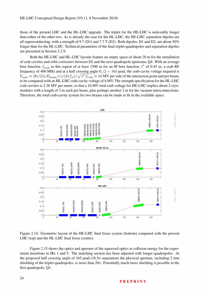
HE-LHC Conceptual Design Report (V0.11, 8 November 2018)
those of the present LHC and the HL-LHC upgrade. The triplet for the HE-LHC is noticeably longerthan either of the other two. As is already the case for the HL-LHC, the HE-LHC separation dipoles areall superconducting, with a strength of 9.7 (D1) and 7.7 T (D2). Both dipoles, D1 and D2, are about 50%longer than for the HL-LHC. Technical parameters of the final triplet quadrupoles and separation dipolesare presented in Section 3.2.9.
Both the HE-LHC and HL-LHC layouts feature an empty space of about 20 m for the installationof crab cavities and orbit correctors between D2 and the next quadrupole upstream, Q4. With an averagebeta function βcrab in this region of at least 1500 m for an IP beta function β∗ of 0.45 m, a crab RFfrequency of 400 MHz and at a half crossing angle θc/2 = 165 µrad, the crab-cavity voltage required isVcrab ≈ (θc/2)(cEbeam/e)/(2πfrf)/
√β∗βcrab ≈ 10 MV per side of the interaction point and per beam,
to be compared with an HL-LHC crab-cavity voltage of 6 MV. The strength specification for the HL-LHCcrab cavities is 2.26 MV per meter, so that a 10 MV total crab voltage for HE-LHC implies about 2 cryo-modules with a length of 3 m each per beam, plus perhaps another 2 m for the vacuum interconnections.Therefore, the total crab-cavity system for two beams can be made to fit in the available space.
0 20 40 60 80 100 120 140 1600
0.05
0.1
0.15
0.2
0.25
0.3LHC
MQ
XA
.1R
5
MQ
XB
.A2R
5
MQ
XB
.B2R
5
MQ
SX
.3R
5
MQ
XA
.3R
5
MB
XW
.A4R
5
MB
XW
.B4R
5
MB
XW
.C4R
5
MB
XW
.D4R
5
MB
XW
.E4R
5
MB
XW
.F4R
5
MB
RC
.4R
5.B
1
MQ
Y.4
R5.B
1
MQ
ML.5
R5.B
1
0 20 40 60 80 100 120 140 1600
0.05
0.1
0.15
0.2
0.25
0.3SLHC V3.1a
MQ
XC
.1R
5
MQ
XD
.A2R
5
MQ
XD
.B2R
5
MQ
XC
.3R
5
MQ
SX
.3R
5
MB
XA
.4R
5
MB
RD
.4R
5.B
1
MQ
YY
.4R
5.B
1
0 20 40 60 80 100 120 140 1600
0.05
0.1
0.15
0.2
0.25
0.3HE LHC
MQ
XC
.1R
5
MQ
XD
.A2R
5
MQ
XD
.B2R
5
MQ
XC
.3R
5
MQ
SX
.3R
5
MB
XA
.4R
5 MB
RD
.4R
5.B
1
MQ
YY
.4R
5.B
1
MQ
YL.5
R5.B
1
Figure 2.14: Geometric layout of the HE-LHC final focus system (bottom) compared with the presentLHC (top) and the HL-LHC final focus (centre).
Figure 2.15 shows the optics and aperture of the squeezed optics at collision energy for the exper-iment insertions in IRs 1 and 5. The matching section has been adjusted with longer quadrupoles. Atthe proposed half crossing angle of 165 µrad (16.5σ separation) the physical aperture, including 2 mmshielding of the triplet quadrupoles, is more than 20σ. Potentially much more shielding is possible in thefirst quadrupole, Q1.
24P R E P R I N T
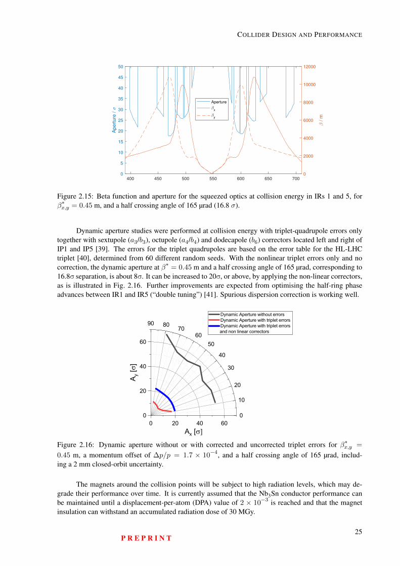
COLLIDER DESIGN AND PERFORMANCE
400 450 500 550 600 650 7000
5
10
15
20
25
30
35
40
45
50
Apert
ure
/
0
2000
4000
6000
8000
10000
12000
/ m
Aperture
x
y
Figure 2.15: Beta function and aperture for the squeezed optics at collision energy in IRs 1 and 5, forβ∗x,y = 0.45 m, and a half crossing angle of 165 µrad (16.8 σ).
Dynamic aperture studies were performed at collision energy with triplet-quadrupole errors onlytogether with sextupole (a3/b3), octupole (a4/b4) and dodecapole (b6) correctors located left and right ofIP1 and IP5 [39]. The errors for the triplet quadrupoles are based on the error table for the HL-LHCtriplet [40], determined from 60 different random seeds. With the nonlinear triplet errors only and nocorrection, the dynamic aperture at β∗ = 0.45 m and a half crossing angle of 165 µrad, corresponding to16.8σ separation, is about 8σ. It can be increased to 20σ, or above, by applying the non-linear correctors,as is illustrated in Fig. 2.16. Further improvements are expected from optimising the half-ring phaseadvances between IR1 and IR5 (“double tuning”) [41]. Spurious dispersion correction is working well.
0
10
20
30
40
5060
708090
0
20
40
60
0 20 40 60Ax [s]
A y [s
]
Dynamic Aperture without errors Dynamic Aperture with triplet errors Dynamic Aperture with triplet errors
and non linear correctors
Figure 2.16: Dynamic aperture without or with corrected and uncorrected triplet errors for β∗x,y =
0.45 m, a momentum offset of ∆p/p = 1.7 × 10⁻⁴, and a half crossing angle of 165 µrad, includ-ing a 2 mm closed-orbit uncertainty.
The magnets around the collision points will be subject to high radiation levels, which may de-grade their performance over time. It is currently assumed that the Nb3Sn conductor performance canbe maintained until a displacement-per-atom (DPA) value of 2 × 10⁻³ is reached and that the magnetinsulation can withstand an accumulated radiation dose of 30 MGy.
P R E P R I N T25
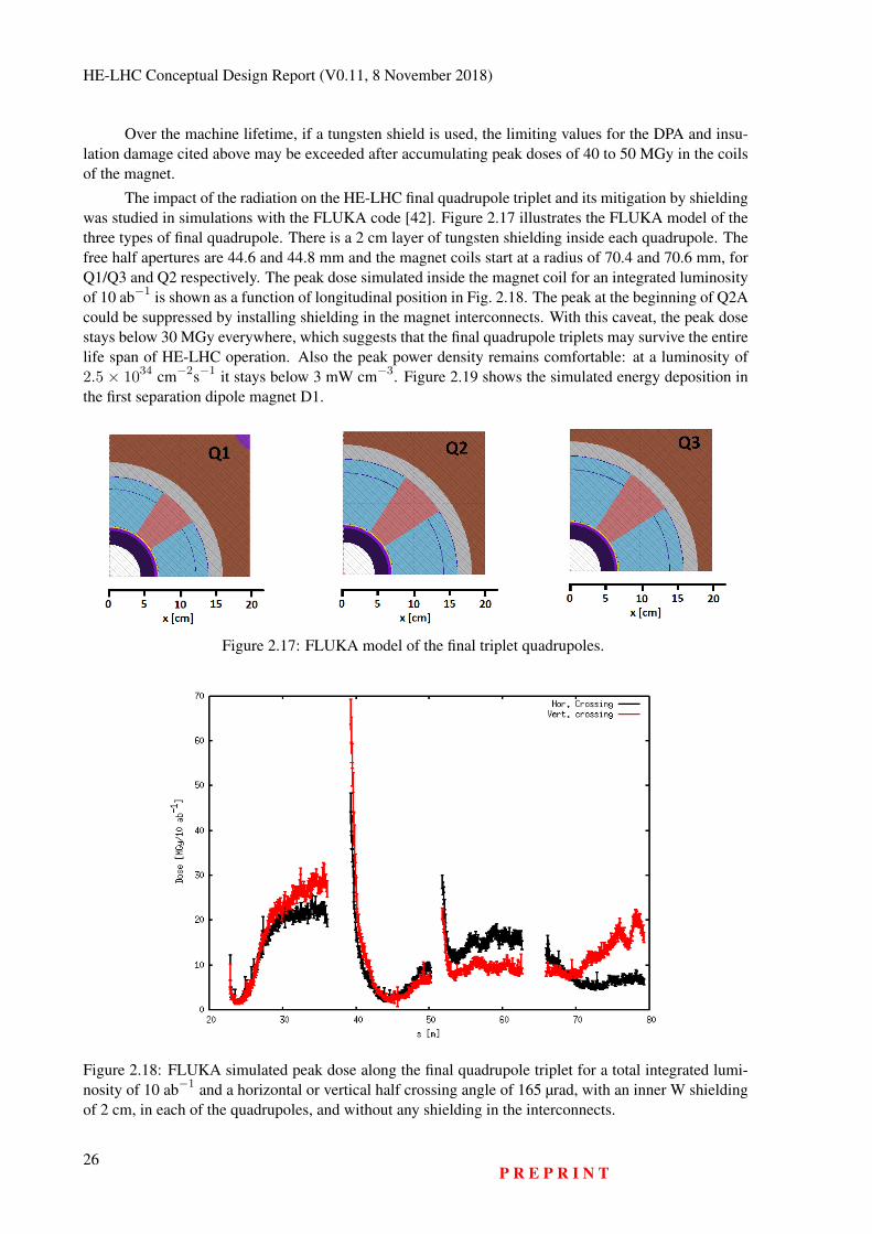
HE-LHC Conceptual Design Report (V0.11, 8 November 2018)
Over the machine lifetime, if a tungsten shield is used, the limiting values for the DPA and insu-lation damage cited above may be exceeded after accumulating peak doses of 40 to 50 MGy in the coilsof the magnet.
The impact of the radiation on the HE-LHC final quadrupole triplet and its mitigation by shieldingwas studied in simulations with the FLUKA code [42]. Figure 2.17 illustrates the FLUKA model of thethree types of final quadrupole. There is a 2 cm layer of tungsten shielding inside each quadrupole. Thefree half apertures are 44.6 and 44.8 mm and the magnet coils start at a radius of 70.4 and 70.6 mm, forQ1/Q3 and Q2 respectively. The peak dose simulated inside the magnet coil for an integrated luminosityof 10 ab−1 is shown as a function of longitudinal position in Fig. 2.18. The peak at the beginning of Q2Acould be suppressed by installing shielding in the magnet interconnects. With this caveat, the peak dosestays below 30 MGy everywhere, which suggests that the final quadrupole triplets may survive the entirelife span of HE-LHC operation. Also the peak power density remains comfortable: at a luminosity of2.5 × 1034 cm−2s−1 it stays below 3 mW cm−3. Figure 2.19 shows the simulated energy deposition inthe first separation dipole magnet D1.
Figure 2.17: FLUKA model of the final triplet quadrupoles.
Figure 2.18: FLUKA simulated peak dose along the final quadrupole triplet for a total integrated lumi-nosity of 10 ab−1 and a horizontal or vertical half crossing angle of 165 µrad, with an inner W shieldingof 2 cm, in each of the quadrupoles, and without any shielding in the interconnects.
26P R E P R I N T
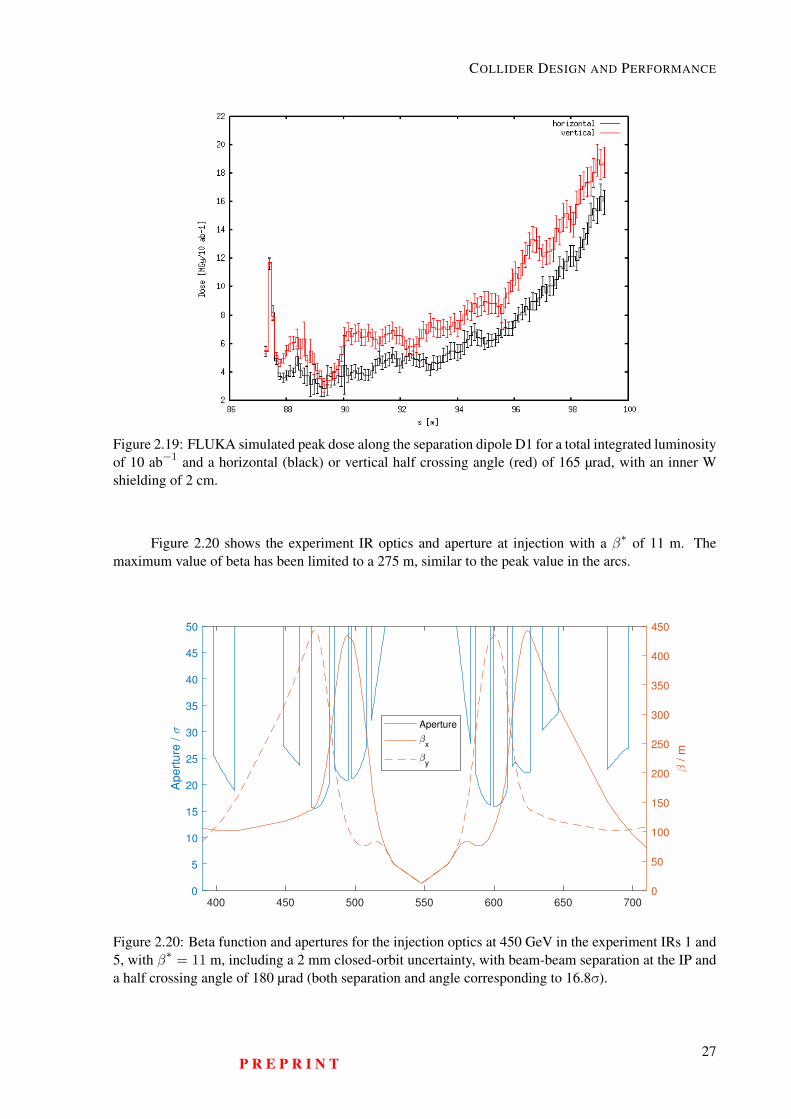
COLLIDER DESIGN AND PERFORMANCE
Figure 2.19: FLUKA simulated peak dose along the separation dipole D1 for a total integrated luminosityof 10 ab−1 and a horizontal (black) or vertical half crossing angle (red) of 165 µrad, with an inner Wshielding of 2 cm.
Figure 2.20 shows the experiment IR optics and aperture at injection with a β∗ of 11 m. Themaximum value of beta has been limited to a 275 m, similar to the peak value in the arcs.
400 450 500 550 600 650 7000
5
10
15
20
25
30
35
40
45
50
Ap
ert
ure
/
0
50
100
150
200
250
300
350
400
450
/ m
Aperture
x
y
Figure 2.20: Beta function and apertures for the injection optics at 450 GeV in the experiment IRs 1 and5, with β∗ = 11 m, including a 2 mm closed-orbit uncertainty, with beam-beam separation at the IP anda half crossing angle of 180 µrad (both separation and angle corresponding to 16.8σ).
P R E P R I N T27
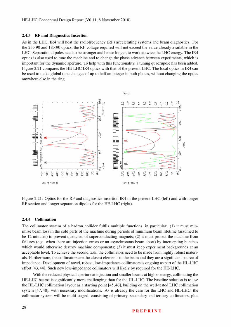
HE-LHC Conceptual Design Report (V0.11, 8 November 2018)
2.4.3 RF and Diagnostics InsertionAs in the LHC, IR4 will host the radiofrequency (RF) accelerating systems and beam diagnostics. Forthe 23×90 and 18×90 optics, the RF voltage required will not exceed the value already available in theLHC. Separation dipoles need to be stronger and hence longer, to work at twice the LHC energy. The IR4optics is also used to tune the machine and to change the phase advance between experiments, which isimportant for the dynamic aperture. To help with this functionality, a tuning quadrupole has been added.Figure 2.21 compares the HE-LHC IR4 optics with that of the present LHC. The local optics in IR4 canbe used to make global tune changes of up to half an integer in both planes, without changing the opticsanywhere else in the ring.
9.4
9.7
10.0
10.3
10.6
s (m
)[*
10
**
( 3
)]
LH
C V
ersi
on
6.5
03
-
July
20
09
0.0
50.
100.
150.
200.
250.
300.
350.
400.
450.
500.
550.
βx(m),βy(m)
βx
βy
0.0
300.
600.
900.
1200.
s
(m
)
IR4
B1
0.0
55.
110.
165.
220.
275.
330.
385.
440.
495.
550.
βx(m),βy(m)
-0.2
0.0
0.2
0.5
0.8
1.0
1.2
1.5
1.8
2.0
2.2
Dx(m)
βx
βy
Dx
Figure 2.21: Optics for the RF and diagnostics insertion IR4 in the present LHC (left) and with longerRF section and longer separation dipoles for the HE-LHC (right).
2.4.4 CollimationThe collimator system of a hadron collider fulfils multiple functions, in particular: (1) it must min-imise beam loss in the cold parts of the machine during periods of minimum beam lifetime (assumed tobe 12 minutes) to prevent quenches of superconducting magnets; (2) it must protect the machine fromfailures (e.g. when there are injection errors or an asynchronous beam abort) by intercepting buncheswhich would otherwise destroy machine components; (3) it must keep experiment backgrounds at anacceptable level. To achieve the second task, the collimators need to be made from highly robust materi-als. Furthermore, the collimators are the closest elements to the beam and they are a significant source ofimpedance. Development of novel, robust, low-impedance collimators is ongoing as part of the HL-LHCeffort [43, 44]. Such new low-impedance collimators will likely by required for the HE-LHC.
With the reduced physical aperture at injection and smaller beams at higher energy, collimating theHE-LHC beams is significantly more challenging than for the HL-LHC. The baseline solution is to usethe HL-LHC collimation layout as a starting point [45, 46], building on the well-tested LHC collimationsystem [47, 48], with necessary modifications. As is already the case for the LHC and HL-LHC, thecollimator system will be multi-staged, consisting of primary, secondary and tertiary collimators, plus
28P R E P R I N T
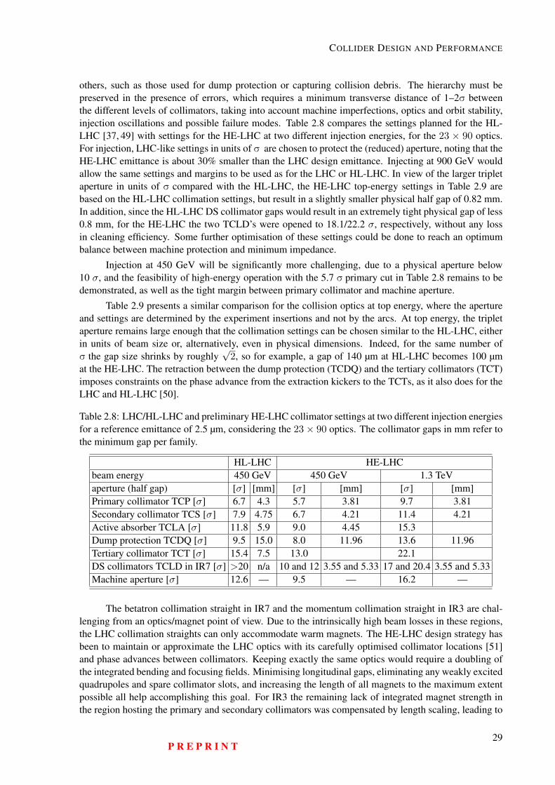
COLLIDER DESIGN AND PERFORMANCE
others, such as those used for dump protection or capturing collision debris. The hierarchy must bepreserved in the presence of errors, which requires a minimum transverse distance of 1–2σ betweenthe different levels of collimators, taking into account machine imperfections, optics and orbit stability,injection oscillations and possible failure modes. Table 2.8 compares the settings planned for the HL-LHC [37, 49] with settings for the HE-LHC at two different injection energies, for the 23 × 90 optics.For injection, LHC-like settings in units of σ are chosen to protect the (reduced) aperture, noting that theHE-LHC emittance is about 30% smaller than the LHC design emittance. Injecting at 900 GeV wouldallow the same settings and margins to be used as for the LHC or HL-LHC. In view of the larger tripletaperture in units of σ compared with the HL-LHC, the HE-LHC top-energy settings in Table 2.9 arebased on the HL-LHC collimation settings, but result in a slightly smaller physical half gap of 0.82 mm.In addition, since the HL-LHC DS collimator gaps would result in an extremely tight physical gap of less0.8 mm, for the HE-LHC the two TCLD’s were opened to 18.1/22.2 σ, respectively, without any lossin cleaning efficiency. Some further optimisation of these settings could be done to reach an optimumbalance between machine protection and minimum impedance.
Injection at 450 GeV will be significantly more challenging, due to a physical aperture below10 σ, and the feasibility of high-energy operation with the 5.7 σ primary cut in Table 2.8 remains to bedemonstrated, as well as the tight margin between primary collimator and machine aperture.
Table 2.9 presents a similar comparison for the collision optics at top energy, where the apertureand settings are determined by the experiment insertions and not by the arcs. At top energy, the tripletaperture remains large enough that the collimation settings can be chosen similar to the HL-LHC, eitherin units of beam size or, alternatively, even in physical dimensions. Indeed, for the same number ofσ the gap size shrinks by roughly
√2, so for example, a gap of 140 µm at HL-LHC becomes 100 µm
at the HE-LHC. The retraction between the dump protection (TCDQ) and the tertiary collimators (TCT)imposes constraints on the phase advance from the extraction kickers to the TCTs, as it also does for theLHC and HL-LHC [50].
Table 2.8: LHC/HL-LHC and preliminary HE-LHC collimator settings at two different injection energiesfor a reference emittance of 2.5 µm, considering the 23× 90 optics. The collimator gaps in mm refer tothe minimum gap per family.
HL-LHC HE-LHCbeam energy 450 GeV 450 GeV 1.3 TeVaperture (half gap) [σ] [mm] [σ] [mm] [σ] [mm]Primary collimator TCP [σ] 6.7 4.3 5.7 3.81 9.7 3.81Secondary collimator TCS [σ] 7.9 4.75 6.7 4.21 11.4 4.21Active absorber TCLA [σ] 11.8 5.9 9.0 4.45 15.3Dump protection TCDQ [σ] 9.5 15.0 8.0 11.96 13.6 11.96Tertiary collimator TCT [σ] 15.4 7.5 13.0 22.1DS collimators TCLD in IR7 [σ] >20 n/a 10 and 12 3.55 and 5.33 17 and 20.4 3.55 and 5.33Machine aperture [σ] 12.6 — 9.5 — 16.2 —
The betatron collimation straight in IR7 and the momentum collimation straight in IR3 are chal-lenging from an optics/magnet point of view. Due to the intrinsically high beam losses in these regions,the LHC collimation straights can only accommodate warm magnets. The HE-LHC design strategy hasbeen to maintain or approximate the LHC optics with its carefully optimised collimator locations [51]and phase advances between collimators. Keeping exactly the same optics would require a doubling ofthe integrated bending and focusing fields. Minimising longitudinal gaps, eliminating any weakly excitedquadrupoles and spare collimator slots, and increasing the length of all magnets to the maximum extentpossible all help accomplishing this goal. For IR3 the remaining lack of integrated magnet strength inthe region hosting the primary and secondary collimators was compensated by length scaling, leading to
P R E P R I N T29
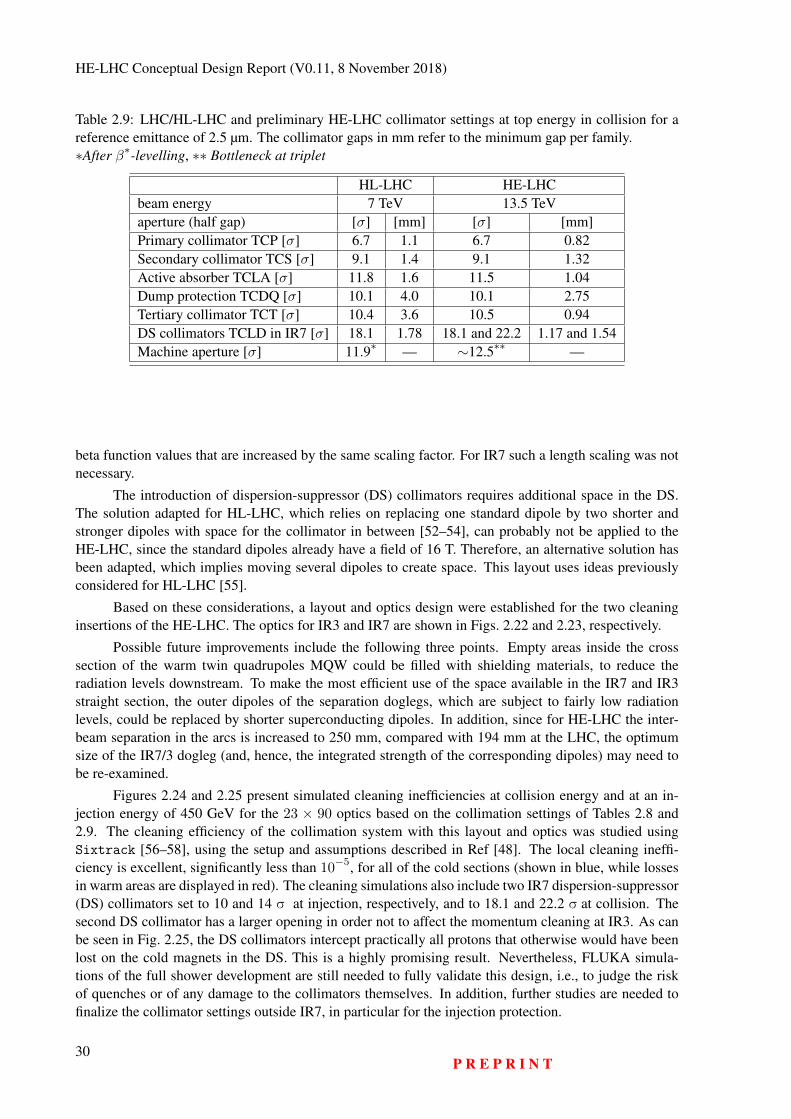
HE-LHC Conceptual Design Report (V0.11, 8 November 2018)
Table 2.9: LHC/HL-LHC and preliminary HE-LHC collimator settings at top energy in collision for areference emittance of 2.5 µm. The collimator gaps in mm refer to the minimum gap per family.∗After β∗-levelling, ∗∗ Bottleneck at triplet
HL-LHC HE-LHCbeam energy 7 TeV 13.5 TeVaperture (half gap) [σ] [mm] [σ] [mm]Primary collimator TCP [σ] 6.7 1.1 6.7 0.82Secondary collimator TCS [σ] 9.1 1.4 9.1 1.32Active absorber TCLA [σ] 11.8 1.6 11.5 1.04Dump protection TCDQ [σ] 10.1 4.0 10.1 2.75Tertiary collimator TCT [σ] 10.4 3.6 10.5 0.94DS collimators TCLD in IR7 [σ] 18.1 1.78 18.1 and 22.2 1.17 and 1.54Machine aperture [σ] 11.9∗ — ∼12.5∗∗ —
beta function values that are increased by the same scaling factor. For IR7 such a length scaling was notnecessary.
The introduction of dispersion-suppressor (DS) collimators requires additional space in the DS.The solution adapted for HL-LHC, which relies on replacing one standard dipole by two shorter andstronger dipoles with space for the collimator in between [52–54], can probably not be applied to theHE-LHC, since the standard dipoles already have a field of 16 T. Therefore, an alternative solution hasbeen adapted, which implies moving several dipoles to create space. This layout uses ideas previouslyconsidered for HL-LHC [55].
Based on these considerations, a layout and optics design were established for the two cleaninginsertions of the HE-LHC. The optics for IR3 and IR7 are shown in Figs. 2.22 and 2.23, respectively.
Possible future improvements include the following three points. Empty areas inside the crosssection of the warm twin quadrupoles MQW could be filled with shielding materials, to reduce theradiation levels downstream. To make the most efficient use of the space available in the IR7 and IR3straight section, the outer dipoles of the separation doglegs, which are subject to fairly low radiationlevels, could be replaced by shorter superconducting dipoles. In addition, since for HE-LHC the inter-beam separation in the arcs is increased to 250 mm, compared with 194 mm at the LHC, the optimumsize of the IR7/3 dogleg (and, hence, the integrated strength of the corresponding dipoles) may need tobe re-examined.
Figures 2.24 and 2.25 present simulated cleaning inefficiencies at collision energy and at an in-jection energy of 450 GeV for the 23 × 90 optics based on the collimation settings of Tables 2.8 and2.9. The cleaning efficiency of the collimation system with this layout and optics was studied usingSixtrack [56–58], using the setup and assumptions described in Ref [48]. The local cleaning ineffi-ciency is excellent, significantly less than 10−5, for all of the cold sections (shown in blue, while lossesin warm areas are displayed in red). The cleaning simulations also include two IR7 dispersion-suppressor(DS) collimators set to 10 and 14 σ at injection, respectively, and to 18.1 and 22.2 σ at collision. Thesecond DS collimator has a larger opening in order not to affect the momentum cleaning at IR3. As canbe seen in Fig. 2.25, the DS collimators intercept practically all protons that otherwise would have beenlost on the cold magnets in the DS. This is a highly promising result. Nevertheless, FLUKA simula-tions of the full shower development are still needed to fully validate this design, i.e., to judge the riskof quenches or of any damage to the collimators themselves. In addition, further studies are needed tofinalize the collimator settings outside IR7, in particular for the injection protection.
30P R E P R I N T
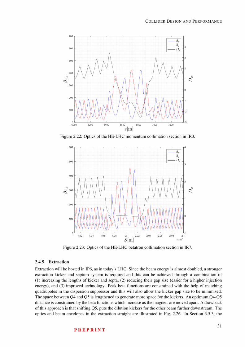
COLLIDER DESIGN AND PERFORMANCE
6000 6200 6400 6600 6800 7000 7200
s[m]
0
100
200
300
400
500
600
700
βx,y
-3
-2
-1
0
1
2
3
4
Dx
βx
βy
Dx
Figure 2.22: Optics of the HE-LHC momentum collimation section in IR3.
1.92 1.94 1.96 1.98 2 2.02 2.04 2.06 2.08 2.1
S[m] ×104
0
100
200
300
400
500
600
βx,y
-1
0
1
2
3
4
Dx
βx
βy
Dx
Figure 2.23: Optics of the HE-LHC betatron collimation section in IR7.
2.4.5 ExtractionExtraction will be hosted in IP6, as in today’s LHC. Since the beam energy is almost doubled, a strongerextraction kicker and septum system is required and this can be achieved through a combination of(1) increasing the lengths of kicker and septa, (2) reducing their gap size (easier for a higher injectionenergy), and (3) improved technology. Peak beta functions are constrained with the help of matchingquadrupoles in the dispersion suppressor and this will also allow the kicker gap size to be minimised.The space between Q4 and Q5 is lengthened to generate more space for the kickers. An optimum Q4-Q5distance is constrained by the beta functions which increase as the magnets are moved apart. A drawbackof this approach is that shifting Q5, puts the dilution kickers for the other beam further downstream. Theoptics and beam envelopes in the extraction straight are illustrated in Fig. 2.26. In Section 3.5.3, the
P R E P R I N T31
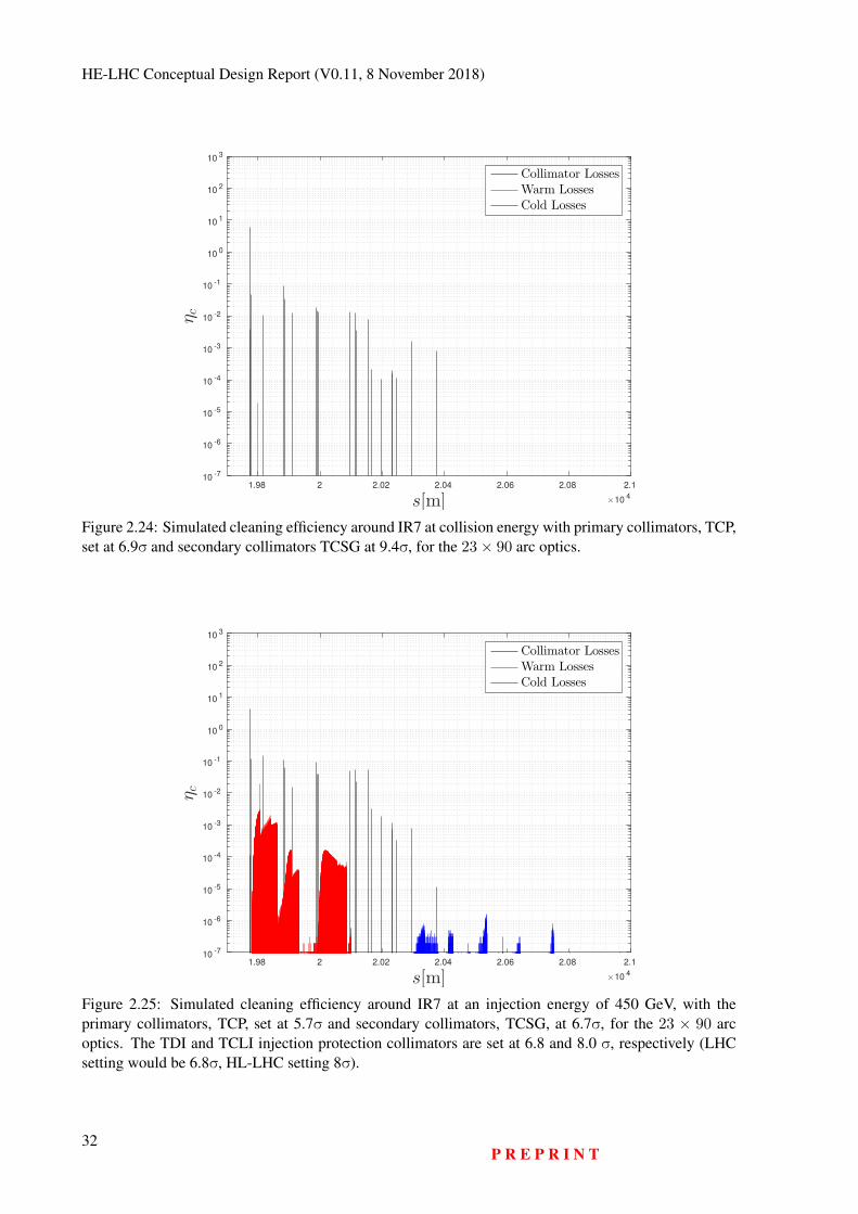
HE-LHC Conceptual Design Report (V0.11, 8 November 2018)
1.98 2 2.02 2.04 2.06 2.08 2.1
s[m] ×104
10-7
10-6
10-5
10-4
10-3
10-2
10-1
100
101
102
103
ηc
Collimator LossesWarm LossesCold Losses
Figure 2.24: Simulated cleaning efficiency around IR7 at collision energy with primary collimators, TCP,set at 6.9σ and secondary collimators TCSG at 9.4σ, for the 23× 90 arc optics.
1.98 2 2.02 2.04 2.06 2.08 2.1
s[m] ×104
10-7
10-6
10-5
10-4
10-3
10-2
10-1
100
101
102
103
ηc
Collimator LossesWarm LossesCold Losses
Figure 2.25: Simulated cleaning efficiency around IR7 at an injection energy of 450 GeV, with theprimary collimators, TCP, set at 5.7σ and secondary collimators, TCSG, at 6.7σ, for the 23 × 90 arcoptics. The TDI and TCLI injection protection collimators are set at 6.8 and 8.0 σ, respectively (LHCsetting would be 6.8σ, HL-LHC setting 8σ).
32P R E P R I N T
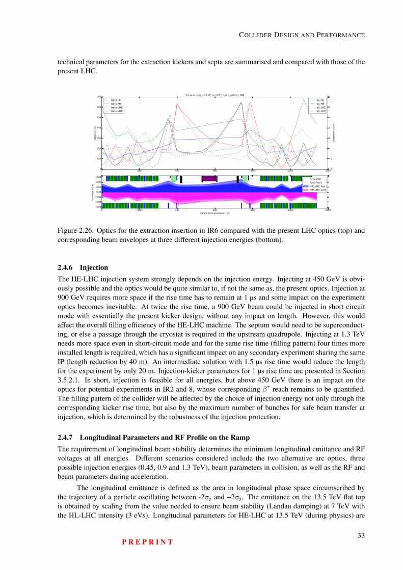
COLLIDER DESIGN AND PERFORMANCE
technical parameters for the extraction kickers and septa are summarised and compared with those of thepresent LHC.
0 200 400 600 800 1000 12000
100
200
300
400
500
600
700B
eta
s in
[m
]
betx-HEbety-HEbetx-LHCbety-LHC
2
1
0
1
2
3
4
5
Dis
pers
ion in [
m]
Comparison HE-LHC vs LHC (run II optics), IR6
dx-HEdy-HEdx-LHCdy-LHC
0 200 400 600 800 1000 1200Longitudinal position in [m]
0.03
0.02
0.01
0.00
0.01
0.02
0.03
Envelo
pe in [
m]
LHC-HorLHC-VertHE-LHC horHE-LHC vert
Figure 2.26: Optics for the extraction insertion in IR6 compared with the present LHC optics (top) andcorresponding beam envelopes at three different injection energies (bottom).
2.4.6 InjectionThe HE-LHC injection system strongly depends on the injection energy. Injecting at 450 GeV is obvi-ously possible and the optics would be quite similar to, if not the same as, the present optics. Injection at900 GeV requires more space if the rise time has to remain at 1 µs and some impact on the experimentoptics becomes inevitable. At twice the rise time, a 900 GeV beam could be injected in short circuitmode with essentially the present kicker design, without any impact on length. However, this wouldaffect the overall filling efficiency of the HE-LHC machine. The septum would need to be superconduct-ing, or else a passage through the cryostat is required in the upstream quadrupole. Injecting at 1.3 TeVneeds more space even in short-circuit mode and for the same rise time (filling pattern) four times moreinstalled length is required, which has a significant impact on any secondary experiment sharing the sameIP (length reduction by 40 m). An intermediate solution with 1.5 µs rise time would reduce the lengthfor the experiment by only 20 m. Injection-kicker parameters for 1 µs rise time are presented in Section3.5.2.1. In short, injection is feasible for all energies, but above 450 GeV there is an impact on theoptics for potential experiments in IR2 and 8, whose corresponding β∗ reach remains to be quantified.The filling pattern of the collider will be affected by the choice of injection energy not only through thecorresponding kicker rise time, but also by the maximum number of bunches for safe beam transfer atinjection, which is determined by the robustness of the injection protection.
2.4.7 Longitudinal Parameters and RF Profile on the RampThe requirement of longitudinal beam stability determines the minimum longitudinal emittance and RFvoltages at all energies. Different scenarios considered include the two alternative arc optics, threepossible injection energies (0.45, 0.9 and 1.3 TeV), beam parameters in collision, as well as the RF andbeam parameters during acceleration.
The longitudinal emittance is defined as the area in longitudinal phase space circumscribed bythe trajectory of a particle oscillating between -2σz and +2σz. The emittance on the 13.5 TeV flat topis obtained by scaling from the value needed to ensure beam stability (Landau damping) at 7 TeV withthe HL-LHC intensity (3 eVs). Longitudinal parameters for HE-LHC at 13.5 TeV (during physics) are
P R E P R I N T33
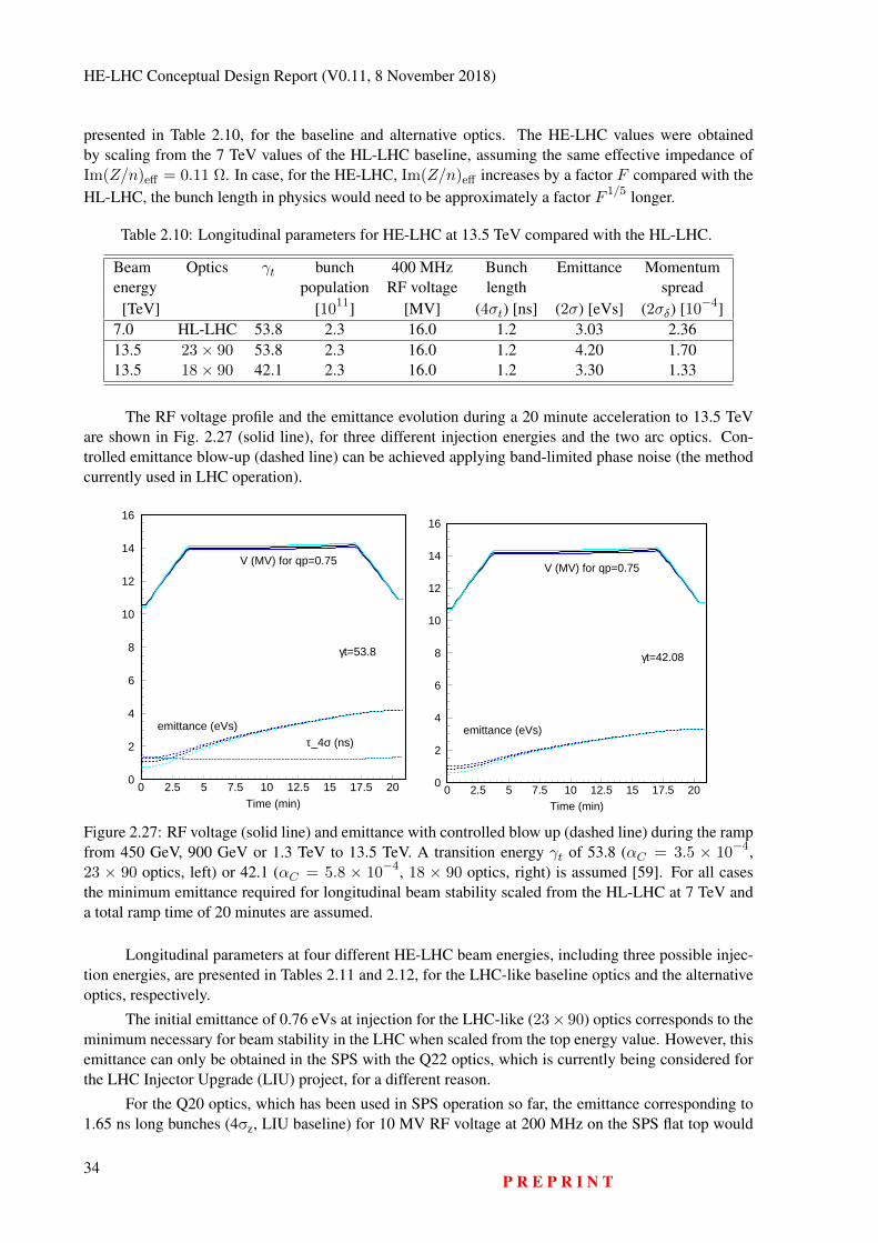
HE-LHC Conceptual Design Report (V0.11, 8 November 2018)
presented in Table 2.10, for the baseline and alternative optics. The HE-LHC values were obtainedby scaling from the 7 TeV values of the HL-LHC baseline, assuming the same effective impedance ofIm(Z/n)eff = 0.11 Ω. In case, for the HE-LHC, Im(Z/n)eff increases by a factor F compared with theHL-LHC, the bunch length in physics would need to be approximately a factor F 1/5 longer.
Table 2.10: Longitudinal parameters for HE-LHC at 13.5 TeV compared with the HL-LHC.
Beam Optics γt bunch 400 MHz Bunch Emittance Momentumenergy population RF voltage length spread
[TeV] [1011] [MV] (4σt) [ns] (2σ) [eVs] (2σδ) [10−4]7.0 HL-LHC 53.8 2.3 16.0 1.2 3.03 2.3613.5 23× 90 53.8 2.3 16.0 1.2 4.20 1.7013.5 18× 90 42.1 2.3 16.0 1.2 3.30 1.33
The RF voltage profile and the emittance evolution during a 20 minute acceleration to 13.5 TeVare shown in Fig. 2.27 (solid line), for three different injection energies and the two arc optics. Con-trolled emittance blow-up (dashed line) can be achieved applying band-limited phase noise (the methodcurrently used in LHC operation).
0
2
4
6
8
10
12
14
16
0 2.5 5 7.5 10 12.5 15 17.5 20Time (min)
τ_4σ (ns)
γt=53.8
V (MV) for qp=0.75
emittance (eVs)
0
2
4
6
8
10
12
14
16
0 2.5 5 7.5 10 12.5 15 17.5 20Time (min)
γt=42.08
V (MV) for qp=0.75
emittance (eVs)
Figure 2.27: RF voltage (solid line) and emittance with controlled blow up (dashed line) during the rampfrom 450 GeV, 900 GeV or 1.3 TeV to 13.5 TeV. A transition energy γt of 53.8 (αC = 3.5 × 10−4,23 × 90 optics, left) or 42.1 (αC = 5.8 × 10⁻⁴, 18 × 90 optics, right) is assumed [59]. For all casesthe minimum emittance required for longitudinal beam stability scaled from the HL-LHC at 7 TeV anda total ramp time of 20 minutes are assumed.
Longitudinal parameters at four different HE-LHC beam energies, including three possible injec-tion energies, are presented in Tables 2.11 and 2.12, for the LHC-like baseline optics and the alternativeoptics, respectively.
The initial emittance of 0.76 eVs at injection for the LHC-like (23× 90) optics corresponds to theminimum necessary for beam stability in the LHC when scaled from the top energy value. However, thisemittance can only be obtained in the SPS with the Q22 optics, which is currently being considered forthe LHC Injector Upgrade (LIU) project, for a different reason.
For the Q20 optics, which has been used in SPS operation so far, the emittance corresponding to1.65 ns long bunches (4σz, LIU baseline) for 10 MV RF voltage at 200 MHz on the SPS flat top would
34P R E P R I N T
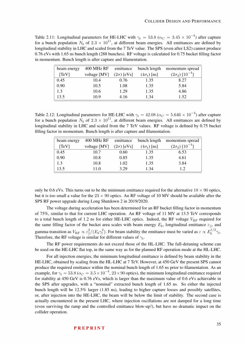
COLLIDER DESIGN AND PERFORMANCE
Table 2.11: Longitudinal parameters for HE-LHC with γt = 53.8 (αC = 3.45 × 10⁻⁴) after capturefor a bunch population Nb of 2.3 × 10¹¹, at different beam energies. All emittances are defined bylongitudinal stability in LHC and scaled from the 7 TeV value. The SPS (even after LS2) cannot produce0.76 eVs with 1.65 ns bunch length (288 bunches). RF voltage is calculated for 0.75 bucket filling factorin momentum. Bunch length is after capture and filamentation.
beam energy 400 MHz RF emittance bunch length momentum spread[TeV] voltage [MV] (2σ) [eVs] (4σt) [ns] (2σδ) [10−4]
0.45 10.4 0.76 1.35 8.270.90 10.5 1.08 1.35 5.841.3 10.6 1.29 1.35 4.8613.5 10.9 4.16 1.34 1.52
Table 2.12: Longitudinal parameters for HE-LHC with γt = 42.08 (αC = 5.646 × 10⁻⁴) after capturefor a bunch population Nb of 2.3 × 10¹¹, at different beam energies. All emittances are defined bylongitudinal stability in LHC and scaled from the 7 TeV values. RF voltage is defined by 0.75 bucketfilling factor in momentum. Bunch length is after capture and filamentation.
beam energy 400 MHz RF emittance bunch length momentum spread[TeV] voltage [MV] (2σ) [eVs] (4σt) [ns] (2σδ) [10−4]
0.45 10.7 0.60 1.35 6.530.90 10.8 0.85 1.35 4.611.3 10.8 1.02 1.35 3.8413.5 11.0 3.29 1.34 1.2
only be 0.6 eVs. This turns out to be the minimum emittance required for the alternative 18× 90 optics,but it is too small a value for the 23 × 90 optics. An RF voltage of 10 MV should be available after theSPS RF power upgrade during Long Shutdown 2 in 2019/2020.
The voltage during acceleration has been determined for an RF bucket filling factor in momentumof 75%, similar to that for current LHC operation. An RF voltage of 11 MV at 13.5 TeV correspondsto a total bunch length of 1.2 ns for either HE-LHC optics. Indeed, the RF voltage VRF required forthe same filling factor of the bucket area scales with beam energy Eb, longitudinal emittance ε||, and
gamma-transition as VRF ∝ ε2||/(Ebγ
2t ). For beam stability the emittance must be varied as ε ∝ E1/2
b γt.Therefore, the RF voltage is similar for different values of γt.
The RF power requirements do not exceed those of the HL-LHC. The full-detuning scheme canbe used on the HE-LHC flat top, in the same way as for the planned RF operation mode at the HL-LHC.
For all injection energies, the minimum longitudinal emittance is defined by beam stability in theHE-LHC, obtained by scaling from the HL-LHC at 7 TeV. However, at 450 GeV the present SPS cannotproduce the required emittance within the nominal bunch length of 1.65 ns prior to filamentation. As anexample, for γt = 53.8 (αC = 3.5×10⁻⁴, 23×90 optics), the minimum longitudinal emittance requiredfor stability at 450 GeV is 0.76 eVs, which is larger than the maximum value of 0.6 eVs achievable inthe SPS after upgrades, with a “nominal” extracted bunch length of 1.65 ns. So either the injectedbunch length will be 12.5% larger (1.85 ns), leading to higher capture losses and possibly satellites,or, after injection into the HE-LHC, the beam will be below the limit of stability. The second case isactually encountered in the present LHC, where injection oscillations are not damped for a long time(even surviving the ramp and the controlled emittance blow-up!), but have no dramatic impact on thecollider operation.
P R E P R I N T35
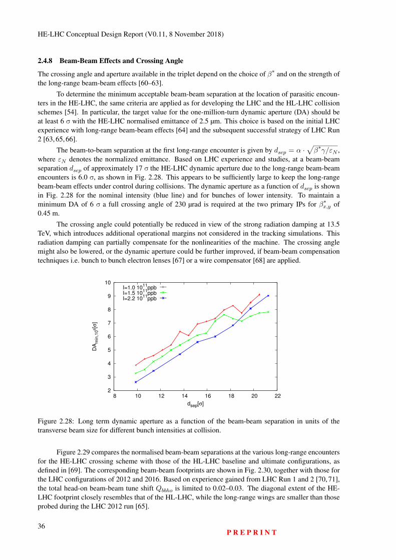
HE-LHC Conceptual Design Report (V0.11, 8 November 2018)
2.4.8 Beam-Beam Effects and Crossing Angle
The crossing angle and aperture available in the triplet depend on the choice of β∗ and on the strength ofthe long-range beam-beam effects [60–63].
To determine the minimum acceptable beam-beam separation at the location of parasitic encoun-ters in the HE-LHC, the same criteria are applied as for developing the LHC and the HL-LHC collisionschemes [54]. In particular, the target value for the one-million-turn dynamic aperture (DA) should beat least 6 σ with the HE-LHC normalised emittance of 2.5 µm. This choice is based on the initial LHCexperience with long-range beam-beam effects [64] and the subsequent successful strategy of LHC Run2 [63, 65, 66].
The beam-to-beam separation at the first long-range encounter is given by dsep = α ·√β∗γ/εN ,
where εN denotes the normalized emittance. Based on LHC experience and studies, at a beam-beamseparation dsep of approximately 17 σ the HE-LHC dynamic aperture due to the long-range beam-beamencounters is 6.0 σ, as shown in Fig. 2.28. This appears to be sufficiently large to keep the long-rangebeam-beam effects under control during collisions. The dynamic aperture as a function of dsep is shownin Fig. 2.28 for the nominal intensity (blue line) and for bunches of lower intensity. To maintain aminimum DA of 6 σ a full crossing angle of 230 µrad is required at the two primary IPs for β∗x,y of0.45 m.
The crossing angle could potentially be reduced in view of the strong radiation damping at 13.5TeV, which introduces additional operational margins not considered in the tracking simulations. Thisradiation damping can partially compensate for the nonlinearities of the machine. The crossing anglemight also be lowered, or the dynamic aperture could be further improved, if beam-beam compensationtechniques i.e. bunch to bunch electron lenses [67] or a wire compensator [68] are applied.
2
3
4
5
6
7
8
9
10
8 10 12 14 16 18 20 22
DA
min
,10
6[σ
]
dsep[σ]
I=1.0 1011
ppbI=1.5 10
11ppb
I=2.2 1011
ppb
Figure 2.28: Long term dynamic aperture as a function of the beam-beam separation in units of thetransverse beam size for different bunch intensities at collision.
Figure 2.29 compares the normalised beam-beam separations at the various long-range encountersfor the HE-LHC crossing scheme with those of the HL-LHC baseline and ultimate configurations, asdefined in [69]. The corresponding beam-beam footprints are shown in Fig. 2.30, together with those forthe LHC configurations of 2012 and 2016. Based on experience gained from LHC Run 1 and 2 [70, 71],the total head-on beam-beam tune shift Qbbho is limited to 0.02–0.03. The diagonal extent of the HE-LHC footprint closely resembles that of the HL-LHC, while the long-range wings are smaller than thoseprobed during the LHC 2012 run [65].
36P R E P R I N T
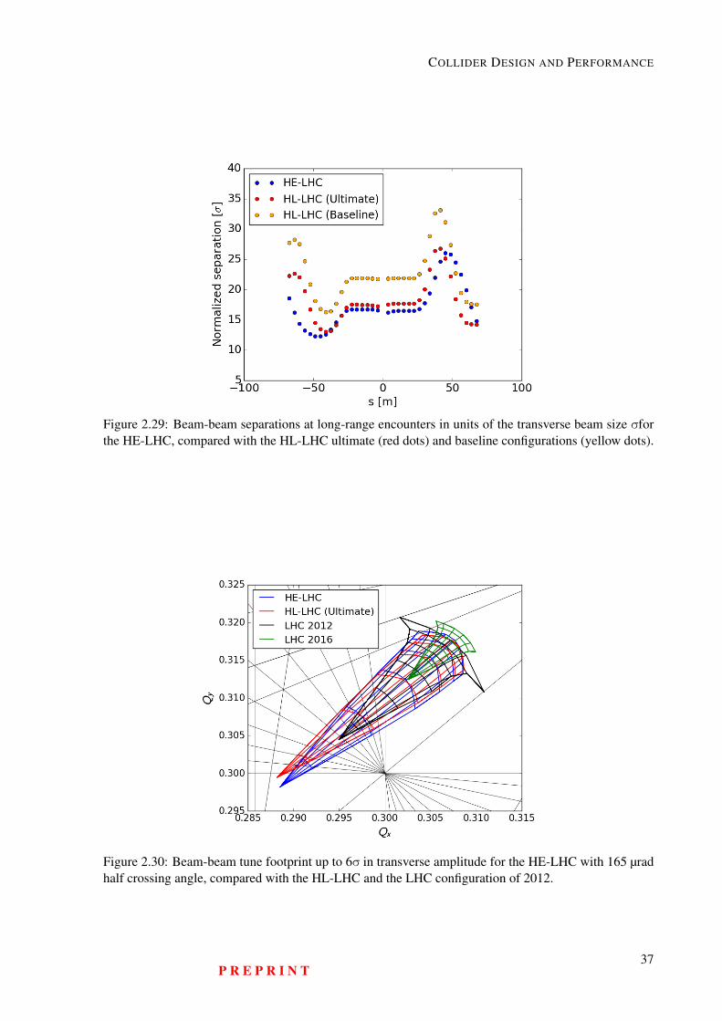
COLLIDER DESIGN AND PERFORMANCE
Figure 2.29: Beam-beam separations at long-range encounters in units of the transverse beam size σforthe HE-LHC, compared with the HL-LHC ultimate (red dots) and baseline configurations (yellow dots).
Figure 2.30: Beam-beam tune footprint up to 6σ in transverse amplitude for the HE-LHC with 165 µradhalf crossing angle, compared with the HL-LHC and the LHC configuration of 2012.
P R E P R I N T37
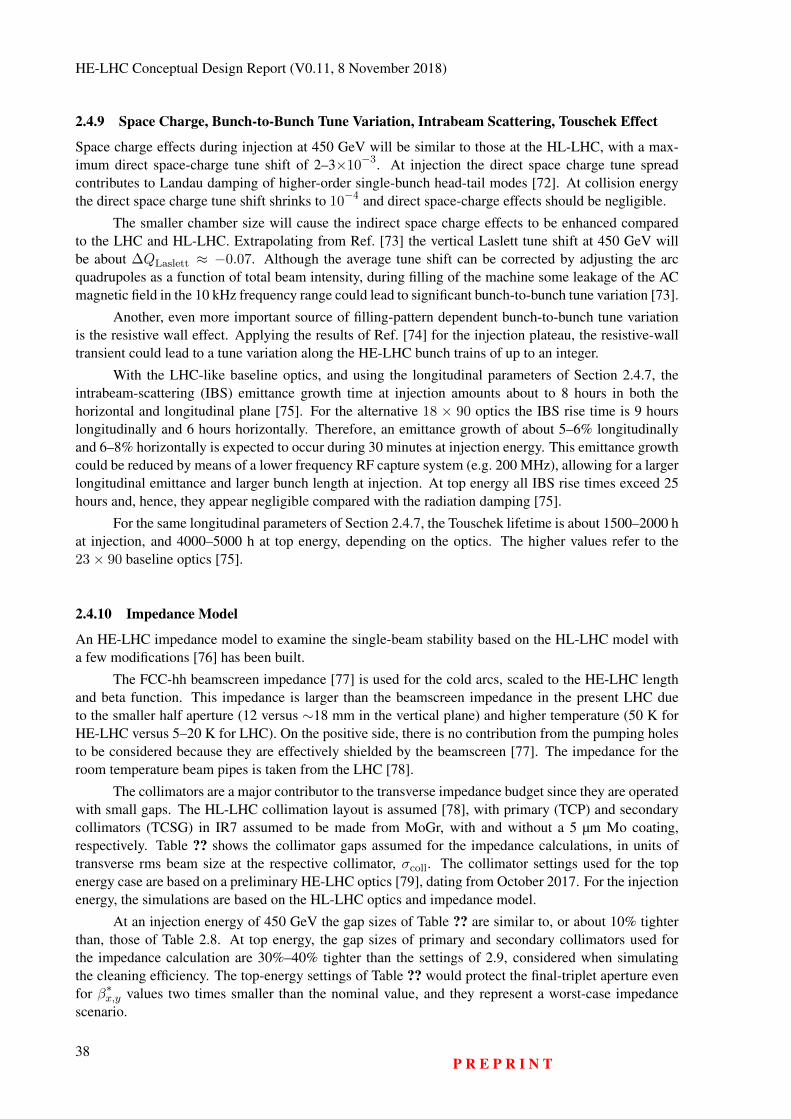
HE-LHC Conceptual Design Report (V0.11, 8 November 2018)
2.4.9 Space Charge, Bunch-to-Bunch Tune Variation, Intrabeam Scattering, Touschek Effect
Space charge effects during injection at 450 GeV will be similar to those at the HL-LHC, with a max-imum direct space-charge tune shift of 2–3×10⁻³. At injection the direct space charge tune spreadcontributes to Landau damping of higher-order single-bunch head-tail modes [72]. At collision energythe direct space charge tune shift shrinks to 10−4 and direct space-charge effects should be negligible.
The smaller chamber size will cause the indirect space charge effects to be enhanced comparedto the LHC and HL-LHC. Extrapolating from Ref. [73] the vertical Laslett tune shift at 450 GeV willbe about ∆QLaslett ≈ −0.07. Although the average tune shift can be corrected by adjusting the arcquadrupoles as a function of total beam intensity, during filling of the machine some leakage of the ACmagnetic field in the 10 kHz frequency range could lead to significant bunch-to-bunch tune variation [73].
Another, even more important source of filling-pattern dependent bunch-to-bunch tune variationis the resistive wall effect. Applying the results of Ref. [74] for the injection plateau, the resistive-walltransient could lead to a tune variation along the HE-LHC bunch trains of up to an integer.
With the LHC-like baseline optics, and using the longitudinal parameters of Section 2.4.7, theintrabeam-scattering (IBS) emittance growth time at injection amounts about to 8 hours in both thehorizontal and longitudinal plane [75]. For the alternative 18 × 90 optics the IBS rise time is 9 hourslongitudinally and 6 hours horizontally. Therefore, an emittance growth of about 5–6% longitudinallyand 6–8% horizontally is expected to occur during 30 minutes at injection energy. This emittance growthcould be reduced by means of a lower frequency RF capture system (e.g. 200 MHz), allowing for a largerlongitudinal emittance and larger bunch length at injection. At top energy all IBS rise times exceed 25hours and, hence, they appear negligible compared with the radiation damping [75].
For the same longitudinal parameters of Section 2.4.7, the Touschek lifetime is about 1500–2000 hat injection, and 4000–5000 h at top energy, depending on the optics. The higher values refer to the23× 90 baseline optics [75].
2.4.10 Impedance Model
An HE-LHC impedance model to examine the single-beam stability based on the HL-LHC model witha few modifications [76] has been built.
The FCC-hh beamscreen impedance [77] is used for the cold arcs, scaled to the HE-LHC lengthand beta function. This impedance is larger than the beamscreen impedance in the present LHC dueto the smaller half aperture (12 versus ∼18 mm in the vertical plane) and higher temperature (50 K forHE-LHC versus 5–20 K for LHC). On the positive side, there is no contribution from the pumping holesto be considered because they are effectively shielded by the beamscreen [77]. The impedance for theroom temperature beam pipes is taken from the LHC [78].
The collimators are a major contributor to the transverse impedance budget since they are operatedwith small gaps. The HL-LHC collimation layout is assumed [78], with primary (TCP) and secondarycollimators (TCSG) in IR7 assumed to be made from MoGr, with and without a 5 µm Mo coating,respectively. Table ?? shows the collimator gaps assumed for the impedance calculations, in units oftransverse rms beam size at the respective collimator, σcoll. The collimator settings used for the topenergy case are based on a preliminary HE-LHC optics [79], dating from October 2017. For the injectionenergy, the simulations are based on the HL-LHC optics and impedance model.
At an injection energy of 450 GeV the gap sizes of Table ?? are similar to, or about 10% tighterthan, those of Table 2.8. At top energy, the gap sizes of primary and secondary collimators used forthe impedance calculation are 30%–40% tighter than the settings of 2.9, considered when simulatingthe cleaning efficiency. The top-energy settings of Table ?? would protect the final-triplet aperture evenfor β∗x,y values two times smaller than the nominal value, and they represent a worst-case impedancescenario.
38P R E P R I N T
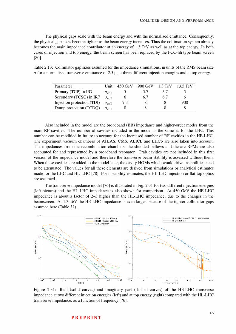
COLLIDER DESIGN AND PERFORMANCE
The physical gaps scale with the beam energy and with the normalised emittance. Consequently,the physical gap sizes become tighter as the beam energy increases. Thus the collimation system alreadybecomes the main impedance contributor at an energy of 1.3 TeV as well as at the top energy. In bothcases of injection and top energy, the beam screen has been replaced by the FCC-hh type beam screen[80].
Table 2.13: Collimator gap sizes assumed for the impedance simulations, in units of the RMS beam sizeσ for a normalised transverse emittance of 2.5 µ, at three different injection energies and at top energy.
Parameter Unit 450 GeV 900 GeV 1.3 TeV 13.5 TeVPrimary (TCP) in IR7 σcoll 5 5.7 5.7 5Secondary (TCSG) in IR7 σcoll 6 6.7 6.7 6Injection protection (TDI) σcoll 7.3 8 8 900Dump protection (TCDQ) σcoll 8 8 8 8
Also included in the model are the broadband (BB) impedance and higher-order modes from themain RF cavities. The number of cavities included in the model is the same as for the LHC. Thisnumber can be modified in future to account for the increased number of RF cavities in the HE-LHC.The experiment vacuum chambers of ATLAS, CMS, ALICE and LHCb are also taken into account.The impedances from the recombination chambers, the shielded bellows and the arc BPMs are alsoaccounted for and represented by a broadband resonator. Crab cavities are not included in this firstversion of the impedance model and therefore the transverse beam stability is assessed without them.When these cavities are added to the model later, the cavity HOMs which would drive instabilities needto be attenuated. The values for all these elements are derived from simulations or analytical estimatesmade for the LHC and HL-LHC [78]. For instability estimates, the HL-LHC injection or flat-top opticsare assumed.
The transverse impedance model [76] is illustrated in Fig. 2.31 for two different injection energies(left picture) and the HL-LHC impedance is also shown for comparison. At 450 GeV the HE-LHCimpedance is about a factor of 2–3 higher than the HL-LHC impedance, due to the changes in thebeamscreen. At 1.3 TeV the HE-LHC impedance is even larger because of the tighter collimator gapsassumed here (Table ??).
Figure 2.31: Real (solid curves) and imaginary part (dashed curves) of the HE-LHC transverseimpedance at two different injection energies (left) and at top energy (right) compared with the HL-LHCtransverse impedance, as a function of frequency [76].
P R E P R I N T39
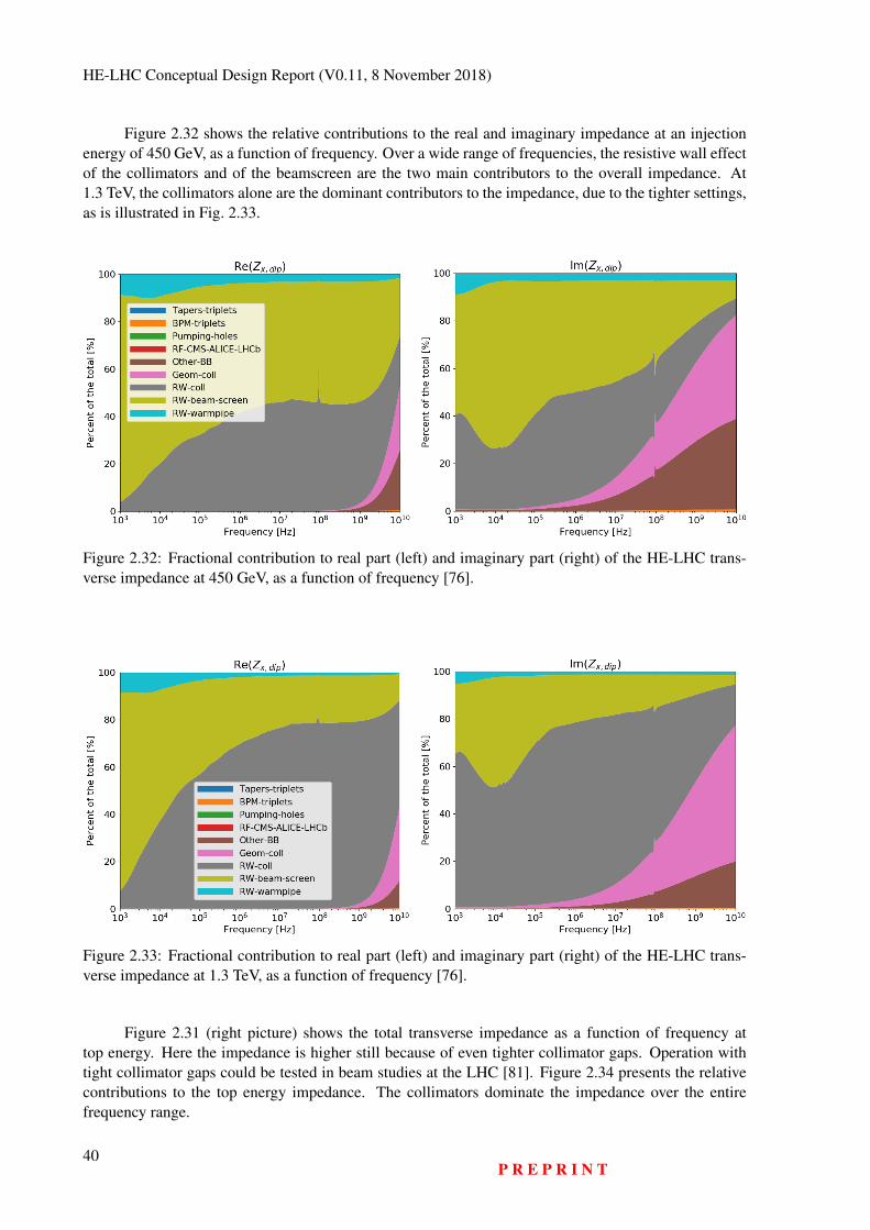
HE-LHC Conceptual Design Report (V0.11, 8 November 2018)
Figure 2.32 shows the relative contributions to the real and imaginary impedance at an injectionenergy of 450 GeV, as a function of frequency. Over a wide range of frequencies, the resistive wall effectof the collimators and of the beamscreen are the two main contributors to the overall impedance. At1.3 TeV, the collimators alone are the dominant contributors to the impedance, due to the tighter settings,as is illustrated in Fig. 2.33.
Figure 2.32: Fractional contribution to real part (left) and imaginary part (right) of the HE-LHC trans-verse impedance at 450 GeV, as a function of frequency [76].
Figure 2.33: Fractional contribution to real part (left) and imaginary part (right) of the HE-LHC trans-verse impedance at 1.3 TeV, as a function of frequency [76].
Figure 2.31 (right picture) shows the total transverse impedance as a function of frequency attop energy. Here the impedance is higher still because of even tighter collimator gaps. Operation withtight collimator gaps could be tested in beam studies at the LHC [81]. Figure 2.34 presents the relativecontributions to the top energy impedance. The collimators dominate the impedance over the entirefrequency range.
40P R E P R I N T
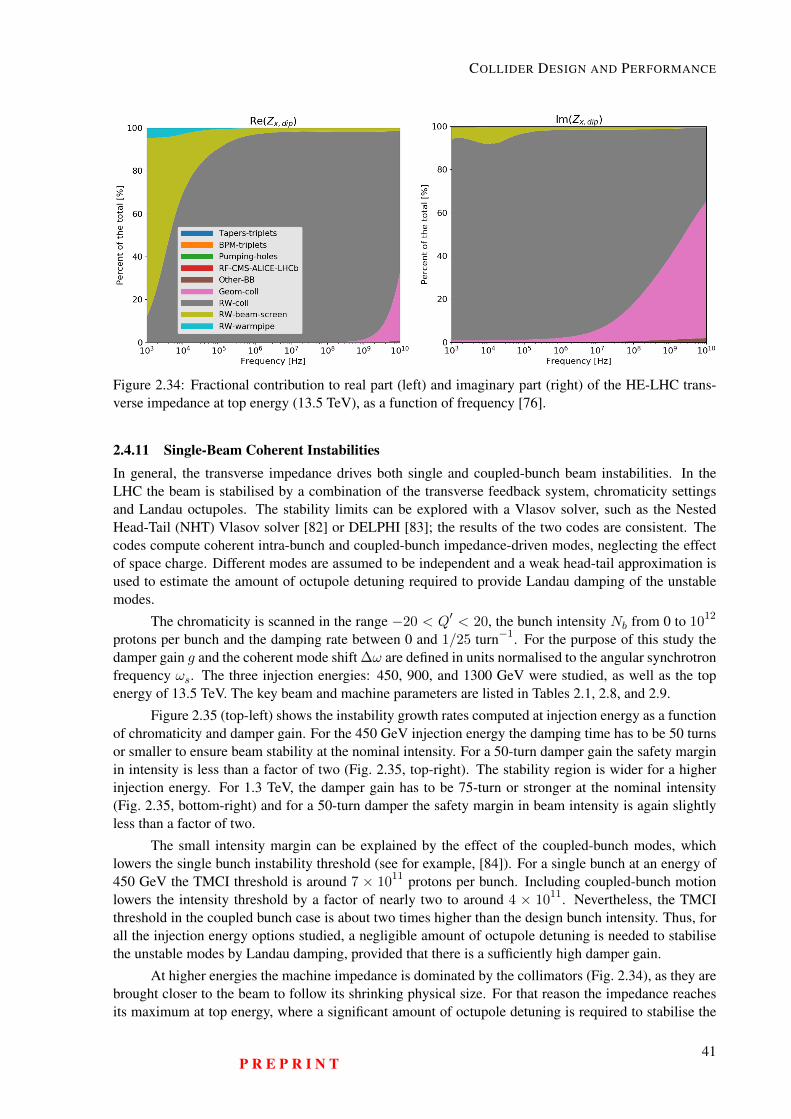
COLLIDER DESIGN AND PERFORMANCE
Figure 2.34: Fractional contribution to real part (left) and imaginary part (right) of the HE-LHC trans-verse impedance at top energy (13.5 TeV), as a function of frequency [76].
2.4.11 Single-Beam Coherent InstabilitiesIn general, the transverse impedance drives both single and coupled-bunch beam instabilities. In theLHC the beam is stabilised by a combination of the transverse feedback system, chromaticity settingsand Landau octupoles. The stability limits can be explored with a Vlasov solver, such as the NestedHead-Tail (NHT) Vlasov solver [82] or DELPHI [83]; the results of the two codes are consistent. Thecodes compute coherent intra-bunch and coupled-bunch impedance-driven modes, neglecting the effectof space charge. Different modes are assumed to be independent and a weak head-tail approximation isused to estimate the amount of octupole detuning required to provide Landau damping of the unstablemodes.
The chromaticity is scanned in the range −20 < Q′ < 20, the bunch intensity Nb from 0 to 1012
protons per bunch and the damping rate between 0 and 1/25 turn−1. For the purpose of this study thedamper gain g and the coherent mode shift ∆ω are defined in units normalised to the angular synchrotronfrequency ωs. The three injection energies: 450, 900, and 1300 GeV were studied, as well as the topenergy of 13.5 TeV. The key beam and machine parameters are listed in Tables 2.1, 2.8, and 2.9.
Figure 2.35 (top-left) shows the instability growth rates computed at injection energy as a functionof chromaticity and damper gain. For the 450 GeV injection energy the damping time has to be 50 turnsor smaller to ensure beam stability at the nominal intensity. For a 50-turn damper gain the safety marginin intensity is less than a factor of two (Fig. 2.35, top-right). The stability region is wider for a higherinjection energy. For 1.3 TeV, the damper gain has to be 75-turn or stronger at the nominal intensity(Fig. 2.35, bottom-right) and for a 50-turn damper the safety margin in beam intensity is again slightlyless than a factor of two.
The small intensity margin can be explained by the effect of the coupled-bunch modes, whichlowers the single bunch instability threshold (see for example, [84]). For a single bunch at an energy of450 GeV the TMCI threshold is around 7 × 10¹¹ protons per bunch. Including coupled-bunch motionlowers the intensity threshold by a factor of nearly two to around 4 × 10¹¹. Nevertheless, the TMCIthreshold in the coupled bunch case is about two times higher than the design bunch intensity. Thus, forall the injection energy options studied, a negligible amount of octupole detuning is needed to stabilisethe unstable modes by Landau damping, provided that there is a sufficiently high damper gain.
At higher energies the machine impedance is dominated by the collimators (Fig. 2.34), as they arebrought closer to the beam to follow its shrinking physical size. For that reason the impedance reachesits maximum at top energy, where a significant amount of octupole detuning is required to stabilise the
P R E P R I N T41
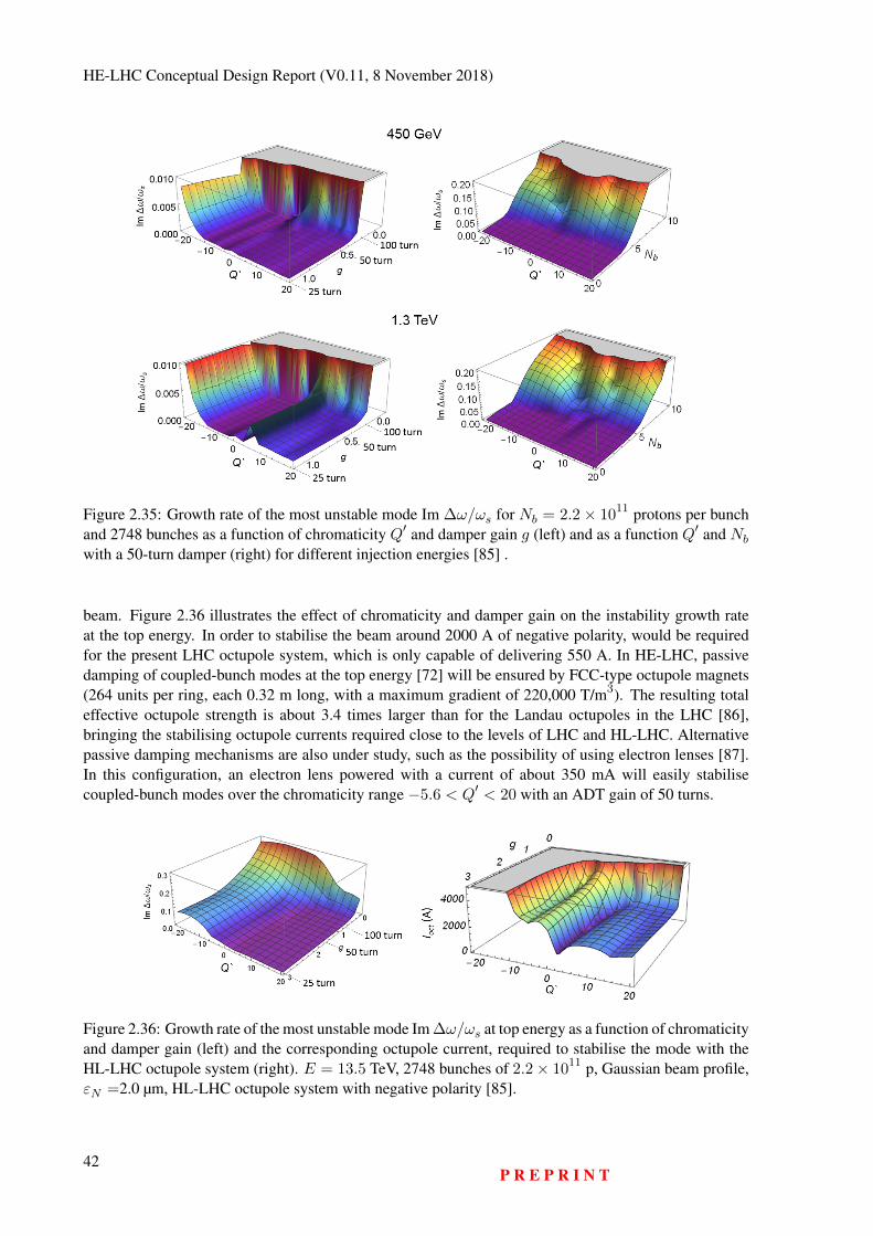
HE-LHC Conceptual Design Report (V0.11, 8 November 2018)
Figure 2.35: Growth rate of the most unstable mode Im ∆ω/ωs for Nb = 2.2× 10¹¹ protons per bunchand 2748 bunches as a function of chromaticity Q′ and damper gain g (left) and as a function Q′ and Nb
with a 50-turn damper (right) for different injection energies [85] .
beam. Figure 2.36 illustrates the effect of chromaticity and damper gain on the instability growth rateat the top energy. In order to stabilise the beam around 2000 A of negative polarity, would be requiredfor the present LHC octupole system, which is only capable of delivering 550 A. In HE-LHC, passivedamping of coupled-bunch modes at the top energy [72] will be ensured by FCC-type octupole magnets(264 units per ring, each 0.32 m long, with a maximum gradient of 220,000 T/m3). The resulting totaleffective octupole strength is about 3.4 times larger than for the Landau octupoles in the LHC [86],bringing the stabilising octupole currents required close to the levels of LHC and HL-LHC. Alternativepassive damping mechanisms are also under study, such as the possibility of using electron lenses [87].In this configuration, an electron lens powered with a current of about 350 mA will easily stabilisecoupled-bunch modes over the chromaticity range −5.6 < Q′ < 20 with an ADT gain of 50 turns.
Figure 2.36: Growth rate of the most unstable mode Im ∆ω/ωs at top energy as a function of chromaticityand damper gain (left) and the corresponding octupole current, required to stabilise the mode with theHL-LHC octupole system (right). E = 13.5 TeV, 2748 bunches of 2.2× 10¹¹ p, Gaussian beam profile,εN =2.0 µm, HL-LHC octupole system with negative polarity [85].
42P R E P R I N T
COLLIDER DESIGN AND PERFORMANCE
2.4.12 Electron CloudThe build-up of electron clouds may lead to coherent beam instabilities, through the interaction betweenthe beam and the electrons. The effect of two proposed beamscreen options on electron cloud build-upin the arc dipoles with a field of 16 T has been studied. The two beamscreen designs are:
– An LHC-type beamscreen with a saw-tooth structure in the synchrotron radiation impact area forreduced photon reflection [88] with half apertures scaled to 14 and 19 mm in the vertical andhorizontal planes respectively.
– The FCC-hh type beamscreen with ante-chambers for the synchrotron radiation and shielding ofthe pumping slots [89, 90].
Photoelectrons produced by the impact of synchrotron radiation can play an important role inseeding the cloud build-up [91]. Their effect could be even greater in the HE-LHC, where the numberof synchrotron photons produced would be nearly four times that of the present LHC and moreover, alarger fraction of the photons would have an energy above the work function of copper and could producephotoelectrons.
In the HE-LHC dipoles, where the magnetic field lines confine the electron cloud build-up tovertical stripes around the beam, it is mainly the photoelectrons produced at the top and bottom of thebeamscreen that can contribute to the build-up. The transverse distributions of absorbed photons in thearcs have been simulated with the SynRad3D code [92] for both beamscreen options [25]. The fractionof photons absorbed on the top and bottom of the beamscreen corresponds to less than one percent ofthe total number of absorbed photons for both beamscreen options. For the FCC-type beamscreen thefraction is roughly a factor of ten smaller than for the LHC-type beamscreen. The number of photoelec-trons depends on the photoemission yield of the absorbed photons and in the absence of an experimentalestimate of this yield, the number of absorbed photons can be used as an upper limit for the number ofphotoelectrons.
Electron cloud build-up simulations with photoelectron seeding were used to assess the effect ofthe beamscreen design. The resulting central electron densities as a function of the secondary electronyield (SEY) of the chamber surface are shown in Fig. 2.37. The threshold electron density for induc-ing single-bunch instabilities has been estimated from both analytical calculations [93] and from beamdynamics simulations to be around 1012 m−3 at flat top energy [94], assuming that the electron cloudis distributed over the entire ring. For typical SEY values, the simulated electron density lies below theinstability threshold for both chamber options. However, the FCC beamscreen has a lower density, as aresult of the lower photoelectron seeding. The heat load produced by the electron cloud, shown on theleft in Fig. 2.37, is lower for the FCC beamscreen.
Electron cloud build-up has been studied for the preferred beamscreen (FCC-type) in the main arcdipoles and in the arc quadrupoles, at both injection energy (in this case for an elevated energy of 1.3 TeV)and at flat-top energy with dipole and quadrupole fields of 16 T and 220 T/m, respectively. The actual arcquadrupole gradients at top energy are 336–352 T/m; the lower field gradient corresponds to a pessimisticscenario. In addition to the nominal beam parameters, two alternative beam options with lower pile-upwere considered: namely a beam with 12.5 ns bunch spacing, a bunch intensity of 1.1 × 10¹¹ protonsand normalised transverse emittance of 1.25 µm and a beam with 5 ns bunch spacing, bunch intensity0.5×1011 and normalised transverse emittance of 0.5 µm. The estimated central densities for these threebeam options at 1.3 TeV are displayed in Fig. 2.38. At injection, the beam is more prone to instabilities.For an injection energy of 450 GeV, the threshold electron density for single-bunch instability has beenestimated to be at about 1011 m−3 [94]. For a beam energy of 1.3 TeV, the threshold will only be slightlyhigher [94]. Taking into account that dipoles and quadrupoles cover around 80% and less than 10%of the machine circumference respectively, the nominal beam option could suffer from electron cloudinduced instabilities if the SEY of the surface is above 1.4. Suppressing the electron cloud build-up witha low-SEY surface treatment, such as an amorphous carbon coating or laser processing, would efficiently
P R E P R I N T43
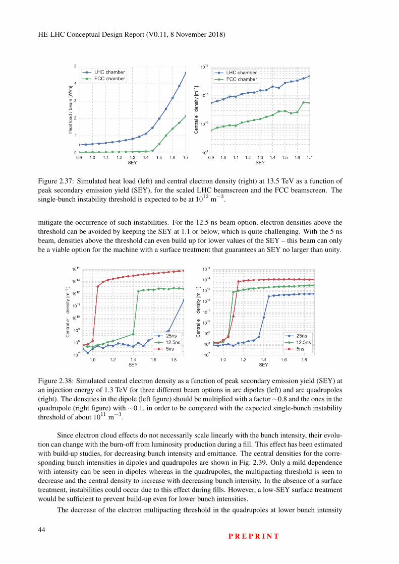
HE-LHC Conceptual Design Report (V0.11, 8 November 2018)
Figure 2.37: Simulated heat load (left) and central electron density (right) at 13.5 TeV as a function ofpeak secondary emission yield (SEY), for the scaled LHC beamscreen and the FCC beamscreen. Thesingle-bunch instability threshold is expected to be at 1012 m−3.
mitigate the occurrence of such instabilities. For the 12.5 ns beam option, electron densities above thethreshold can be avoided by keeping the SEY at 1.1 or below, which is quite challenging. With the 5 nsbeam, densities above the threshold can even build up for lower values of the SEY – this beam can onlybe a viable option for the machine with a surface treatment that guarantees an SEY no larger than unity.
Figure 2.38: Simulated central electron density as a function of peak secondary emission yield (SEY) atan injection energy of 1.3 TeV for three different beam options in arc dipoles (left) and arc quadrupoles(right). The densities in the dipole (left figure) should be multiplied with a factor∼0.8 and the ones in thequadrupole (right figure) with ∼0.1, in order to be compared with the expected single-bunch instabilitythreshold of about 1011 m−3.
Since electron cloud effects do not necessarily scale linearly with the bunch intensity, their evolu-tion can change with the burn-off from luminosity production during a fill. This effect has been estimatedwith build-up studies, for decreasing bunch intensity and emittance. The central densities for the corre-sponding bunch intensities in dipoles and quadrupoles are shown in Fig: 2.39. Only a mild dependencewith intensity can be seen in dipoles whereas in the quadrupoles, the multipacting threshold is seen todecrease and the central density to increase with decreasing bunch intensity. In the absence of a surfacetreatment, instabilities could occur due to this effect during fills. However, a low-SEY surface treatmentwould be sufficient to prevent build-up even for lower bunch intensities.
The decrease of the electron multipacting threshold in the quadrupoles at lower bunch intensity
44P R E P R I N T
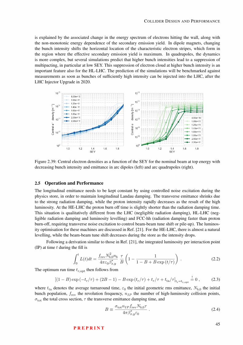
COLLIDER DESIGN AND PERFORMANCE
is explained by the associated change in the energy spectrum of electrons hitting the wall, along withthe non-monotonic energy dependence of the secondary emission yield. In dipole magnets, changingthe bunch intensity shifts the horizontal location of the characteristic electron stripes, which form inthe region where the effective secondary emission yield is maximum. In quadrupoles, the dynamicsis more complex, but several simulations predict that higher bunch intensities lead to a suppression ofmultipacting, in particular at low SEY. This suppression of electron cloud at higher bunch intensity is animportant feature also for the HL-LHC. The prediction of the simulations will be benchmarked againstmeasurements as soon as bunches of sufficiently high intensity can be injected into the LHC, after theLHC Injector Upgrade in 2020.
Figure 2.39: Central electron densities as a function of the SEY for the nominal beam at top energy withdecreasing bunch intensity and emittance in arc dipoles (left) and arc quadrupoles (right).
2.5 Operation and PerformanceThe longitudinal emittance needs to be kept constant by using controlled noise excitation during thephysics store, in order to maintain longitudinal Landau damping. The transverse emittance shrinks dueto the strong radiation damping, while the proton intensity rapidly decreases as the result of the highluminosity. At the HE-LHC the proton burn off time is slightly shorter than the radiation damping time.This situation is qualitatively different from the LHC (negligible radiation damping), HL-LHC (neg-ligible radiation damping and luminosity levelling) and FCC-hh (radiation damping faster than protonburn-off, requiring transverse noise excitation to control beam-beam tune shift or pile-up). The luminos-ity optimisation for these machines are discussed in Ref. [21]. For the HE-LHC, there is almost a naturallevelling, while the beam-beam tune shift decreases during the store as the intensity drops.
Following a derivation similar to those in Ref. [21], the integrated luminosity per interaction point(IP) at time t during the fill is∫ t
0L(t)dt =
frevN2b,0nb
4πε0β∗x,y
τ
B
(1− 1
1−B +B exp (t/τ)
). (2.2)
The optimum run time tr,opt then follows from
[(1−B) exp (−tr/τ) + (2B − 1)−B exp (tr/τ) + tr/τ + tta/τ ]tr=tr,opt
!= 0 , (2.3)
where tta denotes the average turnaround time, ε0 the initial geometric rms emittance, Nb,0 the initialbunch population, frev the revolution frequency, nIP the number of high-luminosity collision points,σtot the total cross section, τ the transverse emittance damping time, and
B ≡σtotnIP frevNb,0τ
4πβ∗x,yε0
. (2.4)
P R E P R I N T45
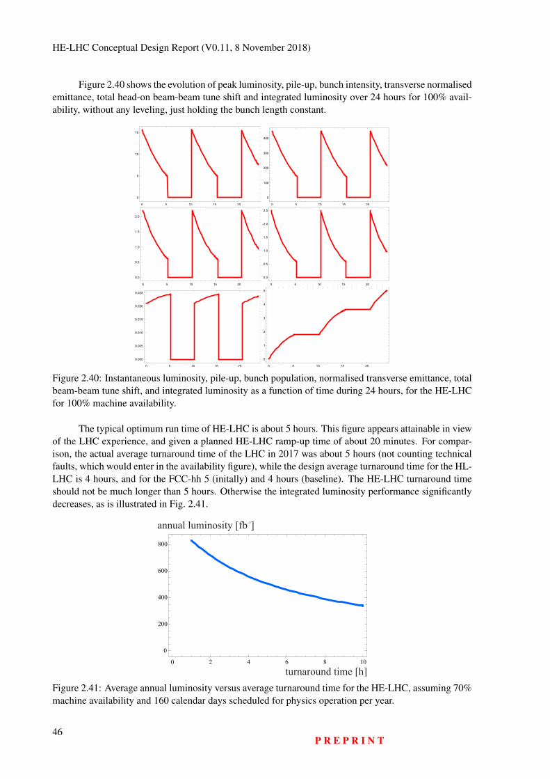
HE-LHC Conceptual Design Report (V0.11, 8 November 2018)
Figure 2.40 shows the evolution of peak luminosity, pile-up, bunch intensity, transverse normalisedemittance, total head-on beam-beam tune shift and integrated luminosity over 24 hours for 100% avail-ability, without any leveling, just holding the bunch length constant.
0 5 10 15 20
0
5
10
15
0 5 10 15 20
0
100
200
300
400
0 5 10 15 20
0.0
0.5
1.0
1.5
2.0
0 5 10 15 20
0.0
0.5
1.0
1.5
2.0
2.5
0 5 10 15 20
0.000
0.005
0.010
0.015
0.020
0.025
0 5 10 15 20
0
1
2
3
4
5
Figure 2.40: Instantaneous luminosity, pile-up, bunch population, normalised transverse emittance, totalbeam-beam tune shift, and integrated luminosity as a function of time during 24 hours, for the HE-LHCfor 100% machine availability.
The typical optimum run time of HE-LHC is about 5 hours. This figure appears attainable in viewof the LHC experience, and given a planned HE-LHC ramp-up time of about 20 minutes. For compar-ison, the actual average turnaround time of the LHC in 2017 was about 5 hours (not counting technicalfaults, which would enter in the availability figure), while the design average turnaround time for the HL-LHC is 4 hours, and for the FCC-hh 5 (initally) and 4 hours (baseline). The HE-LHC turnaround timeshould not be much longer than 5 hours. Otherwise the integrated luminosity performance significantlydecreases, as is illustrated in Fig. 2.41.
0 2 4 6 8 10
0
200
400
600
800
turnaround time [h]
annual luminosity [fb ]-1
Figure 2.41: Average annual luminosity versus average turnaround time for the HE-LHC, assuming 70%machine availability and 160 calendar days scheduled for physics operation per year.
46P R E P R I N T
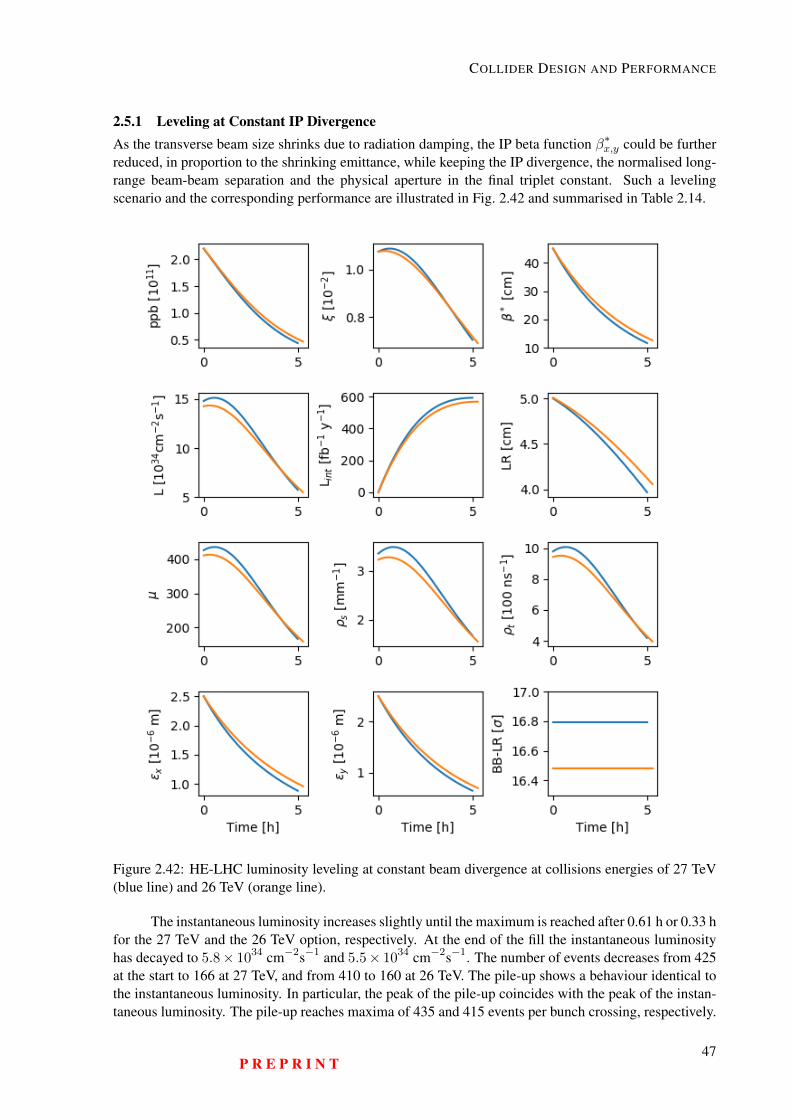
COLLIDER DESIGN AND PERFORMANCE
2.5.1 Leveling at Constant IP DivergenceAs the transverse beam size shrinks due to radiation damping, the IP beta function β∗x,y could be furtherreduced, in proportion to the shrinking emittance, while keeping the IP divergence, the normalised long-range beam-beam separation and the physical aperture in the final triplet constant. Such a levelingscenario and the corresponding performance are illustrated in Fig. 2.42 and summarised in Table 2.14.
Figure 2.42: HE-LHC luminosity leveling at constant beam divergence at collisions energies of 27 TeV(blue line) and 26 TeV (orange line).
The instantaneous luminosity increases slightly until the maximum is reached after 0.61 h or 0.33 hfor the 27 TeV and the 26 TeV option, respectively. At the end of the fill the instantaneous luminosityhas decayed to 5.8× 1034 cm−2s−1 and 5.5× 1034 cm−2s−1. The number of events decreases from 425at the start to 166 at 27 TeV, and from 410 to 160 at 26 TeV. The pile-up shows a behaviour identical tothe instantaneous luminosity. In particular, the peak of the pile-up coincides with the peak of the instan-taneous luminosity. The pile-up reaches maxima of 435 and 415 events per bunch crossing, respectively.
P R E P R I N T47
HE-LHC Conceptual Design Report (V0.11, 8 November 2018)
During operation at 27 TeV, about 3.35 collisions per mm and about 980 collisions per ns occur at thestart of the fill and the peak values of the pile-up densities are 3.48 collisions per mm and 1010 collisionsper ns. In the case of colliding at 26 TeV, 3.22 collisions per mm and 945 collisions per ns take placeinitially. At its maximum the pile-up densities reach 3.27 collisions per mm and 955 collisions per ns.
The value of β∗x,y is computed on every step to compensate for the decreased normalised emit-tance. Therefore, these two parameters show identical behaviour. The initial β∗ decreases from 45 cmto about 13 cm. The horizontal and vertical emittances decay from initial 2.5 µm in both planes to about1.0 µm horizontally and to about 0.7 µm vertically. Using an ATS scheme a minimum β∗ of about 15 cmseems feasible, which is about 2 cm greater than the minimum β∗ reached in these simulations. Improvedsimulations will be required in order to avoid falling below this limit. The number of intermediate opticssets required at 27 and 26 TeV collision energy is 160 and 155, respectively and accurate commissioningof over 100 optics may be a challenge. In the case of 27 TeV collision energy with a fill time of 4.99 h and160 different β∗ values, one can conclude that the optics needs to be changed every 2 minutes. Alterna-tively one could make larger steps and use each of the (remaining) fewer intermediate optics over a longerperiod of time. The beam-beam parameter does not increase significantly over the fill. It does not exceed1.1 × 10−2 per interaction point and is therefore in the order of the maximum acceptable beam-beamtune shift of 1.0× 10⁻² to 1.5× 10⁻² per interaction point [95–97].
The main benefit of this mode of operation is the possibility of harvesting a higher integratedluminosity while keeping a constant crossing angle and a constant long-range beam-beam separation inunits of σ. With respect to the baseline scenarios the integrated luminosity is increased by 25% for bothcollision energies.
2.6 Heavy Ion OperationIt is assumed that HE-LHC will use the same Pb beams as the HL-LHC, in terms of charge and nor-malised emittance. In the high luminosity-burnoff regime, the integrated luminosity per fill is given bythe ratio of the total number of Pb nuclei in one beam to the total cross-section, NPb/σtot. For only2 experiments taking luminosity (rather than 3 or 4 at HL-LHC), at roughly twice the energy, one canestimate that the Pb-Pb integrated luminosity per experiment would be about a factor of 2–3 better thanfor HL-LHC because of the higher energy, fast radiation damping and shorter fills. The expected inte-grated luminosity then amounts to around 10 nb−1 per one month run. The peak luminosity could bewell over 2 × 1028 cm−2 s−1, but would probably be levelled to something lower. For p–Pb collisions
Table 2.14: Initial (I) and final (F) performance parameters for constant IP divergence at 27 and 26 TeV.
Parameter Unit27 TeV 26 TeV
I F I FL 1034 cm−2s−1 15 5.8 14 5.5Lint fb−1y−1 − 590 − 570ppb 1011 2.2 0.44 2.2 0.46β∗ cm 45 12 45 13LR cm 5.0 4.0 5.0 4.1
BB-LR σ 16.795 16.795 16.485 16.485µ − 425 166 410 160%s mm−1 3.35 1.69 3.22 1.56%t 100 ns−1 980 420 945 395εx µm 2.5 0.9 2.5 1.0εy µm 2.5 0.6 2.5 0.7tfill h 4.99 5.27
48P R E P R I N T
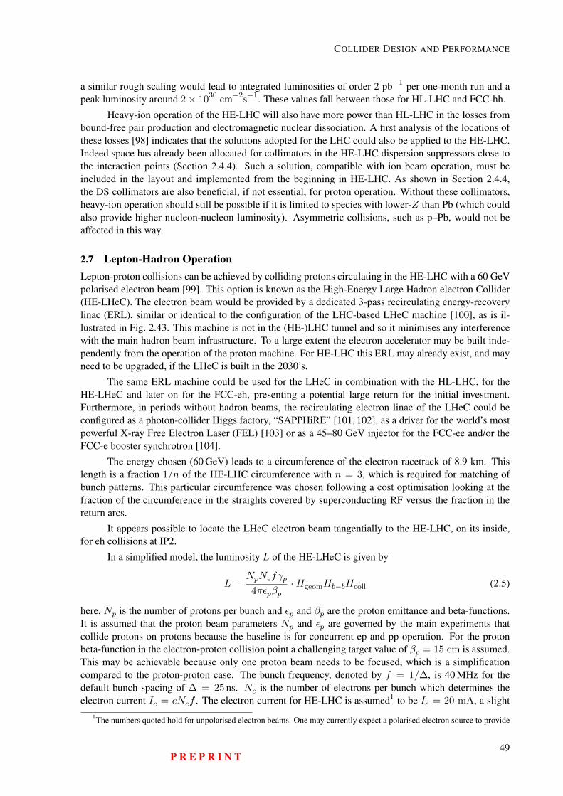
COLLIDER DESIGN AND PERFORMANCE
a similar rough scaling would lead to integrated luminosities of order 2 pb−1 per one-month run and apeak luminosity around 2× 1030 cm−2s−1. These values fall between those for HL-LHC and FCC-hh.
Heavy-ion operation of the HE-LHC will also have more power than HL-LHC in the losses frombound-free pair production and electromagnetic nuclear dissociation. A first analysis of the locations ofthese losses [98] indicates that the solutions adopted for the LHC could also be applied to the HE-LHC.Indeed space has already been allocated for collimators in the HE-LHC dispersion suppressors close tothe interaction points (Section 2.4.4). Such a solution, compatible with ion beam operation, must beincluded in the layout and implemented from the beginning in HE-LHC. As shown in Section 2.4.4,the DS collimators are also beneficial, if not essential, for proton operation. Without these collimators,heavy-ion operation should still be possible if it is limited to species with lower-Z than Pb (which couldalso provide higher nucleon-nucleon luminosity). Asymmetric collisions, such as p–Pb, would not beaffected in this way.
2.7 Lepton-Hadron OperationLepton-proton collisions can be achieved by colliding protons circulating in the HE-LHC with a 60 GeVpolarised electron beam [99]. This option is known as the High-Energy Large Hadron electron Collider(HE-LHeC). The electron beam would be provided by a dedicated 3-pass recirculating energy-recoverylinac (ERL), similar or identical to the configuration of the LHC-based LHeC machine [100], as is il-lustrated in Fig. 2.43. This machine is not in the (HE-)LHC tunnel and so it minimises any interferencewith the main hadron beam infrastructure. To a large extent the electron accelerator may be built inde-pendently from the operation of the proton machine. For HE-LHC this ERL may already exist, and mayneed to be upgraded, if the LHeC is built in the 2030’s.
The same ERL machine could be used for the LHeC in combination with the HL-LHC, for theHE-LHeC and later on for the FCC-eh, presenting a potential large return for the initial investment.Furthermore, in periods without hadron beams, the recirculating electron linac of the LHeC could beconfigured as a photon-collider Higgs factory, “SAPPHiRE” [101, 102], as a driver for the world’s mostpowerful X-ray Free Electron Laser (FEL) [103] or as a 45–80 GeV injector for the FCC-ee and/or theFCC-e booster synchrotron [104].
The energy chosen (60 GeV) leads to a circumference of the electron racetrack of 8.9 km. Thislength is a fraction 1/n of the HE-LHC circumference with n = 3, which is required for matching ofbunch patterns. This particular circumference was chosen following a cost optimisation looking at thefraction of the circumference in the straights covered by superconducting RF versus the fraction in thereturn arcs.
It appears possible to locate the LHeC electron beam tangentially to the HE-LHC, on its inside,for eh collisions at IP2.
In a simplified model, the luminosity L of the HE-LHeC is given by
L =NpNefγp4πεpβp
·HgeomHb−bHcoll (2.5)
here, Np is the number of protons per bunch and εp and βp are the proton emittance and beta-functions.It is assumed that the proton beam parameters Np and εp are governed by the main experiments thatcollide protons on protons because the baseline is for concurrent ep and pp operation. For the protonbeta-function in the electron-proton collision point a challenging target value of βp = 15 cm is assumed.This may be achievable because only one proton beam needs to be focused, which is a simplificationcompared to the proton-proton case. The bunch frequency, denoted by f = 1/∆, is 40 MHz for thedefault bunch spacing of ∆ = 25 ns. Ne is the number of electrons per bunch which determines theelectron current Ie = eNef . The electron current for HE-LHC is assumed1 to be Ie = 20 mA, a slight
1The numbers quoted hold for unpolarised electron beams. One may currently expect a polarised electron source to provide
P R E P R I N T49
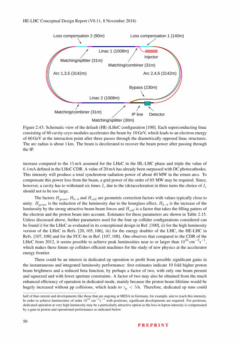
HE-LHC Conceptual Design Report (V0.11, 8 November 2018)
Injector
Arc 1,3,5 (3142m) Arc 2,4,6 (3142m)
Matching/splitter (30m)IP line Detector
Linac 1 (1008m)
Linac 2 (1008m)
Bypass (230m)
Loss compensation 1 (140m)Loss compensation 2 (90m)
Matching/splitter (31m)
Matching/combiner (31m)
Matching/combiner (31m)
Figure 2.43: Schematic view of the default (HE-)LHeC configuration [100]. Each superconducting linacconsisting of 60 cavity-cryo-modules accelerates the beam by 10 GeV, which leads to an electron energyof 60 GeV at the interaction point after three passes through the diametrically opposed linac structures.The arc radius is about 1 km. The beam is decelerated to recover the beam power after passing throughthe IP.
increase compared to the 15 mA assumed for the LHeC in the HL-LHC phase and triple the value of6.4 mA defined in the LHeC CDR. A value of 20 mA has already been surpassed with DC photocathodes.This intensity will produce a total synchrotron radiation power of about 40 MW in the return arcs. Tocompensate this power loss from the beam, a grid power of the order of 65 MW may be required. Since,however, a cavity has to withstand six times Ie due to the (de)acceleration in three turns the choice of Ieshould not to be too large.
The factors Hgeom, Hb−b and Hcoll are geometric correction factors with values typically close tounity. Hgeom is the reduction of the luminosity due to the hourglass effect, Hb−b is the increase of theluminosity by the strong attractive beam-beam forces and Hcoll is a factor that takes the filling patters ofthe electron and the proton beam into account. Estimates for these parameters are shown in Table 2.15.Unless discussed above, further parameters used for the four ep collider configurations considered canbe found i) for the LHeC as evaluated in its conceptional design in Ref. [100], ii) for the high luminosityversion of the LHeC in Refs. [20, 105, 106], iii) for the energy doubler of the LHC, the HE-LHC inRefs. [107, 108] and for the FCC-he in Ref. [107, 108]. One observes that compared to the CDR of theLHeC from 2012, it seems possible to achieve peak luminosities near to or larger than 1034 cm−2s−1,which makes these future ep colliders efficient machines for the study of new physics at the acceleratorenergy frontier.
There could be an interest in dedicated ep operation to profit from possible significant gains inthe instantaneous and integrated luminosity performance: first estimates indicate 10 fold higher protonbeam brightness and a reduced beta function, by perhaps a factor of two, with only one beam presentand squeezed and with fewer aperture constraints. A factor of two may also be obtained from the muchenhanced efficiency of operation in dedicated mode, mainly because the proton beam lifetime would behugely increased without pp collisions, which leads to τp < 5 h. Therefore, dedicated ep runs could
half of that current and developments like those that are ongoing at MESA in Germany, for example, aim to reach this intensity.In order to achieve luminosities of order 1033 cm−2s−1 with positrons, significant developments are required. For positrons,dedicated operation at very high luminosity may be a particularly attractive option as the loss in lepton intensity is compensatedby a gain in proton and operational performance as indicated below.
50P R E P R I N T
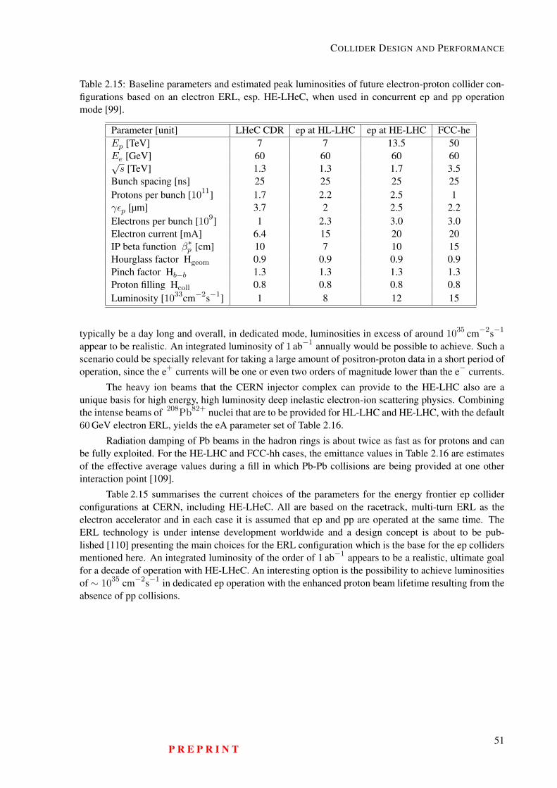
COLLIDER DESIGN AND PERFORMANCE
Table 2.15: Baseline parameters and estimated peak luminosities of future electron-proton collider con-figurations based on an electron ERL, esp. HE-LHeC, when used in concurrent ep and pp operationmode [99].
Parameter [unit] LHeC CDR ep at HL-LHC ep at HE-LHC FCC-heEp [TeV] 7 7 13.5 50Ee [GeV] 60 60 60 60√s [TeV] 1.3 1.3 1.7 3.5
Bunch spacing [ns] 25 25 25 25Protons per bunch [1011] 1.7 2.2 2.5 1γεp [µm] 3.7 2 2.5 2.2Electrons per bunch [109] 1 2.3 3.0 3.0Electron current [mA] 6.4 15 20 20IP beta function β∗p [cm] 10 7 10 15Hourglass factor Hgeom 0.9 0.9 0.9 0.9Pinch factor Hb−b 1.3 1.3 1.3 1.3Proton filling Hcoll 0.8 0.8 0.8 0.8Luminosity [1033cm−2s−1] 1 8 12 15
typically be a day long and overall, in dedicated mode, luminosities in excess of around 1035 cm−2s−1
appear to be realistic. An integrated luminosity of 1 ab−1 annually would be possible to achieve. Such ascenario could be specially relevant for taking a large amount of positron-proton data in a short period ofoperation, since the e+ currents will be one or even two orders of magnitude lower than the e− currents.
The heavy ion beams that the CERN injector complex can provide to the HE-LHC also are aunique basis for high energy, high luminosity deep inelastic electron-ion scattering physics. Combiningthe intense beams of 208Pb82+ nuclei that are to be provided for HL-LHC and HE-LHC, with the default60 GeV electron ERL, yields the eA parameter set of Table 2.16.
Radiation damping of Pb beams in the hadron rings is about twice as fast as for protons and canbe fully exploited. For the HE-LHC and FCC-hh cases, the emittance values in Table 2.16 are estimatesof the effective average values during a fill in which Pb-Pb collisions are being provided at one otherinteraction point [109].
Table 2.15 summarises the current choices of the parameters for the energy frontier ep colliderconfigurations at CERN, including HE-LHeC. All are based on the racetrack, multi-turn ERL as theelectron accelerator and in each case it is assumed that ep and pp are operated at the same time. TheERL technology is under intense development worldwide and a design concept is about to be pub-lished [110] presenting the main choices for the ERL configuration which is the base for the ep collidersmentioned here. An integrated luminosity of the order of 1 ab−1 appears to be a realistic, ultimate goalfor a decade of operation with HE-LHeC. An interesting option is the possibility to achieve luminositiesof ∼ 1035 cm−2s−1 in dedicated ep operation with the enhanced proton beam lifetime resulting from theabsence of pp collisions.
P R E P R I N T51
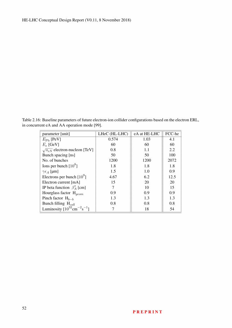
HE-LHC Conceptual Design Report (V0.11, 8 November 2018)
Table 2.16: Baseline parameters of future electron-ion collider configurations based on the electron ERL,in concurrent eA and AA operation mode [99].
parameter [unit] LHeC (HL-LHC) eA at HE-LHC FCC-heEPb [PeV] 0.574 1.03 4.1Ee [GeV] 60 60 60√seN electron-nucleon [TeV] 0.8 1.1 2.2
Bunch spacing [ns] 50 50 100No. of bunches 1200 1200 2072Ions per bunch [108] 1.8 1.8 1.8γεA [µm] 1.5 1.0 0.9Electrons per bunch [109] 4.67 6.2 12.5Electron current [mA] 15 20 20IP beta function β∗A [cm] 7 10 15Hourglass factor Hgeom 0.9 0.9 0.9Pinch factor Hb−b 1.3 1.3 1.3Bunch filling Hcoll 0.8 0.8 0.8Luminosity [1032cm−2s−1] 7 18 54
52P R E P R I N T
Chapter 3
Collider Technical Systems
3.1 OverviewMany of the LHC systems can be reproduced or reused for the HE-LHC. This chapter presents detailsof those technical systems which require particular attention and substantial R&D efforts: higher-fieldmagnets, suitably modified cryogenics, RF, beam transfer from a possibly new superconducting SPS,the beam-vacuum system adapted for much enhanced synchrotron radiation, magnet powering, beamdiagnostics, etc. The chapter also addresses the radiation environment in which the various systems willhave to perform.
3.2 Main Magnet System3.2.1 IntroductionThe magnetic system of the HE-LHC will profit a great deal from the experience gained with the LHC,which has demonstrated the feasibility and effectiveness of operating a large number of superconductingmagnets cooled by using superfluid helium at 1.9 K. The number of HE-LHC magnets will be about thesame as those of the LHC, but the field amplitude produced by the arc dipoles will be increased by almosta factor of two, whilst maintaining a similar beam aperture and twin configuration. The field increasewill be enabled by using Nb3Sn superconductor instead of the Nb-Ti used in the LHC arc dipoles. Withrespect to the conductor properties, the HE-LHC magnets will operate in a similar condition as the LHCmagnets, with 14% of margin on the load line and at about 60% of the maximum upper critical fieldBc20. It is believed that, with an appropriate R&D program, and if all magnets are cold tested beforeinstallation, this margin will be sufficient to achieve the nominal energy of the HE-LHC with limitedmagnet training. This technology, though not yet used in particle colliders, is being implemented fordipoles and quadrupoles of the HL-LHC project, where they will be operating at peak fields of between11 and 12 T. We estimate that this technology will be ready to start mass production of 16 T magnetswithin a decade from the manufacture of a first long model.
3.2.2 Superconducting Main DipoleThe main dipoles (MD) of the HE-LHC are twin-aperture magnets of cosine-theta layout assembledin a helium tight cold mass (CM) structure, integrated in a cryostat: a cross section of the system ispresented in Fig. 3.1 and a 3D of the assembly is shown in Fig. 3.2. Unlike for the FCC-hh, the CMfor the HE-LHC MD must be curved with a bending radius of about 2800 m, with a sagitta of 9 mm,or a deviation from a straight line of 3.5 cm over about 14 m. The HE-LHC MD CM has a total lengthbetween the two extremities of the beam pipe flanges of 15.46 m for the 23×90 optics (or 15.67 m forthe 18×90 optics), and a magnetic length of 13.73 m (13.94 m). Its external diameter is 800 mm. It is
53
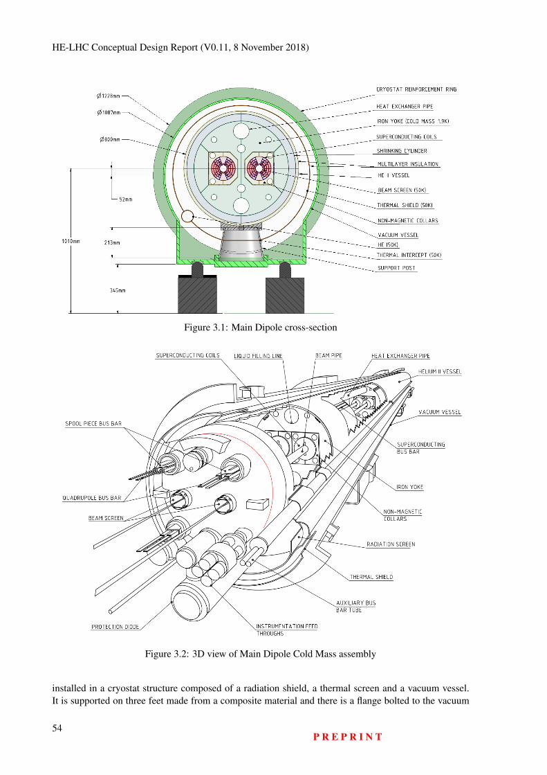
HE-LHC Conceptual Design Report (V0.11, 8 November 2018)
Figure 3.1: Main Dipole cross-section
Figure 3.2: 3D view of Main Dipole Cold Mass assembly
installed in a cryostat structure composed of a radiation shield, a thermal screen and a vacuum vessel.It is supported on three feet made from a composite material and there is a flange bolted to the vacuum
54P R E P R I N T
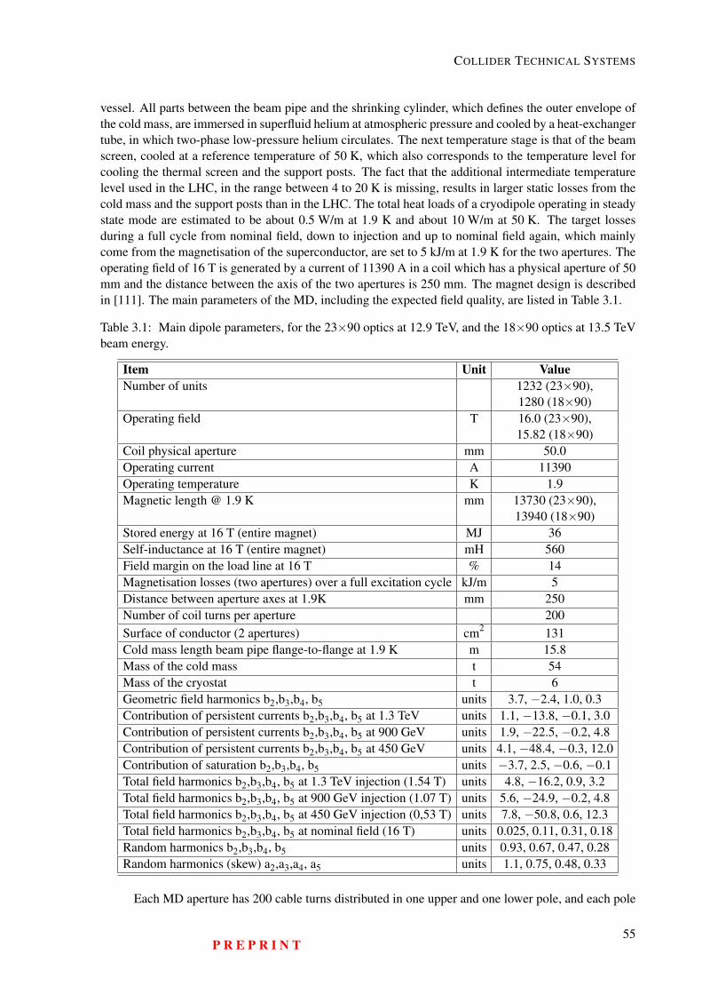
COLLIDER TECHNICAL SYSTEMS
vessel. All parts between the beam pipe and the shrinking cylinder, which defines the outer envelope ofthe cold mass, are immersed in superfluid helium at atmospheric pressure and cooled by a heat-exchangertube, in which two-phase low-pressure helium circulates. The next temperature stage is that of the beamscreen, cooled at a reference temperature of 50 K, which also corresponds to the temperature level forcooling the thermal screen and the support posts. The fact that the additional intermediate temperaturelevel used in the LHC, in the range between 4 to 20 K is missing, results in larger static losses from thecold mass and the support posts than in the LHC. The total heat loads of a cryodipole operating in steadystate mode are estimated to be about 0.5 W/m at 1.9 K and about 10 W/m at 50 K. The target lossesduring a full cycle from nominal field, down to injection and up to nominal field again, which mainlycome from the magnetisation of the superconductor, are set to 5 kJ/m at 1.9 K for the two apertures. Theoperating field of 16 T is generated by a current of 11390 A in a coil which has a physical aperture of 50mm and the distance between the axis of the two apertures is 250 mm. The magnet design is describedin [111]. The main parameters of the MD, including the expected field quality, are listed in Table 3.1.
Table 3.1: Main dipole parameters, for the 23×90 optics at 12.9 TeV, and the 18×90 optics at 13.5 TeVbeam energy.
Item Unit ValueNumber of units 1232 (23×90),
1280 (18×90)Operating field T 16.0 (23×90),
15.82 (18×90)Coil physical aperture mm 50.0Operating current A 11390Operating temperature K 1.9Magnetic length @ 1.9 K mm 13730 (23×90),
13940 (18×90)Stored energy at 16 T (entire magnet) MJ 36Self-inductance at 16 T (entire magnet) mH 560Field margin on the load line at 16 T % 14Magnetisation losses (two apertures) over a full excitation cycle kJ/m 5Distance between aperture axes at 1.9K mm 250Number of coil turns per aperture 200Surface of conductor (2 apertures) cm2 131Cold mass length beam pipe flange-to-flange at 1.9 K m 15.8Mass of the cold mass t 54Mass of the cryostat t 6Geometric field harmonics b2,b3,b4, b5 units 3.7, −2.4, 1.0, 0.3Contribution of persistent currents b2,b3,b4, b5 at 1.3 TeV units 1.1, −13.8, −0.1, 3.0Contribution of persistent currents b2,b3,b4, b5 at 900 GeV units 1.9, −22.5, −0.2, 4.8Contribution of persistent currents b2,b3,b4, b5 at 450 GeV units 4.1, −48.4, −0.3, 12.0Contribution of saturation b2,b3,b4, b5 units −3.7, 2.5, −0.6, −0.1Total field harmonics b2,b3,b4, b5 at 1.3 TeV injection (1.54 T) units 4.8, −16.2, 0.9, 3.2Total field harmonics b2,b3,b4, b5 at 900 GeV injection (1.07 T) units 5.6, −24.9, −0.2, 4.8Total field harmonics b2,b3,b4, b5 at 450 GeV injection (0,53 T) units 7.8, −50.8, 0.6, 12.3Total field harmonics b2,b3,b4, b5 at nominal field (16 T) units 0.025, 0.11, 0.31, 0.18Random harmonics b2,b3,b4, b5 units 0.93, 0.67, 0.47, 0.28Random harmonics (skew) a2,a3,a4, a5 units 1.1, 0.75, 0.48, 0.33
Each MD aperture has 200 cable turns distributed in one upper and one lower pole, and each pole
P R E P R I N T55
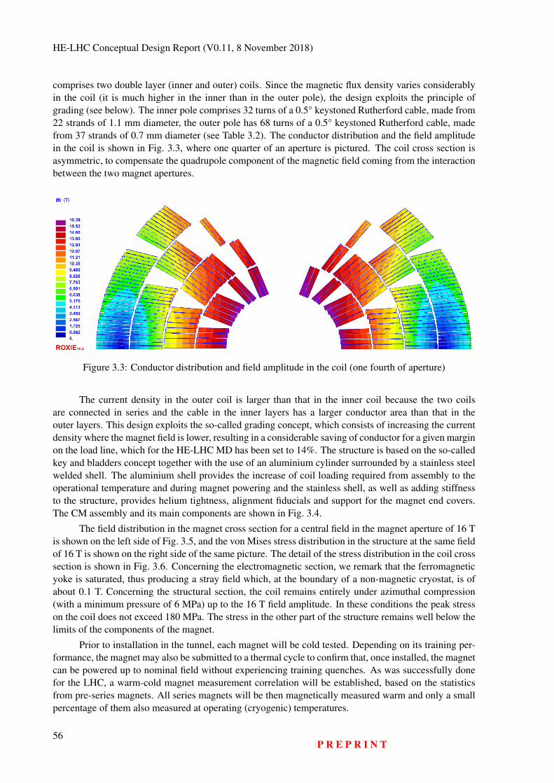
HE-LHC Conceptual Design Report (V0.11, 8 November 2018)
comprises two double layer (inner and outer) coils. Since the magnetic flux density varies considerablyin the coil (it is much higher in the inner than in the outer pole), the design exploits the principle ofgrading (see below). The inner pole comprises 32 turns of a 0.5° keystoned Rutherford cable, made from22 strands of 1.1 mm diameter, the outer pole has 68 turns of a 0.5° keystoned Rutherford cable, madefrom 37 strands of 0.7 mm diameter (see Table 3.2). The conductor distribution and the field amplitudein the coil is shown in Fig. 3.3, where one quarter of an aperture is pictured. The coil cross section isasymmetric, to compensate the quadrupole component of the magnetic field coming from the interactionbetween the two magnet apertures.
Figure 3.3: Conductor distribution and field amplitude in the coil (one fourth of aperture)
The current density in the outer coil is larger than that in the inner coil because the two coilsare connected in series and the cable in the inner layers has a larger conductor area than that in theouter layers. This design exploits the so-called grading concept, which consists of increasing the currentdensity where the magnet field is lower, resulting in a considerable saving of conductor for a given marginon the load line, which for the HE-LHC MD has been set to 14%. The structure is based on the so-calledkey and bladders concept together with the use of an aluminium cylinder surrounded by a stainless steelwelded shell. The aluminium shell provides the increase of coil loading required from assembly to theoperational temperature and during magnet powering and the stainless shell, as well as adding stiffnessto the structure, provides helium tightness, alignment fiducials and support for the magnet end covers.The CM assembly and its main components are shown in Fig. 3.4.
The field distribution in the magnet cross section for a central field in the magnet aperture of 16 Tis shown on the left side of Fig. 3.5, and the von Mises stress distribution in the structure at the same fieldof 16 T is shown on the right side of the same picture. The detail of the stress distribution in the coil crosssection is shown in Fig. 3.6. Concerning the electromagnetic section, we remark that the ferromagneticyoke is saturated, thus producing a stray field which, at the boundary of a non-magnetic cryostat, is ofabout 0.1 T. Concerning the structural section, the coil remains entirely under azimuthal compression(with a minimum pressure of 6 MPa) up to the 16 T field amplitude. In these conditions the peak stresson the coil does not exceed 180 MPa. The stress in the other part of the structure remains well below thelimits of the components of the magnet.
Prior to installation in the tunnel, each magnet will be cold tested. Depending on its training per-formance, the magnet may also be submitted to a thermal cycle to confirm that, once installed, the magnetcan be powered up to nominal field without experiencing training quenches. As was successfully donefor the LHC, a warm-cold magnet measurement correlation will be established, based on the statisticsfrom pre-series magnets. All series magnets will be then magnetically measured warm and only a smallpercentage of them also measured at operating (cryogenic) temperatures.
56P R E P R I N T
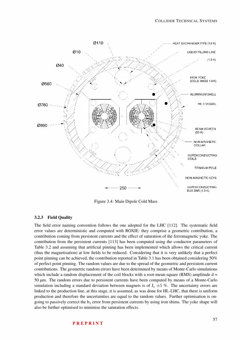
COLLIDER TECHNICAL SYSTEMS
Figure 3.4: Main Dipole Cold Mass
3.2.3 Field Quality
The field error naming convention follows the one adopted for the LHC [112]. The systematic fielderror values are deterministic and computed with ROXIE: they comprise a geometric contribution, acontribution coming from persistent currents and the effect of saturation of the ferromagnetic yoke. Thecontribution from the persistent currents [113] has been computed using the conductor parameters ofTable 3.2 and assuming that artificial pinning has been implemented which allows the critical current(thus the magnetisation) at low fields to be reduced. Considering that it is very unlikely that a perfectpoint pinning can be achieved, the contribution reported in Table 3.1 has been obtained considering 50%of perfect point pinning. The random values are due to the spread of the geometric and persistent currentcontributions. The geometric random errors have been determined by means of Monte-Carlo simulationswhich include a random displacement of the coil blocks with a root-mean-square (RMS) amplitude d =50 µm. The random errors due to persistent currents have been computed by means of a Monte-Carlosimulation including a standard deviation between magnets is of Jc ±5 %. The uncertainty errors arelinked to the production line, at this stage, it is assumed, as was done for HL-LHC, that there is uniformproduction and therefore the uncertainties are equal to the random values. Further optimisation is on-going to passively correct the b3 error from persistent currents by using iron shims. The yoke shape willalso be further optimised to minimise the saturation effects.
P R E P R I N T57
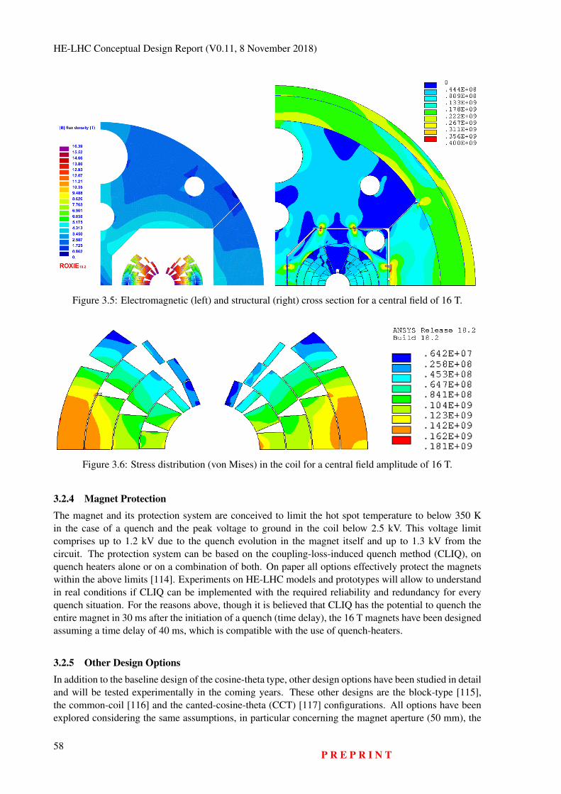
HE-LHC Conceptual Design Report (V0.11, 8 November 2018)
Figure 3.5: Electromagnetic (left) and structural (right) cross section for a central field of 16 T.
Figure 3.6: Stress distribution (von Mises) in the coil for a central field amplitude of 16 T.
3.2.4 Magnet ProtectionThe magnet and its protection system are conceived to limit the hot spot temperature to below 350 Kin the case of a quench and the peak voltage to ground in the coil below 2.5 kV. This voltage limitcomprises up to 1.2 kV due to the quench evolution in the magnet itself and up to 1.3 kV from thecircuit. The protection system can be based on the coupling-loss-induced quench method (CLIQ), onquench heaters alone or on a combination of both. On paper all options effectively protect the magnetswithin the above limits [114]. Experiments on HE-LHC models and prototypes will allow to understandin real conditions if CLIQ can be implemented with the required reliability and redundancy for everyquench situation. For the reasons above, though it is believed that CLIQ has the potential to quench theentire magnet in 30 ms after the initiation of a quench (time delay), the 16 T magnets have been designedassuming a time delay of 40 ms, which is compatible with the use of quench-heaters.
3.2.5 Other Design OptionsIn addition to the baseline design of the cosine-theta type, other design options have been studied in detailand will be tested experimentally in the coming years. These other designs are the block-type [115],the common-coil [116] and the canted-cosine-theta (CCT) [117] configurations. All options have beenexplored considering the same assumptions, in particular concerning the magnet aperture (50 mm), the
58P R E P R I N T
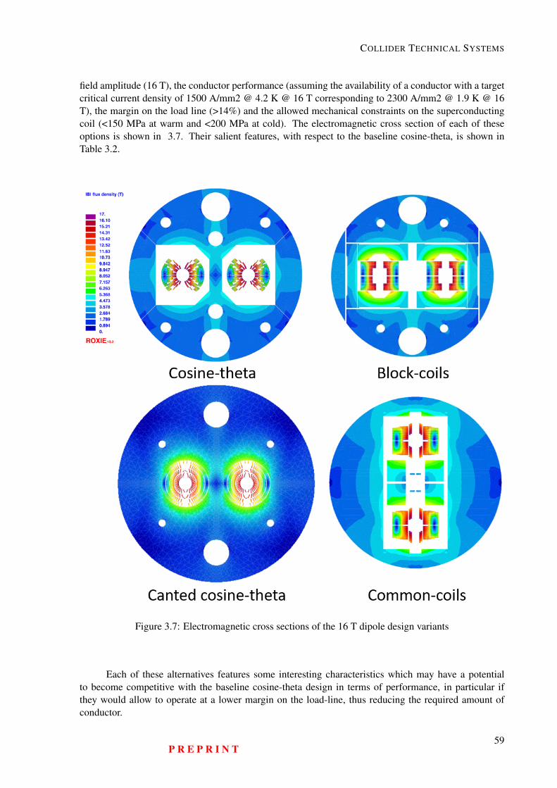
COLLIDER TECHNICAL SYSTEMS
field amplitude (16 T), the conductor performance (assuming the availability of a conductor with a targetcritical current density of 1500 A/mm2 @ 4.2 K @ 16 T corresponding to 2300 A/mm2 @ 1.9 K @ 16T), the margin on the load line (>14%) and the allowed mechanical constraints on the superconductingcoil (<150 MPa at warm and <200 MPa at cold). The electromagnetic cross section of each of theseoptions is shown in 3.7. Their salient features, with respect to the baseline cosine-theta, is shown inTable 3.2.
Figure 3.7: Electromagnetic cross sections of the 16 T dipole design variants
Each of these alternatives features some interesting characteristics which may have a potentialto become competitive with the baseline cosine-theta design in terms of performance, in particular ifthey would allow to operate at a lower margin on the load-line, thus reducing the required amount ofconductor.
P R E P R I N T59
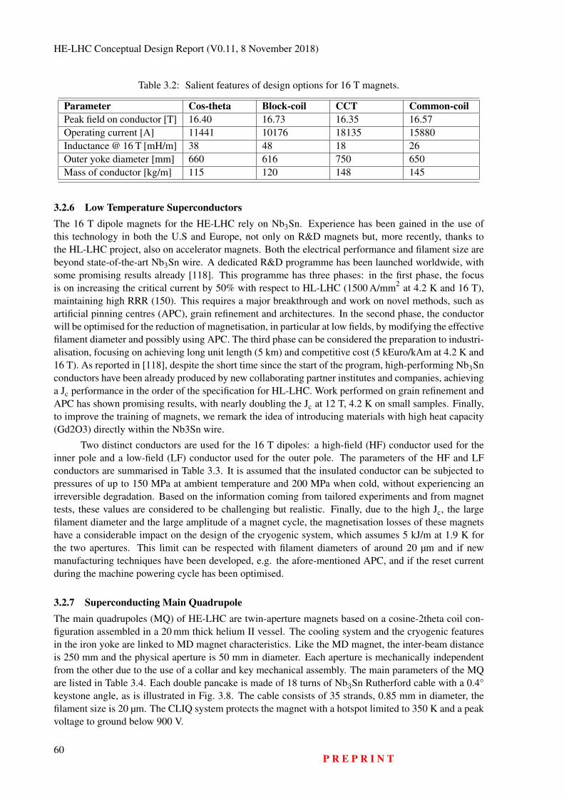
HE-LHC Conceptual Design Report (V0.11, 8 November 2018)
Table 3.2: Salient features of design options for 16 T magnets.
Parameter Cos-theta Block-coil CCT Common-coilPeak field on conductor [T] 16.40 16.73 16.35 16.57Operating current [A] 11441 10176 18135 15880Inductance @ 16 T [mH/m] 38 48 18 26Outer yoke diameter [mm] 660 616 750 650Mass of conductor [kg/m] 115 120 148 145
3.2.6 Low Temperature SuperconductorsThe 16 T dipole magnets for the HE-LHC rely on Nb3Sn. Experience has been gained in the use ofthis technology in both the U.S and Europe, not only on R&D magnets but, more recently, thanks tothe HL-LHC project, also on accelerator magnets. Both the electrical performance and filament size arebeyond state-of-the-art Nb3Sn wire. A dedicated R&D programme has been launched worldwide, withsome promising results already [118]. This programme has three phases: in the first phase, the focusis on increasing the critical current by 50% with respect to HL-LHC (1500 A/mm2 at 4.2 K and 16 T),maintaining high RRR (150). This requires a major breakthrough and work on novel methods, such asartificial pinning centres (APC), grain refinement and architectures. In the second phase, the conductorwill be optimised for the reduction of magnetisation, in particular at low fields, by modifying the effectivefilament diameter and possibly using APC. The third phase can be considered the preparation to industri-alisation, focusing on achieving long unit length (5 km) and competitive cost (5 kEuro/kAm at 4.2 K and16 T). As reported in [118], despite the short time since the start of the program, high-performing Nb3Snconductors have been already produced by new collaborating partner institutes and companies, achievinga Jc performance in the order of the specification for HL-LHC. Work performed on grain refinement andAPC has shown promising results, with nearly doubling the Jc at 12 T, 4.2 K on small samples. Finally,to improve the training of magnets, we remark the idea of introducing materials with high heat capacity(Gd2O3) directly within the Nb3Sn wire.
Two distinct conductors are used for the 16 T dipoles: a high-field (HF) conductor used for theinner pole and a low-field (LF) conductor used for the outer pole. The parameters of the HF and LFconductors are summarised in Table 3.3. It is assumed that the insulated conductor can be subjected topressures of up to 150 MPa at ambient temperature and 200 MPa when cold, without experiencing anirreversible degradation. Based on the information coming from tailored experiments and from magnettests, these values are considered to be challenging but realistic. Finally, due to the high Jc, the largefilament diameter and the large amplitude of a magnet cycle, the magnetisation losses of these magnetshave a considerable impact on the design of the cryogenic system, which assumes 5 kJ/m at 1.9 K forthe two apertures. This limit can be respected with filament diameters of around 20 µm and if newmanufacturing techniques have been developed, e.g. the afore-mentioned APC, and if the reset currentduring the machine powering cycle has been optimised.
3.2.7 Superconducting Main QuadrupoleThe main quadrupoles (MQ) of HE-LHC are twin-aperture magnets based on a cosine-2theta coil con-figuration assembled in a 20 mm thick helium II vessel. The cooling system and the cryogenic featuresin the iron yoke are linked to MD magnet characteristics. Like the MD magnet, the inter-beam distanceis 250 mm and the physical aperture is 50 mm in diameter. Each aperture is mechanically independentfrom the other due to the use of a collar and key mechanical assembly. The main parameters of the MQare listed in Table 3.4. Each double pancake is made of 18 turns of Nb3Sn Rutherford cable with a 0.4°keystone angle, as is illustrated in Fig. 3.8. The cable consists of 35 strands, 0.85 mm in diameter, thefilament size is 20 µm. The CLIQ system protects the magnet with a hotspot limited to 350 K and a peakvoltage to ground below 900 V.
60P R E P R I N T
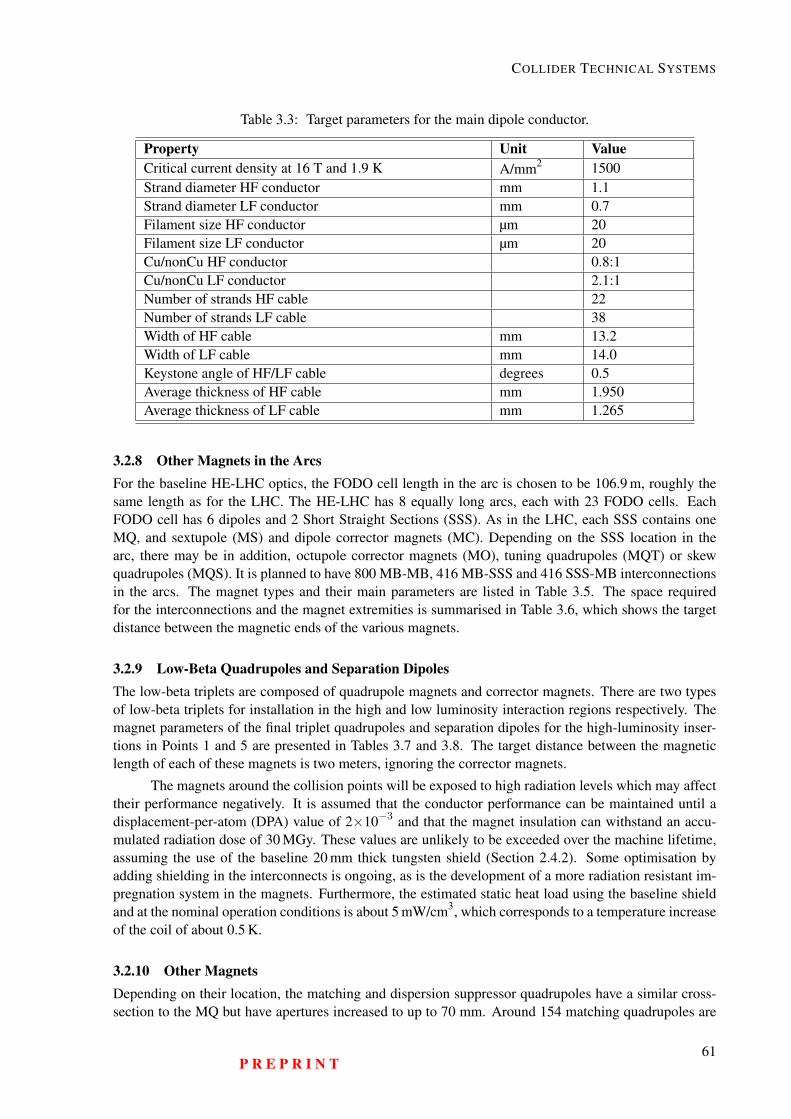
COLLIDER TECHNICAL SYSTEMS
Table 3.3: Target parameters for the main dipole conductor.
Property Unit ValueCritical current density at 16 T and 1.9 K A/mm2 1500Strand diameter HF conductor mm 1.1Strand diameter LF conductor mm 0.7Filament size HF conductor µm 20Filament size LF conductor µm 20Cu/nonCu HF conductor 0.8:1Cu/nonCu LF conductor 2.1:1Number of strands HF cable 22Number of strands LF cable 38Width of HF cable mm 13.2Width of LF cable mm 14.0Keystone angle of HF/LF cable degrees 0.5Average thickness of HF cable mm 1.950Average thickness of LF cable mm 1.265
3.2.8 Other Magnets in the ArcsFor the baseline HE-LHC optics, the FODO cell length in the arc is chosen to be 106.9 m, roughly thesame length as for the LHC. The HE-LHC has 8 equally long arcs, each with 23 FODO cells. EachFODO cell has 6 dipoles and 2 Short Straight Sections (SSS). As in the LHC, each SSS contains oneMQ, and sextupole (MS) and dipole corrector magnets (MC). Depending on the SSS location in thearc, there may be in addition, octupole corrector magnets (MO), tuning quadrupoles (MQT) or skewquadrupoles (MQS). It is planned to have 800 MB-MB, 416 MB-SSS and 416 SSS-MB interconnectionsin the arcs. The magnet types and their main parameters are listed in Table 3.5. The space requiredfor the interconnections and the magnet extremities is summarised in Table 3.6, which shows the targetdistance between the magnetic ends of the various magnets.
3.2.9 Low-Beta Quadrupoles and Separation DipolesThe low-beta triplets are composed of quadrupole magnets and corrector magnets. There are two typesof low-beta triplets for installation in the high and low luminosity interaction regions respectively. Themagnet parameters of the final triplet quadrupoles and separation dipoles for the high-luminosity inser-tions in Points 1 and 5 are presented in Tables 3.7 and 3.8. The target distance between the magneticlength of each of these magnets is two meters, ignoring the corrector magnets.
The magnets around the collision points will be exposed to high radiation levels which may affecttheir performance negatively. It is assumed that the conductor performance can be maintained until adisplacement-per-atom (DPA) value of 2×10⁻³ and that the magnet insulation can withstand an accu-mulated radiation dose of 30 MGy. These values are unlikely to be exceeded over the machine lifetime,assuming the use of the baseline 20 mm thick tungsten shield (Section 2.4.2). Some optimisation byadding shielding in the interconnects is ongoing, as is the development of a more radiation resistant im-pregnation system in the magnets. Furthermore, the estimated static heat load using the baseline shieldand at the nominal operation conditions is about 5 mW/cm3, which corresponds to a temperature increaseof the coil of about 0.5 K.
3.2.10 Other MagnetsDepending on their location, the matching and dispersion suppressor quadrupoles have a similar cross-section to the MQ but have apertures increased to up to 70 mm. Around 154 matching quadrupoles are
P R E P R I N T61
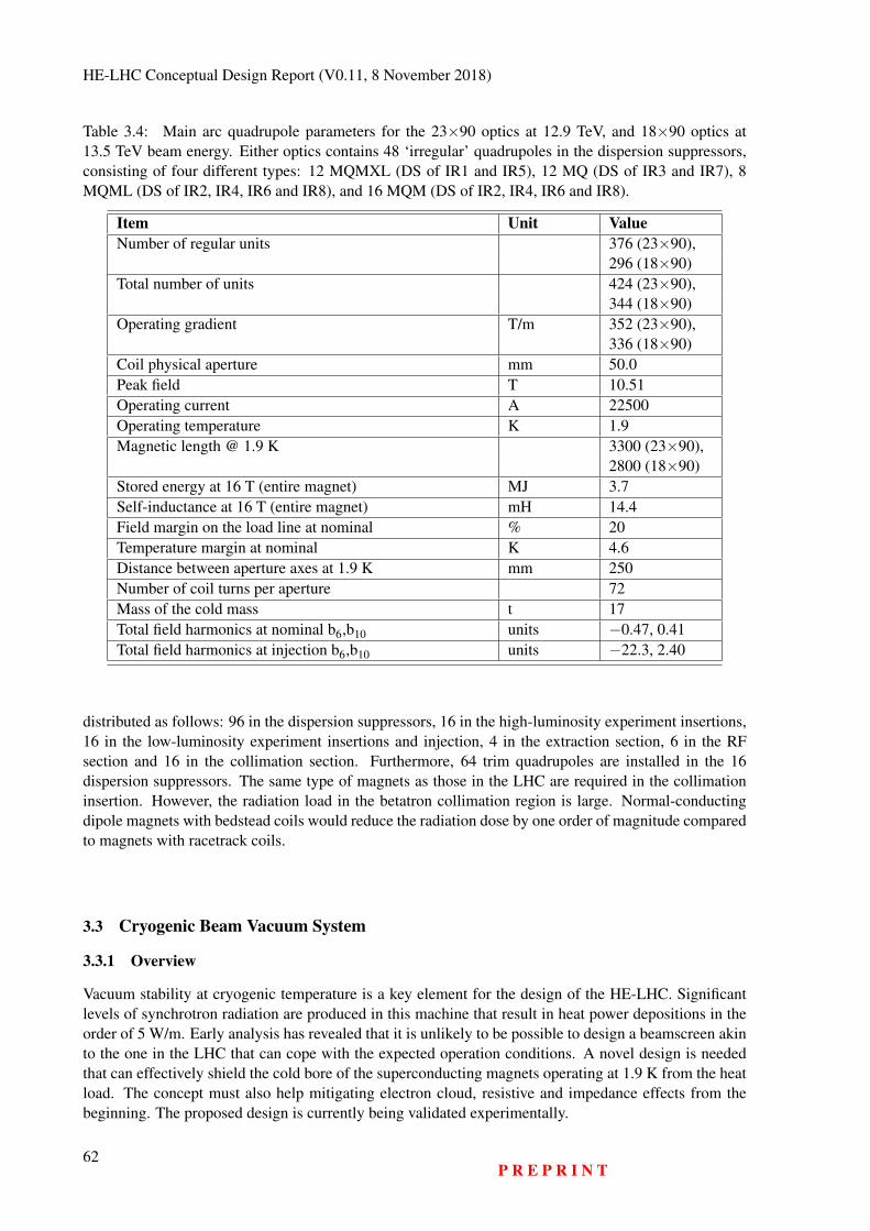
HE-LHC Conceptual Design Report (V0.11, 8 November 2018)
Table 3.4: Main arc quadrupole parameters for the 23×90 optics at 12.9 TeV, and 18×90 optics at13.5 TeV beam energy. Either optics contains 48 ‘irregular’ quadrupoles in the dispersion suppressors,consisting of four different types: 12 MQMXL (DS of IR1 and IR5), 12 MQ (DS of IR3 and IR7), 8MQML (DS of IR2, IR4, IR6 and IR8), and 16 MQM (DS of IR2, IR4, IR6 and IR8).
Item Unit ValueNumber of regular units 376 (23×90),
296 (18×90)Total number of units 424 (23×90),
344 (18×90)Operating gradient T/m 352 (23×90),
336 (18×90)Coil physical aperture mm 50.0Peak field T 10.51Operating current A 22500Operating temperature K 1.9Magnetic length @ 1.9 K 3300 (23×90),
2800 (18×90)Stored energy at 16 T (entire magnet) MJ 3.7Self-inductance at 16 T (entire magnet) mH 14.4Field margin on the load line at nominal % 20Temperature margin at nominal K 4.6Distance between aperture axes at 1.9 K mm 250Number of coil turns per aperture 72Mass of the cold mass t 17Total field harmonics at nominal b6,b10 units −0.47, 0.41Total field harmonics at injection b6,b10 units −22.3, 2.40
distributed as follows: 96 in the dispersion suppressors, 16 in the high-luminosity experiment insertions,16 in the low-luminosity experiment insertions and injection, 4 in the extraction section, 6 in the RFsection and 16 in the collimation section. Furthermore, 64 trim quadrupoles are installed in the 16dispersion suppressors. The same type of magnets as those in the LHC are required in the collimationinsertion. However, the radiation load in the betatron collimation region is large. Normal-conductingdipole magnets with bedstead coils would reduce the radiation dose by one order of magnitude comparedto magnets with racetrack coils.
3.3 Cryogenic Beam Vacuum System
3.3.1 Overview
Vacuum stability at cryogenic temperature is a key element for the design of the HE-LHC. Significantlevels of synchrotron radiation are produced in this machine that result in heat power depositions in theorder of 5 W/m. Early analysis has revealed that it is unlikely to be possible to design a beamscreen akinto the one in the LHC that can cope with the expected operation conditions. A novel design is neededthat can effectively shield the cold bore of the superconducting magnets operating at 1.9 K from the heatload. The concept must also help mitigating electron cloud, resistive and impedance effects from thebeginning. The proposed design is currently being validated experimentally.
62P R E P R I N T
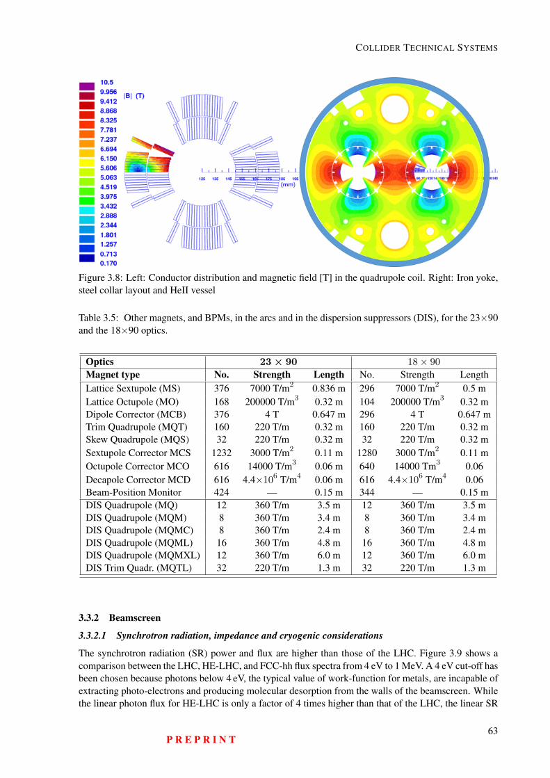
COLLIDER TECHNICAL SYSTEMS
Figure 3.8: Left: Conductor distribution and magnetic field [T] in the quadrupole coil. Right: Iron yoke,steel collar layout and HeII vessel
Table 3.5: Other magnets, and BPMs, in the arcs and in the dispersion suppressors (DIS), for the 23×90and the 18×90 optics.
Optics 23× 90 18× 90
Magnet type No. Strength Length No. Strength LengthLattice Sextupole (MS) 376 7000 T/m2 0.836 m 296 7000 T/m2 0.5 mLattice Octupole (MO) 168 200000 T/m3 0.32 m 104 200000 T/m3 0.32 mDipole Corrector (MCB) 376 4 T 0.647 m 296 4 T 0.647 mTrim Quadrupole (MQT) 160 220 T/m 0.32 m 160 220 T/m 0.32 mSkew Quadrupole (MQS) 32 220 T/m 0.32 m 32 220 T/m 0.32 mSextupole Corrector MCS 1232 3000 T/m2 0.11 m 1280 3000 T/m2 0.11 mOctupole Corrector MCO 616 14000 T/m3 0.06 m 640 14000 Tm3 0.06Decapole Corrector MCD 616 4.4×10⁶ T/m4 0.06 m 616 4.4×10⁶ T/m4 0.06Beam-Position Monitor 424 — 0.15 m 344 — 0.15 mDIS Quadrupole (MQ) 12 360 T/m 3.5 m 12 360 T/m 3.5 mDIS Quadrupole (MQM) 8 360 T/m 3.4 m 8 360 T/m 3.4 mDIS Quadrupole (MQMC) 8 360 T/m 2.4 m 8 360 T/m 2.4 mDIS Quadrupole (MQML) 16 360 T/m 4.8 m 16 360 T/m 4.8 mDIS Quadrupole (MQMXL) 12 360 T/m 6.0 m 12 360 T/m 6.0 mDIS Trim Quadr. (MQTL) 32 220 T/m 1.3 m 32 220 T/m 1.3 m
3.3.2 Beamscreen
3.3.2.1 Synchrotron radiation, impedance and cryogenic considerations
The synchrotron radiation (SR) power and flux are higher than those of the LHC. Figure 3.9 shows acomparison between the LHC, HE-LHC, and FCC-hh flux spectra from 4 eV to 1 MeV. A 4 eV cut-off hasbeen chosen because photons below 4 eV, the typical value of work-function for metals, are incapable ofextracting photo-electrons and producing molecular desorption from the walls of the beamscreen. Whilethe linear photon flux for HE-LHC is only a factor of 4 times higher than that of the LHC, the linear SR
P R E P R I N T63
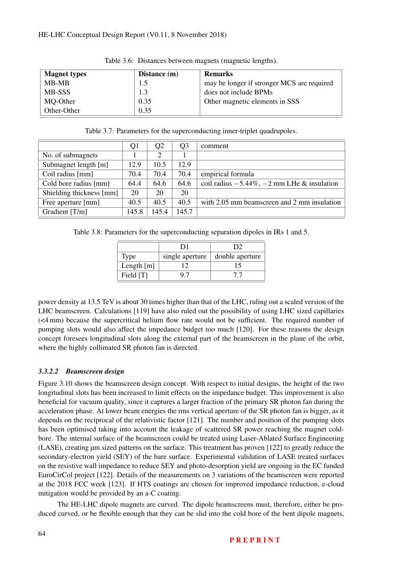
HE-LHC Conceptual Design Report (V0.11, 8 November 2018)
Table 3.6: Distances between magnets (magnetic lengths).
Magnet types Distance (m) RemarksMB-MB 1.5 may be longer if stronger MCS are requiredMB-SSS 1.3 does not include BPMsMQ-Other 0.35 Other magnetic elements in SSSOther-Other 0.35
Table 3.7: Parameters for the superconducting inner-triplet quadrupoles.
Q1 Q2 Q3 commentNo. of submagnets 1 2 1Submagnet length [m] 12.9 10.5 12.9Coil radius [mm] 70.4 70.4 70.4 empirical formulaCold bore radius [mm] 64.4 64.6 64.6 coil radius −5.44%, −2 mm LHe & insulationShielding thickness [mm] 20 20 20Free aperture [mm] 40.5 40.5 40.5 with 2.05 mm beamscreen and 2 mm insulationGradient [T/m] 145.8 145.4 145.7
Table 3.8: Parameters for the superconducting separation dipoles in IRs 1 and 5.
D1 D2Type single aperture double apertureLength [m] 12 15Field [T] 9.7 7.7
power density at 13.5 TeV is about 30 times higher than that of the LHC, ruling out a scaled version of theLHC beamscreen. Calculations [119] have also ruled out the possibility of using LHC sized capillaries(<4 mm) because the supercritical helium flow rate would not be sufficient. The required number ofpumping slots would also affect the impedance budget too much [120]. For these reasons the designconcept foresees longitudinal slots along the external part of the beamscreen in the plane of the orbit,where the highly collimated SR photon fan is directed.
3.3.2.2 Beamscreen design
Figure 3.10 shows the beamscreen design concept. With respect to initial designs, the height of the twolongitudinal slots has been increased to limit effects on the impedance budget. This improvement is alsobeneficial for vacuum quality, since it captures a larger fraction of the primary SR photon fan during theacceleration phase. At lower beam energies the rms vertical aperture of the SR photon fan is bigger, as itdepends on the reciprocal of the relativistic factor [121]. The number and position of the pumping slotshas been optimised taking into account the leakage of scattered SR power reaching the magnet cold-bore. The internal surface of the beamscreen could be treated using Laser-Ablated Surface Engineering(LASE), creating µm sized patterns on the surface. This treatment has proven [122] to greatly reduce thesecondary-electron yield (SEY) of the bare surface. Experimental validation of LASE treated surfaceson the resistive wall impedance to reduce SEY and photo-desorption yield are ongoing in the EC fundedEuroCirCol project [122]. Details of the measurements on 3 variations of the beamscreen were reportedat the 2018 FCC week [123]. If HTS coatings are chosen for improved impedance reduction, e-cloudmitigation would be provided by an a-C coating.
The HE-LHC dipole magnets are curved. The dipole beamscreens must, therefore, either be pro-duced curved, or be flexible enough that they can be slid into the cold bore of the bent dipole magnets,
64P R E P R I N T
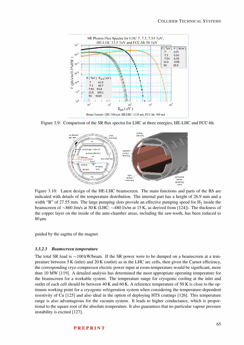
COLLIDER TECHNICAL SYSTEMS
Figure 3.9: Comparison of the SR flux spectra for LHC at three energies, HE-LHC and FCC-hh.
Figure 3.10: Latest design of the HE-LHC beamscreen. The main functions and parts of the BS areindicated with details of the temperature distribution. The internal part has a height of 26.9 mm and awidth “B” of 27.55 mm. The large pumping slots provide an effective pumping speed for H2 inside thebeamscreen of ∼860 l/m/s at 50 K (LHC: ∼480 l/s/m at 15 K, as derived from [124]). The thickness ofthe copper layer on the inside of the ante-chamber areas, including the saw-tooth, has been reduced to80 µm.
guided by the sagitta of the magnet.
3.3.2.3 Beamscreen temperature
The total SR load is ∼100 kW/beam. If the SR power were to be dumped on a beamscreen at a tem-perature between 5 K (inlet) and 20 K (outlet) as in the LHC arc cells, then given the Carnot efficiency,the corresponding cryo-compressor electric power input at room-temperature would be significant, morethan 10 MW [119]. A detailed analysis has determined the most appropriate operating temperature forthe beamscreen for a workable system. The temperature range for cryogenic cooling at the inlet andoutlet of each cell should be between 40 K and 60 K. A reference temperature of 50 K is close to the op-timum working point for a cryogenic refrigeration system when considering the temperature-dependentresistivity of Cu [125] and also ideal in the option of deploying HTS coatings [126]. This temperaturerange is also advantageous for the vacuum system. It leads to higher conductance, which is propor-tional to the square root of the absolute temperature. It also guarantees that no particular vapour pressureinstability is excited [127].
P R E P R I N T65
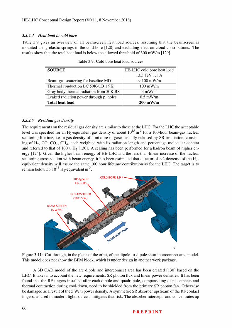
HE-LHC Conceptual Design Report (V0.11, 8 November 2018)
3.3.2.4 Heat load to cold boreTable 3.9 gives an overview of all beamscreen heat load sources, assuming that the beamscreen ismounted using elastic springs in the cold-bore [128] and excluding electron cloud contributions. Theresults show that the total heat load is below the allowed threshold of 300 mW/m [129].
Table 3.9: Cold bore heat load sources
SOURCE HE-LHC cold bore heat load13.5 TeV 1.1 A
Beam-gas scattering for baseline MD ∼ 100 mW/mThermal conduction BC 50K-CB 1.9K 100 mW/mGrey body thermal radiation from 50K BS 3 mW/mLeaked radiation power through p. holes 0.5 mW/mTotal heat load 200 mW/m
3.3.2.5 Residual gas densityThe requirements on the residual gas density are similar to those at the LHC. For the LHC the acceptablelevel was specified for an H2-equivalent gas density of about 1015 m-3 for a 100-hour beam-gas nuclearscattering lifetime, i.e. a gas density of a mixture of gases usually released by SR irradiation, consist-ing of H2, CO, CO2, CH4, each weighted with its radiation length and percentage molecular contentand referred to that of 100% H2 [130]. A scaling has been performed for a hadron beam of higher en-ergy [124]. Given the higher beam energy of HE-LHC and the less-than-linear increase of the nuclearscattering cross-section with beam energy, it has been estimated that a factor of ∼2 decrease of the H2-equivalent density will assure the same 100 hour lifetime contribution as for the LHC. The target is toremain below 5×10¹⁴ H2-equivalent m-3.
I. Bellafont Studies on the beam induced effects in the FCC-hh Slide 1 of 2409/10/2017
BEAM-SCREEN(5 W/m)
END ABSORBER(10÷15 W)
COLD BORE 1.9 KLHC-type RF
FINGERS
Figure 3.11: Cut-through, in the plane of the orbit, of the dipole-to-dipole short interconnect area model.This model does not show the BPM block, which is under design in another work package.
A 3D CAD model of the arc dipole and interconnect area has been created [130] based on theLHC. It takes into account the new requirements, SR photon flux and linear power densities. It has beenfound that the RF fingers installed after each dipole and quadrupole, compensating displacements andthermal contraction during cool-down, need to be shielded from the primary SR photon fan. Otherwisebe damaged as a result of the 5 W/m power density. A symmetric SR absorber upstream of the RF contactfingers, as used in modern light sources, mitigates that risk. The absorber intercepts and concentrates up
66P R E P R I N T
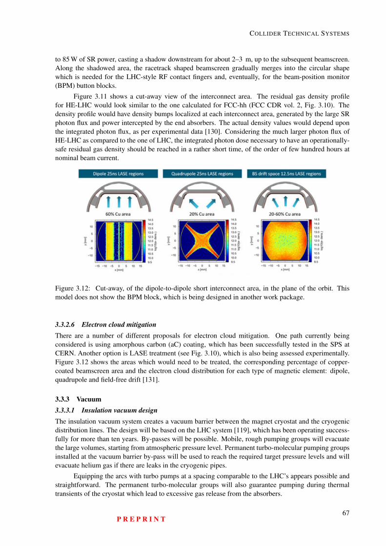
COLLIDER TECHNICAL SYSTEMS
to 85 W of SR power, casting a shadow downstream for about 2–3 m, up to the subsequent beamscreen.Along the shadowed area, the racetrack shaped beamscreen gradually merges into the circular shapewhich is needed for the LHC-style RF contact fingers and, eventually, for the beam-position monitor(BPM) button blocks.
Figure 3.11 shows a cut-away view of the interconnect area. The residual gas density profilefor HE-LHC would look similar to the one calculated for FCC-hh (FCC CDR vol. 2, Fig. 3.10). Thedensity profile would have density bumps localized at each interconnect area, generated by the large SRphoton flux and power intercepted by the end absorbers. The actual density values would depend uponthe integrated photon flux, as per experimental data [130]. Considering the much larger photon flux ofHE-LHC as compared to the one of LHC, the integrated photon dose necessary to have an operationally-safe residual gas density should be reached in a rather short time, of the order of few hundred hours atnominal beam current.
Figure 3.12: Cut-away, of the dipole-to-dipole short interconnect area, in the plane of the orbit. Thismodel does not show the BPM block, which is being designed in another work package.
3.3.2.6 Electron cloud mitigationThere are a number of different proposals for electron cloud mitigation. One path currently beingconsidered is using amorphous carbon (aC) coating, which has been successfully tested in the SPS atCERN. Another option is LASE treatment (see Fig. 3.10), which is also being assessed experimentally.Figure 3.12 shows the areas which would need to be treated, the corresponding percentage of copper-coated beamscreen area and the electron cloud distribution for each type of magnetic element: dipole,quadrupole and field-free drift [131].
3.3.3 Vacuum3.3.3.1 Insulation vacuum designThe insulation vacuum system creates a vacuum barrier between the magnet cryostat and the cryogenicdistribution lines. The design will be based on the LHC system [119], which has been operating success-fully for more than ten years. By-passes will be possible. Mobile, rough pumping groups will evacuatethe large volumes, starting from atmospheric pressure level. Permanent turbo-molecular pumping groupsinstalled at the vacuum barrier by-pass will be used to reach the required target pressure levels and willevacuate helium gas if there are leaks in the cryogenic pipes.
Equipping the arcs with turbo pumps at a spacing comparable to the LHC’s appears possible andstraightforward. The permanent turbo-molecular groups will also guarantee pumping during thermaltransients of the cryostat which lead to excessive gas release from the absorbers.
P R E P R I N T67
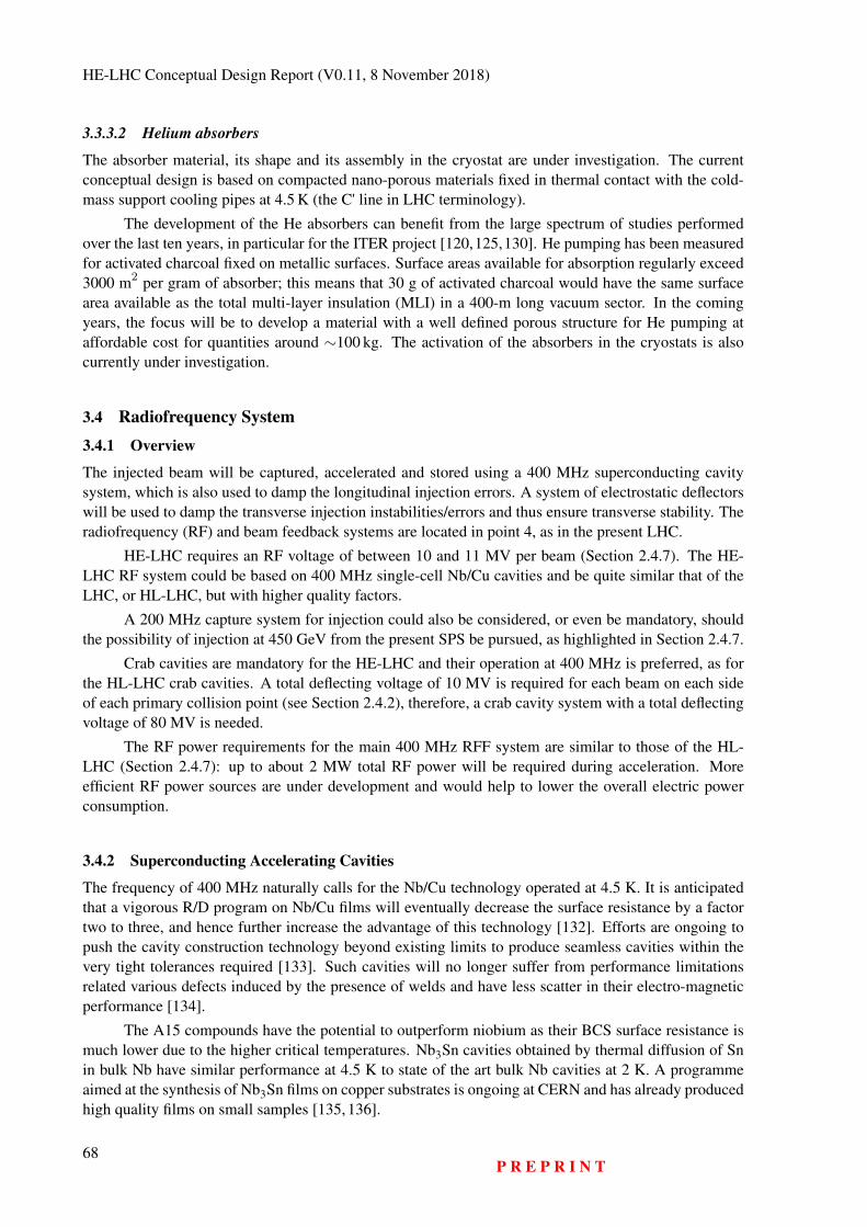
HE-LHC Conceptual Design Report (V0.11, 8 November 2018)
3.3.3.2 Helium absorbers
The absorber material, its shape and its assembly in the cryostat are under investigation. The currentconceptual design is based on compacted nano-porous materials fixed in thermal contact with the cold-mass support cooling pipes at 4.5 K (the C' line in LHC terminology).
The development of the He absorbers can benefit from the large spectrum of studies performedover the last ten years, in particular for the ITER project [120,125,130]. He pumping has been measuredfor activated charcoal fixed on metallic surfaces. Surface areas available for absorption regularly exceed3000 m2 per gram of absorber; this means that 30 g of activated charcoal would have the same surfacearea available as the total multi-layer insulation (MLI) in a 400-m long vacuum sector. In the comingyears, the focus will be to develop a material with a well defined porous structure for He pumping ataffordable cost for quantities around ∼100 kg. The activation of the absorbers in the cryostats is alsocurrently under investigation.
3.4 Radiofrequency System3.4.1 Overview
The injected beam will be captured, accelerated and stored using a 400 MHz superconducting cavitysystem, which is also used to damp the longitudinal injection errors. A system of electrostatic deflectorswill be used to damp the transverse injection instabilities/errors and thus ensure transverse stability. Theradiofrequency (RF) and beam feedback systems are located in point 4, as in the present LHC.
HE-LHC requires an RF voltage of between 10 and 11 MV per beam (Section 2.4.7). The HE-LHC RF system could be based on 400 MHz single-cell Nb/Cu cavities and be quite similar that of theLHC, or HL-LHC, but with higher quality factors.
A 200 MHz capture system for injection could also be considered, or even be mandatory, shouldthe possibility of injection at 450 GeV from the present SPS be pursued, as highlighted in Section 2.4.7.
Crab cavities are mandatory for the HE-LHC and their operation at 400 MHz is preferred, as forthe HL-LHC crab cavities. A total deflecting voltage of 10 MV is required for each beam on each sideof each primary collision point (see Section 2.4.2), therefore, a crab cavity system with a total deflectingvoltage of 80 MV is needed.
The RF power requirements for the main 400 MHz RFF system are similar to those of the HL-LHC (Section 2.4.7): up to about 2 MW total RF power will be required during acceleration. Moreefficient RF power sources are under development and would help to lower the overall electric powerconsumption.
3.4.2 Superconducting Accelerating Cavities
The frequency of 400 MHz naturally calls for the Nb/Cu technology operated at 4.5 K. It is anticipatedthat a vigorous R/D program on Nb/Cu films will eventually decrease the surface resistance by a factortwo to three, and hence further increase the advantage of this technology [132]. Efforts are ongoing topush the cavity construction technology beyond existing limits to produce seamless cavities within thevery tight tolerances required [133]. Such cavities will no longer suffer from performance limitationsrelated various defects induced by the presence of welds and have less scatter in their electro-magneticperformance [134].
The A15 compounds have the potential to outperform niobium as their BCS surface resistance ismuch lower due to the higher critical temperatures. Nb3Sn cavities obtained by thermal diffusion of Snin bulk Nb have similar performance at 4.5 K to state of the art bulk Nb cavities at 2 K. A programmeaimed at the synthesis of Nb3Sn films on copper substrates is ongoing at CERN and has already producedhigh quality films on small samples [135, 136].
68P R E P R I N T
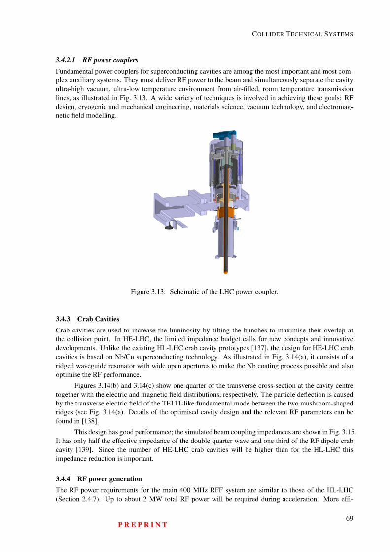
COLLIDER TECHNICAL SYSTEMS
3.4.2.1 RF power couplersFundamental power couplers for superconducting cavities are among the most important and most com-plex auxiliary systems. They must deliver RF power to the beam and simultaneously separate the cavityultra-high vacuum, ultra-low temperature environment from air-filled, room temperature transmissionlines, as illustrated in Fig. 3.13. A wide variety of techniques is involved in achieving these goals: RFdesign, cryogenic and mechanical engineering, materials science, vacuum technology, and electromag-netic field modelling.
Figure 3.13: Schematic of the LHC power coupler.
3.4.3 Crab CavitiesCrab cavities are used to increase the luminosity by tilting the bunches to maximise their overlap atthe collision point. In HE-LHC, the limited impedance budget calls for new concepts and innovativedevelopments. Unlike the existing HL-LHC crab cavity prototypes [137], the design for HE-LHC crabcavities is based on Nb/Cu superconducting technology. As illustrated in Fig. 3.14(a), it consists of aridged waveguide resonator with wide open apertures to make the Nb coating process possible and alsooptimise the RF performance.
Figures 3.14(b) and 3.14(c) show one quarter of the transverse cross-section at the cavity centretogether with the electric and magnetic field distributions, respectively. The particle deflection is causedby the transverse electric field of the TE111-like fundamental mode between the two mushroom-shapedridges (see Fig. 3.14(a). Details of the optimised cavity design and the relevant RF parameters can befound in [138].
This design has good performance; the simulated beam coupling impedances are shown in Fig. 3.15.It has only half the effective impedance of the double quarter wave and one third of the RF dipole crabcavity [139]. Since the number of HE-LHC crab cavities will be higher than for the HL-LHC thisimpedance reduction is important.
3.4.4 RF power generationThe RF power requirements for the main 400 MHz RFF system are similar to those of the HL-LHC(Section 2.4.7). Up to about 2 MW total RF power will be required during acceleration. More effi-
P R E P R I N T69
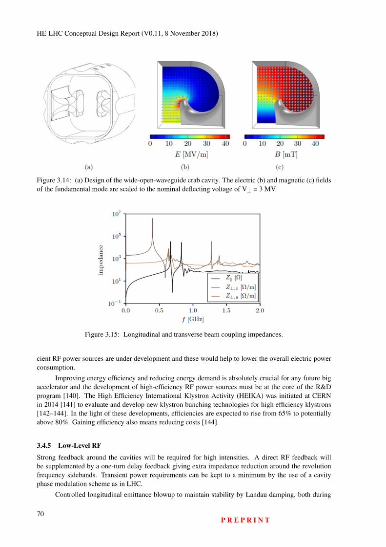
HE-LHC Conceptual Design Report (V0.11, 8 November 2018)
Figure 3.14: (a) Design of the wide-open-waveguide crab cavity. The electric (b) and magnetic (c) fieldsof the fundamental mode are scaled to the nominal deflecting voltage of V⊥ = 3 MV.
Figure 3.15: Longitudinal and transverse beam coupling impedances.
cient RF power sources are under development and these would help to lower the overall electric powerconsumption.
Improving energy efficiency and reducing energy demand is absolutely crucial for any future bigaccelerator and the development of high-efficiency RF power sources must be at the core of the R&Dprogram [140]. The High Efficiency International Klystron Activity (HEIKA) was initiated at CERNin 2014 [141] to evaluate and develop new klystron bunching technologies for high efficiency klystrons[142–144]. In the light of these developments, efficiencies are expected to rise from 65% to potentiallyabove 80%. Gaining efficiency also means reducing costs [144].
3.4.5 Low-Level RF
Strong feedback around the cavities will be required for high intensities. A direct RF feedback willbe supplemented by a one-turn delay feedback giving extra impedance reduction around the revolutionfrequency sidebands. Transient power requirements can be kept to a minimum by the use of a cavityphase modulation scheme as in LHC.
Controlled longitudinal emittance blowup to maintain stability by Landau damping, both during
70P R E P R I N T
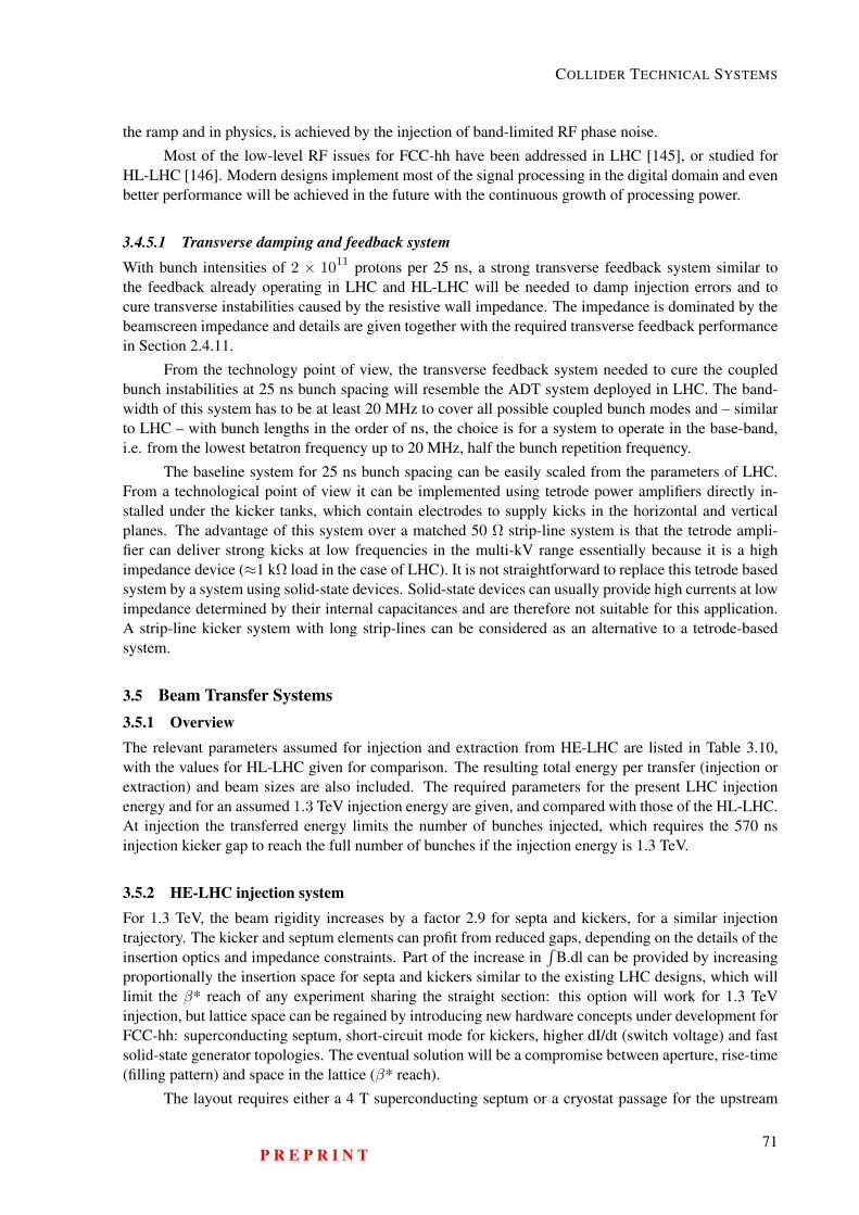
COLLIDER TECHNICAL SYSTEMS
the ramp and in physics, is achieved by the injection of band-limited RF phase noise.
Most of the low-level RF issues for FCC-hh have been addressed in LHC [145], or studied forHL-LHC [146]. Modern designs implement most of the signal processing in the digital domain and evenbetter performance will be achieved in the future with the continuous growth of processing power.
3.4.5.1 Transverse damping and feedback systemWith bunch intensities of 2 × 10¹¹ protons per 25 ns, a strong transverse feedback system similar tothe feedback already operating in LHC and HL-LHC will be needed to damp injection errors and tocure transverse instabilities caused by the resistive wall impedance. The impedance is dominated by thebeamscreen impedance and details are given together with the required transverse feedback performancein Section 2.4.11.
From the technology point of view, the transverse feedback system needed to cure the coupledbunch instabilities at 25 ns bunch spacing will resemble the ADT system deployed in LHC. The band-width of this system has to be at least 20 MHz to cover all possible coupled bunch modes and – similarto LHC – with bunch lengths in the order of ns, the choice is for a system to operate in the base-band,i.e. from the lowest betatron frequency up to 20 MHz, half the bunch repetition frequency.
The baseline system for 25 ns bunch spacing can be easily scaled from the parameters of LHC.From a technological point of view it can be implemented using tetrode power amplifiers directly in-stalled under the kicker tanks, which contain electrodes to supply kicks in the horizontal and verticalplanes. The advantage of this system over a matched 50 Ω strip-line system is that the tetrode ampli-fier can deliver strong kicks at low frequencies in the multi-kV range essentially because it is a highimpedance device (≈1 kΩ load in the case of LHC). It is not straightforward to replace this tetrode basedsystem by a system using solid-state devices. Solid-state devices can usually provide high currents at lowimpedance determined by their internal capacitances and are therefore not suitable for this application.A strip-line kicker system with long strip-lines can be considered as an alternative to a tetrode-basedsystem.
3.5 Beam Transfer Systems3.5.1 OverviewThe relevant parameters assumed for injection and extraction from HE-LHC are listed in Table 3.10,with the values for HL-LHC given for comparison. The resulting total energy per transfer (injection orextraction) and beam sizes are also included. The required parameters for the present LHC injectionenergy and for an assumed 1.3 TeV injection energy are given, and compared with those of the HL-LHC.At injection the transferred energy limits the number of bunches injected, which requires the 570 nsinjection kicker gap to reach the full number of bunches if the injection energy is 1.3 TeV.
3.5.2 HE-LHC injection systemFor 1.3 TeV, the beam rigidity increases by a factor 2.9 for septa and kickers, for a similar injectiontrajectory. The kicker and septum elements can profit from reduced gaps, depending on the details of theinsertion optics and impedance constraints. Part of the increase in
∫B.dl can be provided by increasing
proportionally the insertion space for septa and kickers similar to the existing LHC designs, which willlimit the β* reach of any experiment sharing the straight section: this option will work for 1.3 TeVinjection, but lattice space can be regained by introducing new hardware concepts under development forFCC-hh: superconducting septum, short-circuit mode for kickers, higher dI/dt (switch voltage) and fastsolid-state generator topologies. The eventual solution will be a compromise between aperture, rise-time(filling pattern) and space in the lattice (β* reach).
The layout requires either a 4 T superconducting septum or a cryostat passage for the upstream
P R E P R I N T71
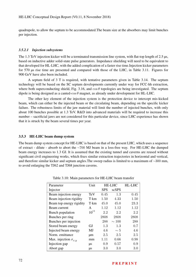
HE-LHC Conceptual Design Report (V0.11, 8 November 2018)
quadrupole, to allow the septum to be accommodated.The beam size at the absorbers may limit bunchesper injection.
3.5.2.1 Injection subsystems
The 1.3 TeV injection kicker will be a terminated transmission line system, with flat-top length of 2.5 µs,based on inductive adder solid-state pulse generators. Impedance shielding will need to be equivalent tothat developed for HL-LHC, with the added complication of a faster rise time.Injection kicker parametersfor 570 µs rise time are presented and compared with those of the LHC, in Table 3.11. Figures for900 GeV have also been included.
A septum field of 3 T is required, with tentative parameters given in Table 3.14. The septumtechnology will be based on the SC septum developments currently under way for FCC-hh extraction,where both superconducting shield, Fig. 3.16, and cos θ topologies are being investigated. The septumdipole is being designed as a canted-cos θ magnet, as already under development for HL-LHC.
The other key element of the injection system is the protection device to intercept mis-kickedbeam, which can either be the injected beam or the circulating beam, depending on the specific kickerfailure. The robustness limits of the jaw material will limit the number of injected bunches, with onlyabout 100 bunches possible at 1.3 TeV. R&D into advanced materials will be required to increase thisnumber – sacrificial jaws are not considered for this particular device, since LHC experience has shownthat it is struck by the beam several times per year.
3.5.3 HE-LHC beam dump system
The beam dump system concept for HE-LHC is based on that of the present LHC, which uses a sequenceof extract - dilute - absorb to abort the ∼700 MJ beam in a loss-free way. For HE-LHC the dumpedbeam energy increases to 1.3 GJ. It is assumed that the existing tunnel and caverns are reused withoutsignificant civil engineering works, which fixes similar extraction trajectories in horizontal and vertical,and therefore similar kicker and septum angles.The sweep radius is limited to a maximum of ∼300 mm,to avoid enlarging the TJ62 and TJ68 junction caverns.
Table 3.10: Main parameters for HE-LHC beam transfer
Parameter Unit HE-LHC HL-LHCInjector SPS scSPSBeam injection energy TeV 0.45 1.3 0.45Beam injection rigidity T·km 1.50 4.33 1.50Beam top energy rigidity T·km 45.0 45.0 23.3Beam current A 1.12 1.12 1.12
Bunch population 1011 2.2 2.2 2.2Bunches per ring 2808 2808 2808Bunches per injection 288 ∼ 100 288Stored beam energy GJ 1.3 1.3 0.7Injected beam energy MJ 4.6 ∼ 5 4.6Norm. emittance µm 2.5 2.5 2.5Max. injection σx,y mm 1.11 0.66 0.98Injection gap µs 0.9 0.57 0.9Abort gap µs 3.0 3.0 3.0
72P R E P R I N T
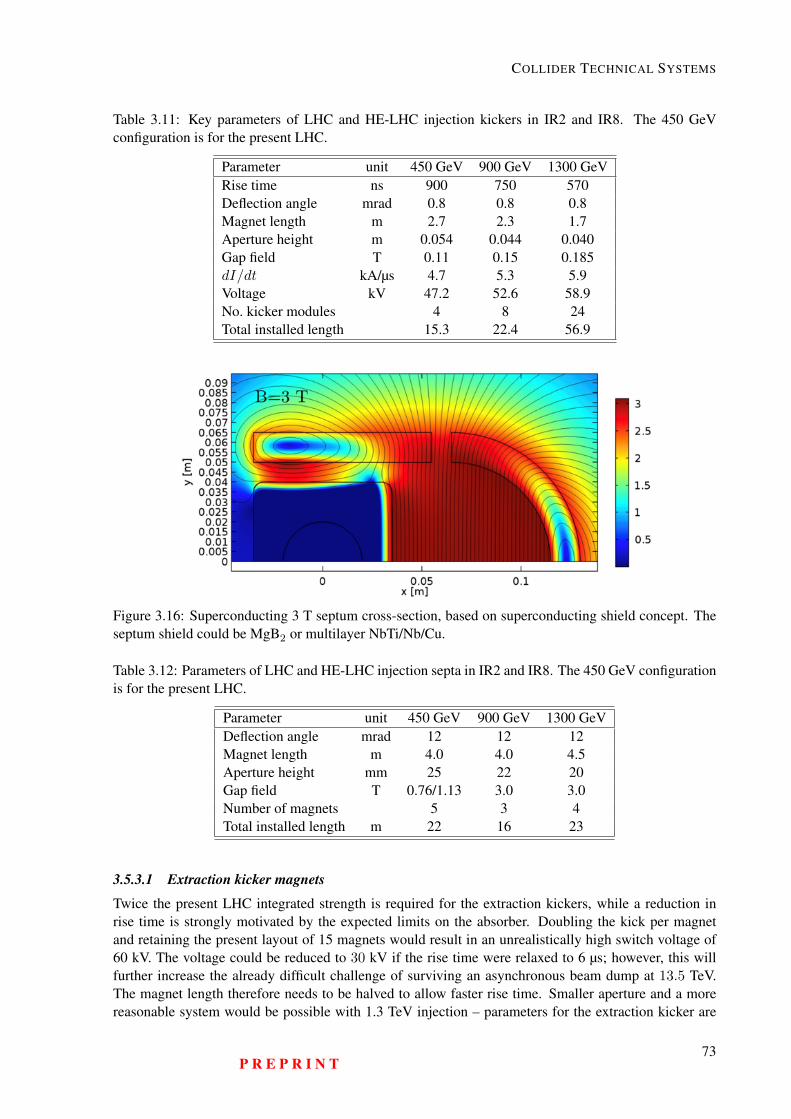
COLLIDER TECHNICAL SYSTEMS
Table 3.11: Key parameters of LHC and HE-LHC injection kickers in IR2 and IR8. The 450 GeVconfiguration is for the present LHC.
Parameter unit 450 GeV 900 GeV 1300 GeVRise time ns 900 750 570Deflection angle mrad 0.8 0.8 0.8Magnet length m 2.7 2.3 1.7Aperture height m 0.054 0.044 0.040Gap field T 0.11 0.15 0.185dI/dt kA/µs 4.7 5.3 5.9Voltage kV 47.2 52.6 58.9No. kicker modules 4 8 24Total installed length 15.3 22.4 56.9
Figure 3.16: Superconducting 3 T septum cross-section, based on superconducting shield concept. Theseptum shield could be MgB2 or multilayer NbTi/Nb/Cu.
Table 3.12: Parameters of LHC and HE-LHC injection septa in IR2 and IR8. The 450 GeV configurationis for the present LHC.
Parameter unit 450 GeV 900 GeV 1300 GeVDeflection angle mrad 12 12 12Magnet length m 4.0 4.0 4.5Aperture height mm 25 22 20Gap field T 0.76/1.13 3.0 3.0Number of magnets 5 3 4Total installed length m 22 16 23
3.5.3.1 Extraction kicker magnets
Twice the present LHC integrated strength is required for the extraction kickers, while a reduction inrise time is strongly motivated by the expected limits on the absorber. Doubling the kick per magnetand retaining the present layout of 15 magnets would result in an unrealistically high switch voltage of60 kV. The voltage could be reduced to 30 kV if the rise time were relaxed to 6 µs; however, this willfurther increase the already difficult challenge of surviving an asynchronous beam dump at 13.5 TeV.The magnet length therefore needs to be halved to allow faster rise time. Smaller aperture and a morereasonable system would be possible with 1.3 TeV injection – parameters for the extraction kicker are
P R E P R I N T73
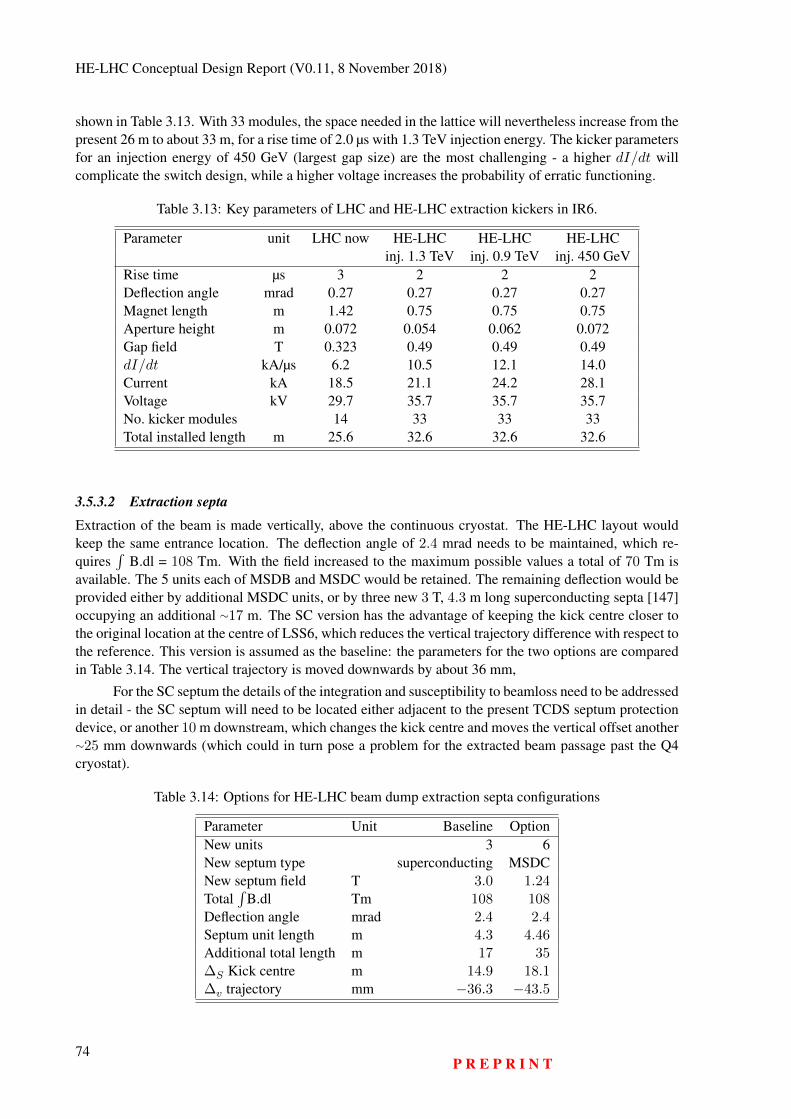
HE-LHC Conceptual Design Report (V0.11, 8 November 2018)
shown in Table 3.13. With 33 modules, the space needed in the lattice will nevertheless increase from thepresent 26 m to about 33 m, for a rise time of 2.0 µs with 1.3 TeV injection energy. The kicker parametersfor an injection energy of 450 GeV (largest gap size) are the most challenging - a higher dI/dt willcomplicate the switch design, while a higher voltage increases the probability of erratic functioning.
Table 3.13: Key parameters of LHC and HE-LHC extraction kickers in IR6.
Parameter unit LHC now HE-LHC HE-LHC HE-LHCinj. 1.3 TeV inj. 0.9 TeV inj. 450 GeV
Rise time µs 3 2 2 2Deflection angle mrad 0.27 0.27 0.27 0.27Magnet length m 1.42 0.75 0.75 0.75Aperture height m 0.072 0.054 0.062 0.072Gap field T 0.323 0.49 0.49 0.49dI/dt kA/µs 6.2 10.5 12.1 14.0Current kA 18.5 21.1 24.2 28.1Voltage kV 29.7 35.7 35.7 35.7No. kicker modules 14 33 33 33Total installed length m 25.6 32.6 32.6 32.6
3.5.3.2 Extraction septa
Extraction of the beam is made vertically, above the continuous cryostat. The HE-LHC layout wouldkeep the same entrance location. The deflection angle of 2.4 mrad needs to be maintained, which re-quires
∫B.dl = 108 Tm. With the field increased to the maximum possible values a total of 70 Tm is
available. The 5 units each of MSDB and MSDC would be retained. The remaining deflection would beprovided either by additional MSDC units, or by three new 3 T, 4.3 m long superconducting septa [147]occupying an additional ∼17 m. The SC version has the advantage of keeping the kick centre closer tothe original location at the centre of LSS6, which reduces the vertical trajectory difference with respect tothe reference. This version is assumed as the baseline: the parameters for the two options are comparedin Table 3.14. The vertical trajectory is moved downwards by about 36 mm,
For the SC septum the details of the integration and susceptibility to beamloss need to be addressedin detail - the SC septum will need to be located either adjacent to the present TCDS septum protectiondevice, or another 10 m downstream, which changes the kick centre and moves the vertical offset another∼25 mm downwards (which could in turn pose a problem for the extracted beam passage past the Q4cryostat).
Table 3.14: Options for HE-LHC beam dump extraction septa configurations
Parameter Unit Baseline OptionNew units 3 6New septum type superconducting MSDCNew septum field T 3.0 1.24Total
∫B.dl Tm 108 108
Deflection angle mrad 2.4 2.4Septum unit length m 4.3 4.46Additional total length m 17 35∆S Kick centre m 14.9 18.1∆v trajectory mm −36.3 −43.5
74P R E P R I N T
COLLIDER TECHNICAL SYSTEMS
3.5.4 Dilution and dump
The dumping system of the LHC consists of extraction kickers (MKB), extraction septa, dilution kickers(MKD), a long transfer line, and a beam dump block, consisting of graphite core with a graded density,varying between 1.77 and 1.2 g/cm3. The beam dilution and beam dump system for the HE-LHC at 13.5TeV beam energy looks possible using a similar concept and layout as for the present LHC system.
The survival of the dump block in case of a beam abort is of paramount concern. In order for thedump block to withstand the impact of an extracted HE-LHC beam, the dilution sweep length has to beincreased, compared with the LHC, as is illustrated in Fig. 3.17.
Figure 3.17: Spiral dilution pattern of extracted bunches at the entrance of the beam-dump absorberblock for the present LHC (left) and the HE-LHC (right).
A promising option in terms of kicker aperture and length is raising the sweep frequency, alongwith a smaller sweep radius. Increasing the dilution sweep length to around 3 m, as shown, requires ahigher dilution-kicker frequency f0, additional kickers with about 4 times the present number of modulesand twice the space, to produce the 2.6 turn spiral. Lowering the density of the inner graphite core from1.2 to 1.0 g/cm3, while increasing the length of this low-density portion to 4 m, seems feasible and couldprovide additional margin.
The tape-wound grain-oriented 50 µm Si steel cores used for the dilution kickers of the LHC showa high saturation field (1.5 T) and acceptable losses up to frequencies of ∼50 kHz. Higher frequenciescould require nanocrystalline steel. The aperture of MKB(V) will be a limit; a higher injection energyallows for smaller aperture.
The possible addition of a SC dilution quadrupole in the extraction line was also studied, but foundnot to be attractive, since such a quadrupole promises little gain, but instead causes integration issues.
Tentative parameters of the HE-LHC dilution kicker systems are given in Table 3.15. The total of38 modules should be compared to 10 for the present LHC.
The performance of the system could be further improved by use of a modified beam dump. For astandard absorber the maximum energy deposition of all bunches occurs at the same longitudinal positioninside the beam dump. This region experiences a much higher temperature rise than the surrounding partsof the beam dump. An improved type of beam absorber would spread out the deposited energy overdifferent longitudinal positions from the front surface of the absorber, thereby reducing the maximumtemperature. One potential implementation is a “mosaic absorber”, i.e., a composite dump blocks madetransversely from sets of different materials or portions of the same material with varying densities. Sucha mosaic beam dump can redistribute the deposited energy since the penetration depth of the energydeposition varies for different materials and densities. A mosaic beam dump was first studied for theFCC-ee [148].
P R E P R I N T75
HE-LHC Conceptual Design Report (V0.11, 8 November 2018)
Table 3.15: Key parameters of HE-LHC vertical and horizontal dilution kickers in IR6.
Parameter unit MKBV MKBHFrequency kHz 44.4 44.4Deflection angle mrad 0.33 0.32Magnet length m 0.70 1.0Coil turns 2 1Aperture height mm 36 32Aperture width mm 66 58Gap field T 0.88 1.02Current kA 23.2 26.1Voltage kV 28.6 28.9No. kicker modules 24 14Total installed length m 23.7 17.9
3.5.5 ConclusionThe HE-LHC injection system is strongly dependent on injection energy. At 1300 GeV there is impact onexperimental β* reach, and the kicker and septum performance are pushed, with SC septa as the baseline.For the dump system, the extraction is feasible if the number of modules is doubled. More space in thelattice is needed for the extraction kickers, and advances in technology are assumed. Detailed studiesof the (protection) absorber limits and extraction kicker rise time are needed, with trade-off betweenfailure probability and consequences. The septa require SC technology and/or a cryostat passage, andthe dilution kicker system will be the most challenging to reach the required performance.
3.6 Beam Diagnostics3.6.1 Requirements and ConceptsThe beam diagnostic requirements for HE-LHC are, to a large extent, defined using the experience gainedfrom LHC operation [149]. These requirements are compared to what is achievable with the state-of-the-art technologies used for modern beam instrumentation systems. A baseline suite of beam diagnosticsfor HE-LHC is proposed based on the outcome of this comparison. Areas where further research anddevelopment is required to fulfil specifications that cannot be met using existing technologies are high-lighted.
The operational scenarios considered for HE-LHC beam diagnostics are:
– Initial beam commissioning, including the need for beam threading to establish circulating beams,the first ramp and squeeze cycle and optics measurement and correction. All typically using a lowintensity, single pilot bunch.
– Machine protection validation for injection and beam dump systems, collimator set-up and loss-map validation, all using a single, nominal intensity, set-up bunch.
– Operation with nominal beams.
The LHC notion of a set-up beam is defined as a beam with an intensity that can never harm machinecomponents as a result of total loss. For LHC, the set-up beam is defined as 5×10¹¹ protons at 450 GeVand 1 × 10¹⁰ protons at 7 TeV. Assuming an HE-LHC top energy of 14 TeV, with a nominal transversebeam size of 0.36 mm (1σ at 1.3 TeV) and 0.18 mm (1σ at 14 TeV) for a typical β=200 m in the HE-LHCarc, the HE-LHC set-up beam is estimated to be 1×10¹¹ and 5×10⁹ protons at injection and top energyrespectively. This sets the lower intensity limit for the operation of all beam diagnostic devices. TheHE-LHC beam parameters relevant for the beam diagnostics are presented in Table 3.16.
76P R E P R I N T
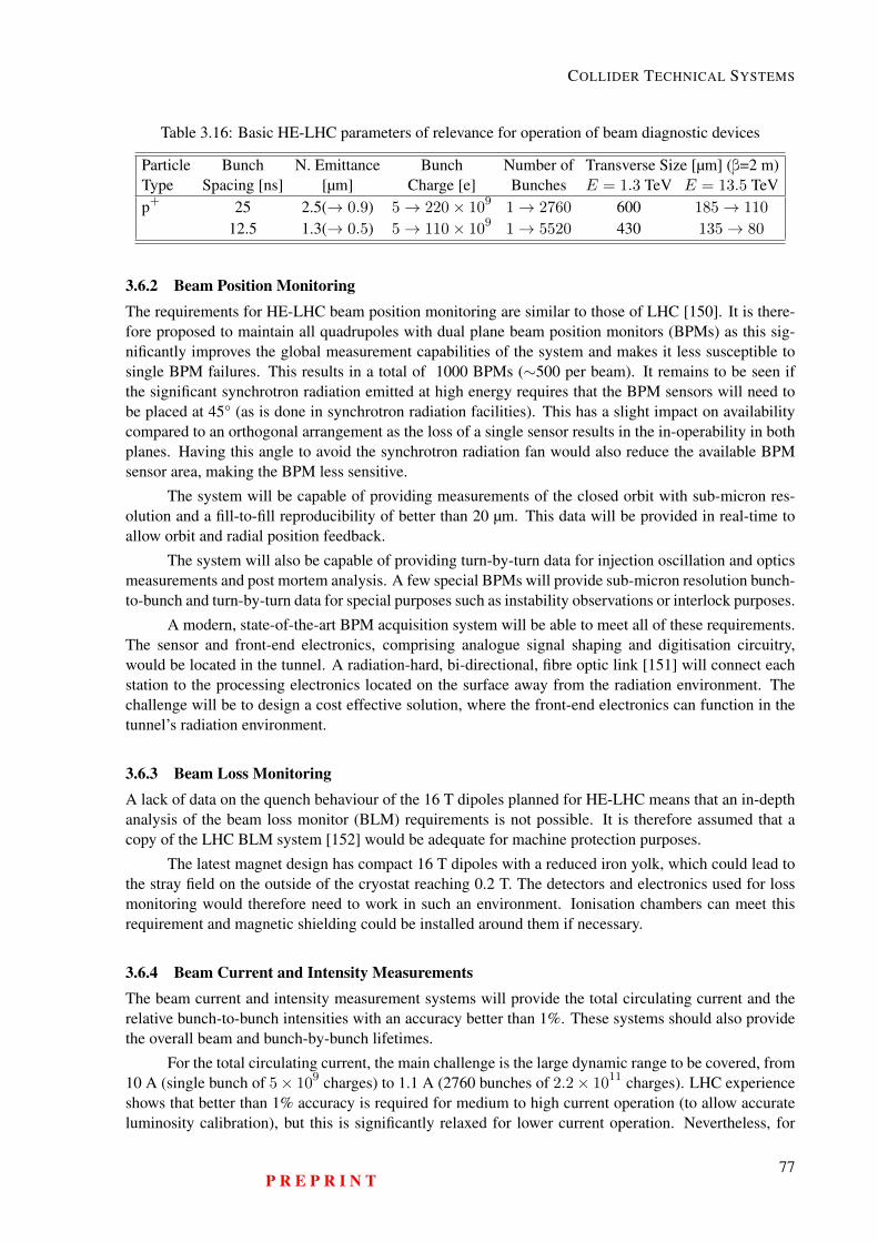
COLLIDER TECHNICAL SYSTEMS
Table 3.16: Basic HE-LHC parameters of relevance for operation of beam diagnostic devices
Particle Bunch N. Emittance Bunch Number of Transverse Size [µm] (β=2 m)Type Spacing [ns] [µm] Charge [e] Bunches E = 1.3 TeV E = 13.5 TeVp+ 25 2.5(→ 0.9) 5→ 220× 109 1→ 2760 600 185→ 110
12.5 1.3(→ 0.5) 5→ 110× 109 1→ 5520 430 135→ 80
3.6.2 Beam Position MonitoringThe requirements for HE-LHC beam position monitoring are similar to those of LHC [150]. It is there-fore proposed to maintain all quadrupoles with dual plane beam position monitors (BPMs) as this sig-nificantly improves the global measurement capabilities of the system and makes it less susceptible tosingle BPM failures. This results in a total of 1000 BPMs (∼500 per beam). It remains to be seen ifthe significant synchrotron radiation emitted at high energy requires that the BPM sensors will need tobe placed at 45° (as is done in synchrotron radiation facilities). This has a slight impact on availabilitycompared to an orthogonal arrangement as the loss of a single sensor results in the in-operability in bothplanes. Having this angle to avoid the synchrotron radiation fan would also reduce the available BPMsensor area, making the BPM less sensitive.
The system will be capable of providing measurements of the closed orbit with sub-micron res-olution and a fill-to-fill reproducibility of better than 20 µm. This data will be provided in real-time toallow orbit and radial position feedback.
The system will also be capable of providing turn-by-turn data for injection oscillation and opticsmeasurements and post mortem analysis. A few special BPMs will provide sub-micron resolution bunch-to-bunch and turn-by-turn data for special purposes such as instability observations or interlock purposes.
A modern, state-of-the-art BPM acquisition system will be able to meet all of these requirements.The sensor and front-end electronics, comprising analogue signal shaping and digitisation circuitry,would be located in the tunnel. A radiation-hard, bi-directional, fibre optic link [151] will connect eachstation to the processing electronics located on the surface away from the radiation environment. Thechallenge will be to design a cost effective solution, where the front-end electronics can function in thetunnel’s radiation environment.
3.6.3 Beam Loss MonitoringA lack of data on the quench behaviour of the 16 T dipoles planned for HE-LHC means that an in-depthanalysis of the beam loss monitor (BLM) requirements is not possible. It is therefore assumed that acopy of the LHC BLM system [152] would be adequate for machine protection purposes.
The latest magnet design has compact 16 T dipoles with a reduced iron yolk, which could lead tothe stray field on the outside of the cryostat reaching 0.2 T. The detectors and electronics used for lossmonitoring would therefore need to work in such an environment. Ionisation chambers can meet thisrequirement and magnetic shielding could be installed around them if necessary.
3.6.4 Beam Current and Intensity MeasurementsThe beam current and intensity measurement systems will provide the total circulating current and therelative bunch-to-bunch intensities with an accuracy better than 1%. These systems should also providethe overall beam and bunch-by-bunch lifetimes.
For the total circulating current, the main challenge is the large dynamic range to be covered, from10 A (single bunch of 5× 10⁹ charges) to 1.1 A (2760 bunches of 2.2× 10¹¹ charges). LHC experienceshows that better than 1% accuracy is required for medium to high current operation (to allow accurateluminosity calibration), but this is significantly relaxed for lower current operation. Nevertheless, for
P R E P R I N T77
HE-LHC Conceptual Design Report (V0.11, 8 November 2018)
machine protection purposes an interlock on the beam intensity during set-up is needed and this requiresa system that has an accuracy and resolution of at least ∼20% of this lower limit (∼2 A). While directcurrent - current transformers (DCCTs) are suitable for the accurate measurement of medium to highcurrents, they have an intrinsic noise floor at around the 1 A level, believed to result from propertiesof the magnetic core material (Barkhausen noise). This makes them unsuitable as machine protectiondevices for HE-LHC. A cryogenic current comparator [153] could therefore be considered to providethis functionality.
A wall current transformer coupled to fast digitisation electronics is proposed for the bunch-by-bunch measurement. A recent upgrade of the LHC system using such technology, combined with nu-merical integration, has already reached the required performance for 25 ns beams [154].
3.6.5 Tune, Chromaticity and CouplingThe requirements for tune, chromaticity and coupling measurements are the same as for LHC. Theprincipal problem to be overcome (and which is already present in the LHC) is the incompatibility of tunemeasurements with a high gain active transverse damping system. Study of the possible implementationof a non-linear transfer function for the transverse damper is therefore proposed. This may lead to someself excitation of betatron oscillations at low amplitudes which will result in slow emittance growth, butthis may be fully compensated by the radiation damping in HE-LHC.
3.6.6 Transverse Profile MeasurementsThe target accuracy for normalised emittance (ε) derivation in HE-LHC is 1%. This folds in both theerror from measurement of the beam size (σ) and knowledge of the beta function (β) at the measurementlocation. If a similar contribution from both is assumed (ε= βσ2), then this translates into an admissibleerror of 0.7% on the beta function and 0.5% on the beam size. For the beam size, this is certainly achallenge towards the end of the fill, where the average size in the arcs is expected to be in the 100 µmrange. In addition to this absolute emittance requirement, a bunch-to-bunch emittance with a relative ac-curacy of 1% (0.5% on the transverse bunch size) is required. Both the absolute emittance measurementand the bunch-to-bunch measurement will be continuous, i.e. capable of providing measurements frominjection, throughout the ramp and during physics.
Due to the high energy density contained in most operational beams, non-intercepting deviceswill be required to measure the beam size. A synchrotron light monitor is the instrument of choice forsuch a high-energy hadron accelerator [155], because there is sufficient visible light generated from astandard bending dipole at all energies (1.3 TeV injection to 14 TeV collision). The variety of sourcesrequired to generate synchrotron radiation in the LHC (undulator at injection, edge radiation during theramp and dipole radiation at top energy), along with the difficulties in reliable calibration that this posescan therefore be avoided. Nevertheless, measuring the small beam size at top energy will be a challengeand requires the synchrotron radiation instrument to be placed in a high beta-function location. Sincethe visible radiation observed is close to the diffraction limit for a large part of the energy range, crosscalibration with other instruments is mandatory to ensure reliable measurements. This cross calibrationis currently provided by intercepting devices (wire scanners), which can only work with a low numberof nominal bunches. Alternative, non-intercepting calibration devices, such as gas jet scanners [156] ora beam gas vertex detector, as are being developed for HL-LHC [157], should therefore be studied.
3.7 Element Support, Survey and Alignment Requirements, and ConceptsThe HE-LHC accelerator elements and their alignment tolerances, discussed in Section 5.9, are similarto those of the existing LHC. Therefore, the concepts, methods and tools of the LHC should be suit-able and sufficient for the HE-LHC, although some improvements may be expected from technologicaldevelopments.
78P R E P R I N T
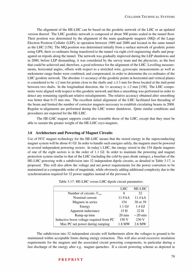
COLLIDER TECHNICAL SYSTEMS
The alignment of the HE-LHC can be based on the geodetic network of the LHC or an updatedversion thereof. The LHC geodetic network is composed of about 500 points sealed in the tunnel floor.Their position was determined by the alignment of the main quadrupole magnets (MQ) of the LargeElectron Positron Collider (LEP), in operation between 1989 and 2000 and located in the same tunnelas the LHC [158]. The MQ position was determined initially from a surface network of geodetic pointsusing GPS, their co-ordinates being transferred to the tunnel via eight civil engineering shafts and prop-agated on tripods along the tunnel. The network was gradually improved during the LEP shutdowns andin 2000, before LEP dismantling, it was considered by the survey team and the physicists, as the bestthat could be achieved and, therefore, a good reference for the alignment of the LHC. Levelling measure-ments, horizontal angles, offsets with respect to a stretched wire, gyroscopic measurements as well asmekometer range-finder were combined, and compensated, in order to determine the co-ordinates of theLHC geodetic network. The absolute 1σ accuracy of the geodetic points in horizontal and vertical planesis considered to be ±2 mm for points close to the shafts and ±4.5 mm for those located at the mid-pointbetween two shafts. In the longitudinal direction, the 1σ accuracy is ±2 mm [158]. The LHC compo-nents were aligned with respect to this geodetic network and then a smoothing was performed in order todetect any remaining significant relative misalignments. The relative accuracy obtained after smoothingwas better than 0.15 mm rms. The excellent initial alignment of the LHC facilitated fast threading ofthe beam and limited the number of corrector magnets necessary to establish circulating beams in 2008.Regular re-alignments are performed during the LHC winter shutdowns. Quite similar conditions andprocedures are expected for the HE-LHC.
The HE-LHC magnet supports could also resemble those of the LHC, except that they must beable to sustain the greater weight of the HE-LHC cryo-magnets.
3.8 Architecture and Powering of Magnet CircuitsUse of FCC magnet technology for the HE-LHC means that the stored energy in the superconductingmagnet system will be about 41 GJ. In order to handle such energies safely, the magnets must be poweredin several independent powering sectors. In today’s LHC, the energy stored in the 154 dipole magnetsof one of the eight sectors is in the order of 1.1 GJ. In order to maintain the powering and magnetprotection system similar to that of the LHC (including the cold by-pass diode ratings), a baseline of theHE-LHC powering with a subdivision into 32 independent dipole circuits, as detailed in Table 3.17, isproposed. This will also allow the voltage and net power requirements for the power converters to bemaintained at a comparable order of magnitude, while obviously adding additional complexity due to thesynchronisation required for 32 power supplies instead of the previous 8.
Table 3.17: HE-LHC versus LHC dipole circuit parameters.
LHC HE-LHCNumber of circuits Ncir 8 32
Nominal current 11.9 kA 11.4 kAMagnets in series 154 38 or 39
Energy 1.1 GJ 1.4 GJApparent inductance 15 H 22 H
Ramp up time 20 min ∼20 minInductive boost voltage required from PC 150 V 230 V
Max PC net power during ramping 1.8 MW 2.6 MW
The subdivision into 32 independent circuits will furthermore allow the voltages to ground to bemaintained within acceptable limits during energy extraction. This will also avoid excessive insulationrequirements for the magnets and the associated circuit powering components, in particular during afast discharge of the energy after e.g. magnet quenches. If a circuit powering scheme as depicted in
P R E P R I N T79
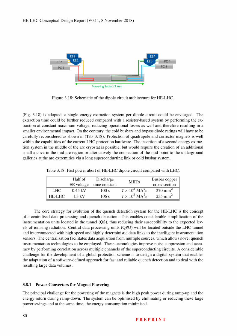
HE-LHC Conceptual Design Report (V0.11, 8 November 2018)
EE4
Powering Sector (3 km)
PC 2 PC 1
EE2EE1 PC 4
PC 3EE3
Figure 3.18: Schematic of the dipole circuit architecture for HE-LHC.
(Fig. 3.18) is adopted, a single energy extraction system per dipole circuit could be envisaged. Theextraction time could be further reduced compared with a resistor-based system by performing the ex-traction at constant maximum voltage, reducing operational losses as well and therefore resulting in asmaller environmental impact. On the contrary, the cold busbars and bypass diode ratings will have to becarefully reconsidered as shown in (Tab. 3.18). Protection of quadrupole and corrector magnets is wellwithin the capabilities of the current LHC protection hardware. The insertion of a second energy extrac-tion system in the middle of the arc cryostat is possible, but would require the creation of an additionalsmall alcove in the mid-arc region or alternatively the connection of the mid-point to the undergroundgalleries at the arc extremities via a long superconducting link or cold busbar system.
Table 3.18: Fast power abort of HE-LHC dipole circuit compared with LHC.
Half ofEE voltage
Dischargetime constant
MIITsBusbar coppercross-section
LHC 0.45 kV 100 s 7× 10³ MA2s 270 mm2
HE-LHC 1.3 kV 106 s 7× 10³ MA2s 235 mm2
The core strategy for evolution of the quench detection system for the HE-LHC is the conceptof a centralised data processing and quench detection. This enables considerable simplification of theinstrumentation units located in the tunnel (QS), thus reducing their susceptibility to the expected lev-els of ionising radiation. Central data processing units (QPU) will be located outside the LHC tunneland interconnected with high speed and highly deterministic data links to the intelligent instrumentationsensors. The centralisation facilitates data acquisition from multiple sources, which allows novel quenchinstrumentation technologies to be employed. These technologies improve noise suppression and accu-racy by performing correlation across multiple channels of the superconducting circuits. A considerablechallenge for the development of a global protection scheme is to design a digital system that enablesthe adaptation of a software-defined approach for fast and reliable quench detection and to deal with theresulting large data volumes.
3.8.1 Power Converters for Magnet Powering
The principal challenge for the powering of the magnets is the high peak power during ramp-up and theenergy return during ramp-down. The system can be optimised by eliminating or reducing these largepower swings and at the same time, the energy consumption minimised.
80P R E P R I N T

COLLIDER TECHNICAL SYSTEMS
3.8.1.1 Power requirements for the main dipole convertersWith four circuits per power sector, there will be 38 or 39 magnets per circuit, resulting in a stored energyin these magnets of about 1.4 GJ. The rated current for the dipole magnets is 11.39 kA and the estimatedequivalent resistance for each magnet circuit is 1 mΩ. There are two options for the ramp-up strategy :
– Constant voltage: a fixed output voltage is applied to the magnets and the current ramps up with aconstant slope (di/dt). The main drawback of this option is that the power requirement during theend of the ramp up is very high. This can be seen from the solid curves in Fig. 3.19a.
– Constant power: the output voltage applied to the magnets is controlled in order to limit the max-imum power during ramp-up. A higher voltage is applied in the first part of the ramp and it isreduced as the current increases (see the solid curves in Fig. 3.19b).
The duration of the ramp has a significant influence on the power converter requirements: theshorter the ramp, the higher the power requirements. The difference in power ratings of the convertersfor a 20' ramp up and a 30' ramp up is shown in Fig. 3.19 where the solid lines are for a 20' ramp anddashed lines for a 30' ramp. The main parameters corresponding to these ramps are given in Table 3.19.
0
2000
4000
6000
8000
10000
12000
0
50
100
150
200
250
300
350
400
450
500
0 500 1000 1500 2000
Current(A)
t (s)
Voltage(V)
0
0.2
0.4
0.6
0.8
1
1.2
1.4
1.6
1.8
2
0
0.5
1
1.5
2
2.5
3
3.5
0 500 1000 1500 2000
Energy(GJ)
t (s)
Power(MW)
20' ramp up
30' ramp up
20' ramp up
30' ramp up
(a) constant-voltage ramp up
0
2000
4000
6000
8000
10000
12000
0
50
100
150
200
250
300
350
400
450
500
0 500 1000 1500 2000
Current(A)
t (s)
Voltage(V)
0
0.2
0.4
0.6
0.8
1
1.2
1.4
1.6
1.8
2
0
0.5
1
1.5
2
2.5
3
3.5
0 500 1000 1500 2000
Energy(GJ)
t (s)
Power(MW)
20' ramp up
30' ramp up
20' ramp up
30' ramp up
(b) constant-power ramp up
Figure 3.19: Voltage applied to the dipole circuit, current in the dipole circuit, power requirement andenergy supplied to the magnets for: (a) constant-voltage ramp; (b) constant-power ramp. Solid linescorrespond to the 20' ramp and dashed lines are for the 30' ramp.
Table 3.19: Maximum voltage, di/dt and active power requirement for the two ramp-up strategies andthe two ramp-up durations.
Ramp strategy Ramp-uptime Max. Voltage Max. di/dt Max. Power req.
Constant voltage 20' 234 V 9.50 A/s 2.66 MWConstant voltage 30' 160 V 6.33 A/s 1.83 MWConstant power 20' 300 V 12.84 A/s 1.52 MWConstant power 30' 300 V 12.84 A/s 0.90 MW
If the total number of dipole circuits is 32, the total power requirements for all dipole circuitswould be 32 times the figures given in the power requirements in Table 3.19 and therefore reducing thepower requirements of each power converter is extremely important. In conclusion, to limit the power
P R E P R I N T81
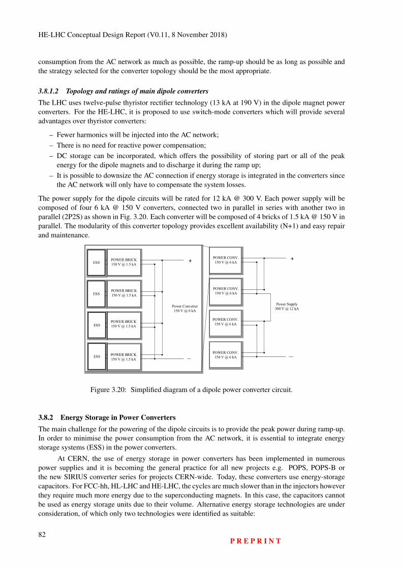
HE-LHC Conceptual Design Report (V0.11, 8 November 2018)
consumption from the AC network as much as possible, the ramp-up should be as long as possible andthe strategy selected for the converter topology should be the most appropriate.
3.8.1.2 Topology and ratings of main dipole convertersThe LHC uses twelve-pulse thyristor rectifier technology (13 kA at 190 V) in the dipole magnet powerconverters. For the HE-LHC, it is proposed to use switch-mode converters which will provide severaladvantages over thyristor converters:
– Fewer harmonics will be injected into the AC network;– There is no need for reactive power compensation;– DC storage can be incorporated, which offers the possibility of storing part or all of the peak
energy for the dipole magnets and to discharge it during the ramp up;– It is possible to downsize the AC connection if energy storage is integrated in the converters since
the AC network will only have to compensate the system losses.
The power supply for the dipole circuits will be rated for 12 kA @ 300 V. Each power supply will becomposed of four 6 kA @ 150 V converters, connected two in parallel in series with another two inparallel (2P2S) as shown in Fig. 3.20. Each converter will be composed of 4 bricks of 1.5 kA @ 150 V inparallel. The modularity of this converter topology provides excellent availability (N+1) and easy repairand maintenance.
+POWER CONV.150 V @ 6 kA
POWER CONV.150 V @ 6 kA
POWER CONV.150 V @ 6 kA
POWER CONV.150 V @ 6 kA
Power Supply300 V @ 12 kA
+POWER BRICK150 V @ 1.5 kA
POWER BRICK150 V @ 1.5 kA
POWER BRICK150 V @ 1.5 kA
POWER BRICK150 V @ 1.5 kA
Power Converter150 V @ 6 kA
ESS
ESS
ESS
ESS
Figure 3.20: Simplified diagram of a dipole power converter circuit.
3.8.2 Energy Storage in Power ConvertersThe main challenge for the powering of the dipole circuits is to provide the peak power during ramp-up.In order to minimise the power consumption from the AC network, it is essential to integrate energystorage systems (ESS) in the power converters.
At CERN, the use of energy storage in power converters has been implemented in numerouspower supplies and it is becoming the general practice for all new projects e.g. POPS, POPS-B orthe new SIRIUS converter series for projects CERN-wide. Today, these converters use energy-storagecapacitors. For FCC-hh, HL-LHC and HE-LHC, the cycles are much slower than in the injectors howeverthey require much more energy due to the superconducting magnets. In this case, the capacitors cannotbe used as energy storage units due to their volume. Alternative energy storage technologies are underconsideration, of which only two technologies were identified as suitable:
82P R E P R I N T
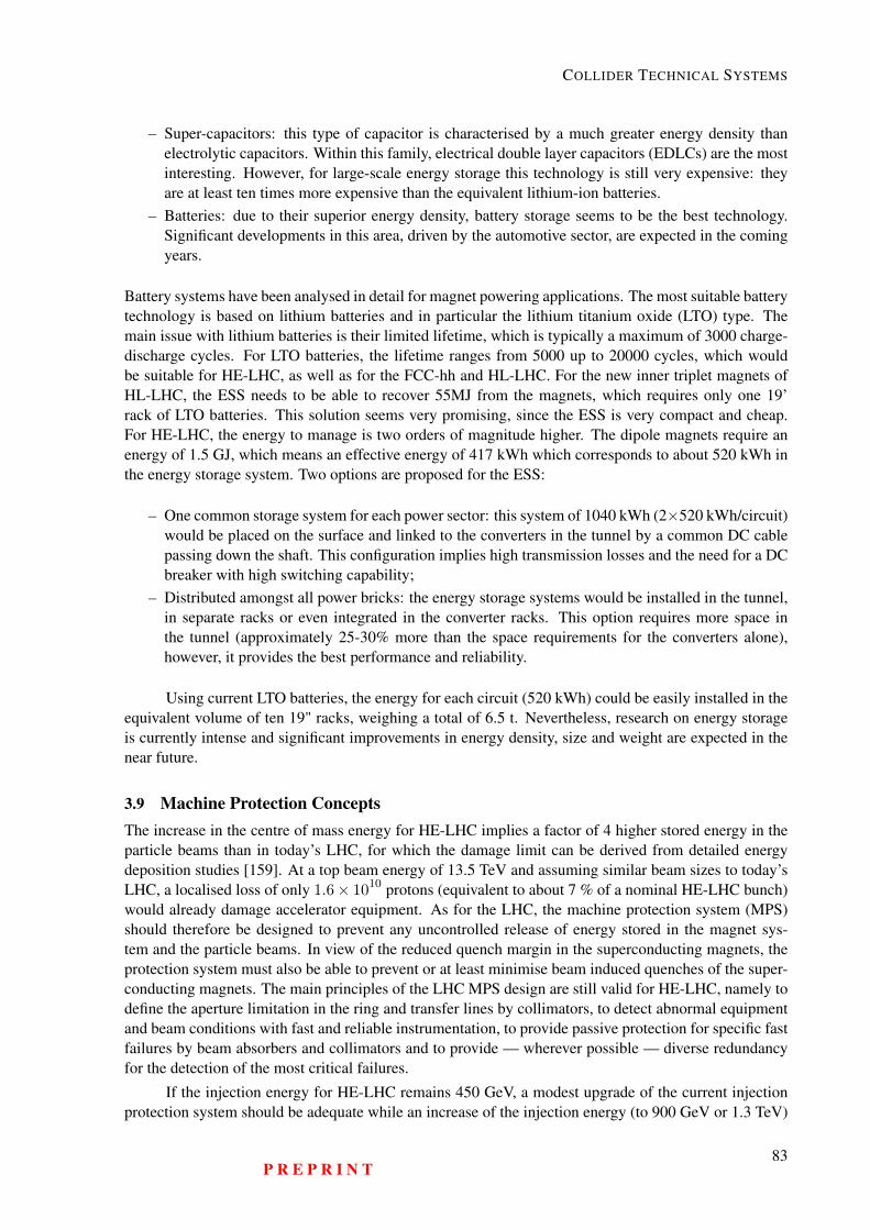
COLLIDER TECHNICAL SYSTEMS
– Super-capacitors: this type of capacitor is characterised by a much greater energy density thanelectrolytic capacitors. Within this family, electrical double layer capacitors (EDLCs) are the mostinteresting. However, for large-scale energy storage this technology is still very expensive: theyare at least ten times more expensive than the equivalent lithium-ion batteries.
– Batteries: due to their superior energy density, battery storage seems to be the best technology.Significant developments in this area, driven by the automotive sector, are expected in the comingyears.
Battery systems have been analysed in detail for magnet powering applications. The most suitable batterytechnology is based on lithium batteries and in particular the lithium titanium oxide (LTO) type. Themain issue with lithium batteries is their limited lifetime, which is typically a maximum of 3000 charge-discharge cycles. For LTO batteries, the lifetime ranges from 5000 up to 20000 cycles, which wouldbe suitable for HE-LHC, as well as for the FCC-hh and HL-LHC. For the new inner triplet magnets ofHL-LHC, the ESS needs to be able to recover 55MJ from the magnets, which requires only one 19’rack of LTO batteries. This solution seems very promising, since the ESS is very compact and cheap.For HE-LHC, the energy to manage is two orders of magnitude higher. The dipole magnets require anenergy of 1.5 GJ, which means an effective energy of 417 kWh which corresponds to about 520 kWh inthe energy storage system. Two options are proposed for the ESS:
– One common storage system for each power sector: this system of 1040 kWh (2×520 kWh/circuit)would be placed on the surface and linked to the converters in the tunnel by a common DC cablepassing down the shaft. This configuration implies high transmission losses and the need for a DCbreaker with high switching capability;
– Distributed amongst all power bricks: the energy storage systems would be installed in the tunnel,in separate racks or even integrated in the converter racks. This option requires more space inthe tunnel (approximately 25-30% more than the space requirements for the converters alone),however, it provides the best performance and reliability.
Using current LTO batteries, the energy for each circuit (520 kWh) could be easily installed in theequivalent volume of ten 19" racks, weighing a total of 6.5 t. Nevertheless, research on energy storageis currently intense and significant improvements in energy density, size and weight are expected in thenear future.
3.9 Machine Protection ConceptsThe increase in the centre of mass energy for HE-LHC implies a factor of 4 higher stored energy in theparticle beams than in today’s LHC, for which the damage limit can be derived from detailed energydeposition studies [159]. At a top beam energy of 13.5 TeV and assuming similar beam sizes to today’sLHC, a localised loss of only 1.6× 10¹⁰ protons (equivalent to about 7 % of a nominal HE-LHC bunch)would already damage accelerator equipment. As for the LHC, the machine protection system (MPS)should therefore be designed to prevent any uncontrolled release of energy stored in the magnet sys-tem and the particle beams. In view of the reduced quench margin in the superconducting magnets, theprotection system must also be able to prevent or at least minimise beam induced quenches of the super-conducting magnets. The main principles of the LHC MPS design are still valid for HE-LHC, namely todefine the aperture limitation in the ring and transfer lines by collimators, to detect abnormal equipmentand beam conditions with fast and reliable instrumentation, to provide passive protection for specific fastfailures by beam absorbers and collimators and to provide — wherever possible — diverse redundancyfor the detection of the most critical failures.
If the injection energy for HE-LHC remains 450 GeV, a modest upgrade of the current injectionprotection system should be adequate while an increase of the injection energy (to 900 GeV or 1.3 TeV)
P R E P R I N T83
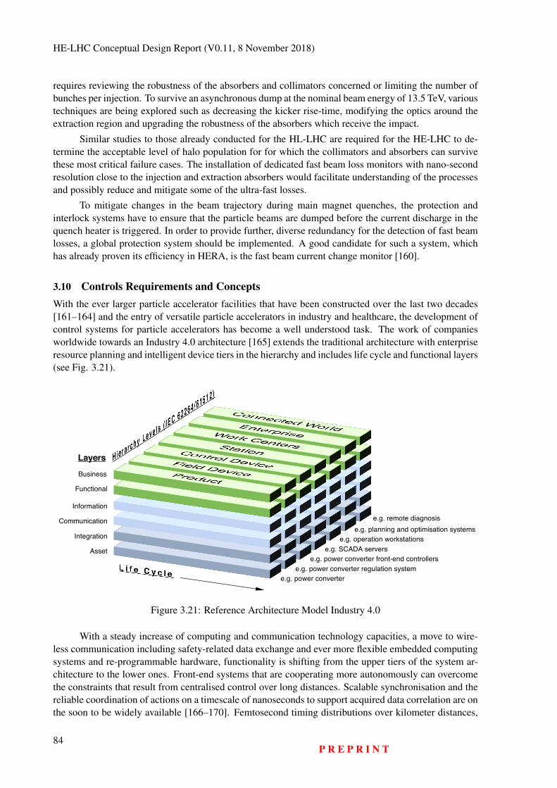
HE-LHC Conceptual Design Report (V0.11, 8 November 2018)
requires reviewing the robustness of the absorbers and collimators concerned or limiting the number ofbunches per injection. To survive an asynchronous dump at the nominal beam energy of 13.5 TeV, varioustechniques are being explored such as decreasing the kicker rise-time, modifying the optics around theextraction region and upgrading the robustness of the absorbers which receive the impact.
Similar studies to those already conducted for the HL-LHC are required for the HE-LHC to de-termine the acceptable level of halo population for for which the collimators and absorbers can survivethese most critical failure cases. The installation of dedicated fast beam loss monitors with nano-secondresolution close to the injection and extraction absorbers would facilitate understanding of the processesand possibly reduce and mitigate some of the ultra-fast losses.
To mitigate changes in the beam trajectory during main magnet quenches, the protection andinterlock systems have to ensure that the particle beams are dumped before the current discharge in thequench heater is triggered. In order to provide further, diverse redundancy for the detection of fast beamlosses, a global protection system should be implemented. A good candidate for such a system, whichhas already proven its efficiency in HERA, is the fast beam current change monitor [160].
3.10 Controls Requirements and ConceptsWith the ever larger particle accelerator facilities that have been constructed over the last two decades[161–164] and the entry of versatile particle accelerators in industry and healthcare, the development ofcontrol systems for particle accelerators has become a well understood task. The work of companiesworldwide towards an Industry 4.0 architecture [165] extends the traditional architecture with enterpriseresource planning and intelligent device tiers in the hierarchy and includes life cycle and functional layers(see Fig. 3.21).
e.g. remote diagnosise.g. planning and optimisation systems
e.g. operation workstationse.g. SCADA servers
e.g. power converter front-end controllerse.g. power converter regulation system
e.g. power converter
Business
Functional
Information
Communication
Integration
Asset
Layers
Figure 3.21: Reference Architecture Model Industry 4.0
With a steady increase of computing and communication technology capacities, a move to wire-less communication including safety-related data exchange and ever more flexible embedded computingsystems and re-programmable hardware, functionality is shifting from the upper tiers of the system ar-chitecture to the lower ones. Front-end systems that are cooperating more autonomously can overcomethe constraints that result from centralised control over long distances. Scalable synchronisation and thereliable coordination of actions on a timescale of nanoseconds to support acquired data correlation are onthe soon to be widely available [166–170]. Femtosecond timing distributions over kilometer distances,
84P R E P R I N T
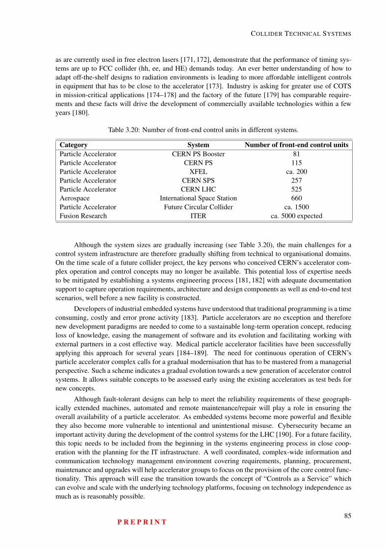
COLLIDER TECHNICAL SYSTEMS
as are currently used in free electron lasers [171, 172], demonstrate that the performance of timing sys-tems are up to FCC collider (hh, ee, and HE) demands today. An ever better understanding of how toadapt off-the-shelf designs to radiation environments is leading to more affordable intelligent controlsin equipment that has to be close to the accelerator [173]. Industry is asking for greater use of COTSin mission-critical applications [174–178] and the factory of the future [179] has comparable require-ments and these facts will drive the development of commercially available technologies within a fewyears [180].
Table 3.20: Number of front-end control units in different systems.
Category System Number of front-end control unitsParticle Accelerator CERN PS Booster 81Particle Accelerator CERN PS 115Particle Accelerator XFEL ca. 200Particle Accelerator CERN SPS 257Particle Accelerator CERN LHC 525Aerospace International Space Station 660Particle Accelerator Future Circular Collider ca. 1500Fusion Research ITER ca. 5000 expected
Although the system sizes are gradually increasing (see Table 3.20), the main challenges for acontrol system infrastructure are therefore gradually shifting from technical to organisational domains.On the time scale of a future collider project, the key persons who conceived CERN’s accelerator com-plex operation and control concepts may no longer be available. This potential loss of expertise needsto be mitigated by establishing a systems engineering process [181, 182] with adequate documentationsupport to capture operation requirements, architecture and design components as well as end-to-end testscenarios, well before a new facility is constructed.
Developers of industrial embedded systems have understood that traditional programming is a timeconsuming, costly and error prone activity [183]. Particle accelerators are no exception and thereforenew development paradigms are needed to come to a sustainable long-term operation concept, reducingloss of knowledge, easing the management of software and its evolution and facilitating working withexternal partners in a cost effective way. Medical particle accelerator facilities have been successfullyapplying this approach for several years [184–189]. The need for continuous operation of CERN’sparticle accelerator complex calls for a gradual modernisation that has to be mastered from a managerialperspective. Such a scheme indicates a gradual evolution towards a new generation of accelerator controlsystems. It allows suitable concepts to be assessed early using the existing accelerators as test beds fornew concepts.
Although fault-tolerant designs can help to meet the reliability requirements of these geograph-ically extended machines, automated and remote maintenance/repair will play a role in ensuring theoverall availability of a particle accelerator. As embedded systems become more powerful and flexiblethey also become more vulnerable to intentional and unintentional misuse. Cybersecurity became animportant activity during the development of the control systems for the LHC [190]. For a future facility,this topic needs to be included from the beginning in the systems engineering process in close coop-eration with the planning for the IT infrastructure. A well coordinated, complex-wide information andcommunication technology management environment covering requirements, planning, procurement,maintenance and upgrades will help accelerator groups to focus on the provision of the core control func-tionality. This approach will ease the transition towards the concept of “Controls as a Service” whichcan evolve and scale with the underlying technology platforms, focusing on technology independence asmuch as is reasonably possible.
P R E P R I N T85
HE-LHC Conceptual Design Report (V0.11, 8 November 2018)
As is the case in other domains [191], support for closed-loop settings optimisation and includingan accelerator physics point of view towards controls will help to improve the efficiency of the accel-erator complex [192]. This will become possible with the higher computing power and data exchangecapacities, more flexible analysis using big-data approaches, the introduction of machine learning, modeldriven approaches and an end-to-end cost/benefit sensitivity analysis.
3.11 Radiation Environment3.11.1 IntroductionRadiation levels in the collider scale with energy and, as LHC has shown, degradation of componentsexposed to radiation can become a show stopper. A structured approach for radiation hardness assurance(RHA) will ensure that the electronics and materials developed perform to their design specificationsafter exposure to the radiation in the collider environment. Two complementary approaches are needed:the reduction of the dose to equipment by shielding and developing fault tolerant or radiation resistantelectronics and equipment.
3.11.2 Reference Radiation LevelsRadiation to electronics (R2E) is an issue in the design of any high energy and high intensity ma-chine [193]. Radiation effects in electronic devices can be divided into two main categories: cumulativeeffects and stochastic effects (Single Event Effects - SEE). Cumulative effects are proportional to thetotal ionising dose (TID) - the damage induced by ionising radiation, and the 1 MeV neutron-equivalentfluence which concerns displacement damage. On the other hand, SEE, which are proportional to thehigh energy hadron fluence (HEH, i.e. hadrons with energies> 20 MeV), are due to the direct or indirectionisation by a single particle which is able to deposit sufficient energy to disturb the operation of thedevice. SEE can only be defined by their probability to occur and the effect strongly depends on thedevice, the intensity and the kind of radiation field. An accurate specification of the radiation levels inareas critical for electronics is essential for the design of the accelerator.
Monte Carlo (MC) simulation is an indispensable tool to evaluate the impact of radiation on themachine equipment, but it relies on both a refined implementation of physics models of the particleinteraction with matter and an accurate 3D-description of the region of interest. In this context, FLUKA[194,195] which is widely employed at CERN, is a well benchmarked, multi-purpose and fully integratedparticle physics MC code for calculations of particle transport and interactions with matter. For a highintensity and high energy machine like the HE-LHC, typical sources of radiation are luminosity debris,direct losses on collimators and dumps and beam interactions with the residual gas in the vacuum [196].
A FLUKA model of the HE-LHC arc, for both optics solutions (18× 90 and 23× 90) is currentlyunder development. Although FLUKA simulation allows a detailed study of the radiation environment,taking the infrastructure around the accelerator into acount, the order of magnitude of the radiationlevels can be estimated from the measured and calculated values from LHC. Scaling with the beamenergy, beam current and assuming the maximum residual gas-density design value of 1.0×10¹⁵ H2/m3
(corresponding to beam lifetime of 100 h), the annual HEH fluence and absorbed dose distribution atthe locations where electronic racks are typically placed below the magnets in the arc are expected tobe ∼ 4 × 1010 cm−2y−1 and ∼ 80 Gy y−1 respectively. These values are about a factor 2.5 lower thanFCC-hh, assuming the same residual gas-density. Such values impose serious constraints on the selectionand qualification of electronic components for operation in distributed systems in the machine arc.
It is important to underline that the values reported above refer to an extreme situation in whichthe residual gas-density represents an upper limit which should not be exceeded. LHC experience hasshown that the residual gas-density can be factors of several hundreds lower, leading to a better vacuumquality and therefore to lower radiation levels.
Finally, the residual gas-density plays an important role in the HE-LHC design because of the in-
86P R E P R I N T
COLLIDER TECHNICAL SYSTEMS
frastructure, which is fixed by the current machine layout. Indeed, in the case of FCC-hh, ad-hoc shieldedalcoves for electronics were designed to ensure adequate protection of all the electronic systems fromthe severe radiation levels expected in the arc, even for a residual gas-density of 1.0×10¹⁵ H2/m3. Withregard to HE-LHC, the existing RE alcoves need to be studied with FLUKA simulations, to verify thatthe shielding already available provides adequate protection and, potentially, to support civil engineeringstudies for the redesign of these areas.
3.11.3 Radiation HardnessRadiation hardness assurance (RHA) comprises all if the activities undertaken to ensure that the elec-tronics and materials perform to their design specification after exposure to the HE-LHC radiation envi-ronment. Several strategies are being developed.
As is the case for the present LHC machine, the power converters, beam position and beam lossmonitors (BPM and BLM) and quench protection system (QPS) have to be close to the acceleratoritself. Such equipment is mainly based on commercial-off-the-shelf (COTS) components and thereforethe equipment needs to be qualified for use in the radiation environment. CERN’s current irradiationfacilities are an essential means to independently assess the radiation hardness of electronic components,assemblies and systems in the collider environment. An analysis of the main shortcomings of CERN’sfacilities and possible solutions has been carried out and the main conclusions are outlined elsewhere[197]. For cumulative TID effects, facilities such as the CC60 [198] and GIF++ [199] will have to beupgraded with more powerful sources. This will allow higher doses to be reached in shorter times andit has the potential of running more users in parallel. For the assessment of the single event effects, theCHARM facility [200] can be upgraded by increasing the beam intensity and the space available for theusers to make parallel and multiple testing possible. The extensive qualification programme requiredneeds the upgrade of existing and well-known irradiation facilities, by collaboratively exploiting theexpertise and test capacity worldwide.
The HE-LHC RHA strategy is founded on a full-availability approach based on: (i) a remotecontrol approach, moving the processing tasks away from the equipment under control and (ii) failureself-diagnosis, online hot swapping and remote handling. Therefore system designs are based on amodular approach that will allow switching to a redundant sub-system without any impact on operation.This will be particularly beneficial for transient errors, which can typically be corrected with a reset. Theapproach will also relax the constraints on the error qualification limits, which will be obtained throughaccelerated radiation testing. In the case of events which cause permanent effects such as hard SEEs(occurring stochastically) or cumulative damage, online hot-swapping will need to be complemented bythe substitution of the faulty board. This procedure will need to be carefully optimised, especially forcumulative damage, where similar sub-systems exposed to similar radiation levels are expected to fail ataround the same time. Remote handling and the possibility of replacement of faulty units with spareswhich have been stored in radiation-safe areas, is one way to mitigate the risk.
The proposed scheme will bring benefits from the use of a selected set of semiconductor compo-nents that can be used in different sub-systems. The related procurement and qualification processes canbe optimised and the impact of variability in sensitivity across batches and deliveries can be reduced. Inspecific cases, the use of radiation-hardened solutions at component level (e.g. FPGA) can be consideredin combination with the use of COTS devices.
Finally, intensive work on radiation hardening of electronics, components, materials and detec-tors, as it is currently happening for HL-LHC, will continue in parallel to technology scouting and earlytechnology analysis to cope with the rapid advance of electronics development and market trends. Keytechnology areas for HE-LHC include, to name but a few, the development of radiation-hard, fast andhigh-bandwidth communication links [201], as they allow to reduce the burden and complexity of thesystems deployed in radiation areas, improved radiation performance and the accompanying miniaturi-sation of on-detector Application-Specific Integrated Circuits (ASICs) [201], and development of novel
P R E P R I N T87

HE-LHC Conceptual Design Report (V0.11, 8 November 2018)
concepts for Ultra High Radiation Dosimetry [202]
88P R E P R I N T
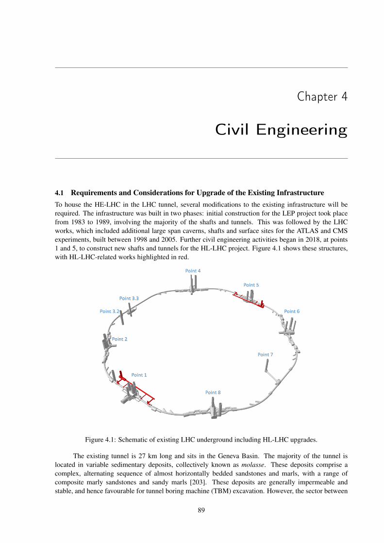
Chapter 4
Civil Engineering
4.1 Requirements and Considerations for Upgrade of the Existing InfrastructureTo house the HE-LHC in the LHC tunnel, several modifications to the existing infrastructure will berequired. The infrastructure was built in two phases: initial construction for the LEP project took placefrom 1983 to 1989, involving the majority of the shafts and tunnels. This was followed by the LHCworks, which included additional large span caverns, shafts and surface sites for the ATLAS and CMSexperiments, built between 1998 and 2005. Further civil engineering activities began in 2018, at points1 and 5, to construct new shafts and tunnels for the HL-LHC project. Figure 4.1 shows these structures,with HL-LHC-related works highlighted in red.
Figure 4.1: Schematic of existing LHC underground including HL-LHC upgrades.
The existing tunnel is 27 km long and sits in the Geneva Basin. The majority of the tunnel islocated in variable sedimentary deposits, collectively known as molasse. These deposits comprise acomplex, alternating sequence of almost horizontally bedded sandstones and marls, with a range ofcomposite marly sandstones and sandy marls [203]. These deposits are generally impermeable andstable, and hence favourable for tunnel boring machine (TBM) excavation. However, the sector between
89
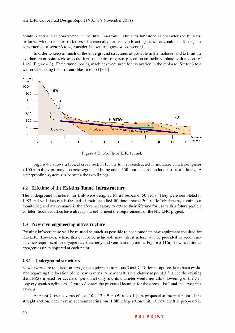
HE-LHC Conceptual Design Report (V0.11, 8 November 2018)
points 3 and 4 was constructed in the Jura limestone. The Jura limestone is characterised by karstfeatures, which includes instances of chemically formed voids acting as water conduits. During theconstruction of sector 3 to 4, considerable water ingress was observed.
In order to keep as much of the underground structures as possible in the molasse, and to limit theoverburden at point 4 close to the Jura, the entire ring was placed on an inclined plane with a slope of1.4% (Figure 4.2). Three tunnel boring machines were used for excavation in the molasse. Sector 3 to 4was created using the drill-and-blast method [204].
Figure 4.2: Profile of LHC tunnel.
Figure 4.3 shows a typical cross-section for the tunnel constructed in molasse, which comprisesa 100 mm thick primary concrete segmental lining and a 150 mm thick secondary cast in-situ lining. Awaterproofing system sits between the two linings.
4.2 Lifetime of the Existing Tunnel InfrastructureThe underground structures for LEP were designed for a lifespan of 50 years. They were completed in1989 and will thus reach the end of their specified lifetime around 2040. Refurbishment, continuousmonitoring and maintenance is therefore necessary to extend their lifetime for use with a future particlecollider. Such activities have already started to meet the requirements of the HL-LHC project.
4.3 New civil engineering infrastructureExisting infrastructure will be re-used as much as possible to accommodate new equipment required forHE-LHC. However, where this cannot be achieved, new infrastructure will be provided to accommo-date new equipment for cryogenics, electricity and ventilation systems. Figure 5.11(a) shows additionalcryogenics units required at each point.
4.3.1 Underground structuresNew caverns are required for cryogenic equipment at points 3 and 7. Different options have been evalu-ated regarding the location of the new caverns. A new shaft is mandatory at point 3.3, since the existingshaft PZ33 is used for access of personnel only and its diameter would not allow lowering of the 7 mlong cryogenics cylinders. Figure ?? shows the proposed location for the access shaft and the cryogeniccaverns.
At point 7, two caverns of size 10 x 13 x 9 m (W x L x H) are proposed at the mid-point of thestraight section, each cavern accommodating one 1.8K refrigeration unit. A new shaft is proposed in
90P R E P R I N T

CIVIL ENGINEERING
Figure 4.3: Typical LHC tunnel cross-section.
the proximity of UJ76 cavern to allow access for installation of the new equipment into the undergroundstructures (Figure ??). Alternatively, the existing PM76 shaft and the connection tunnel TZ76 can beused for access if emptied of all equipment. One advantage of providing a new shaft is allowing con-struction to start while LHC machine is in operation. This is the same approach adopted for HL-LHCcivil engineering.
At point 2, existing caverns could possibly be used to accommodate the new equipment. If thespace does not allow installing additional equipment, a new cavern will be provided. To transport thenew equipment into the tunnel at point 2, either existing shafts PM25 or PMI2 can be used or a new shaftcan be provided. As mentioned in section 4.1, new caverns and shafts are being constructed at points 1and 5 for HL-LHC, which could be used to install the supplementary cryogenics equipment required forHE-LHC. Otherwise, new caverns will be required. New alcoves for electrical equipment are requiredat points 3 and 7 to supply the cryogenic installations. Additional upgrades might be needed at otherlocations depending on the power consumption and reliability of the existing network. Additional spacein the underground caverns was allocated for cooling equipment. Table 4.1 shows the dimensions ofunderground structures required for HE-LHC.
Localised parts of the tunnel lining will be broken out to facilitate the excavation of the new spaces.This requires the removal of all equipment from the LHC tunnel. In addition, this activity introduces therisk of water ingress and structural damage. Temporary propping in the vicinity of the breakouts willbe required. Excavating in the Jura limestone should be avoided, since the risk for water ingress is veryhigh in this location; this affects the required works at point 3. Additional ground investigations may be
P R E P R I N T91
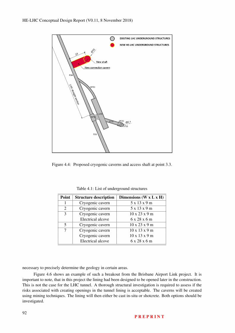
HE-LHC Conceptual Design Report (V0.11, 8 November 2018)
Figure 4.4: Proposed cryogenic caverns and access shaft at point 3.3.
Table 4.1: List of underground structures
Point Structure description Dimensions (W x L x H)1 Cryogenic cavern 5 x 13 x 9 m2 Cryogenic cavern 5 x 13 x 9 m3 Cryogenic cavern 10 x 23 x 9 m
Electrical alcove 6 x 28 x 6 m5 Cryogenic cavern 10 x 23 x 9 m7 Cryogenic cavern 10 x 13 x 9 m
Cryogenic cavern 10 x 13 x 9 mElectrical alcove 6 x 28 x 6 m
necessary to precisely determine the geology in certain areas.
Figure 4.6 shows an example of such a breakout from the Brisbane Airport Link project. It isimportant to note, that in this project the lining had been designed to be opened later in the construction.This is not the case for the LHC tunnel. A thorough structural investigation is required to assess if therisks associated with creating openings in the tunnel lining is acceptable. The caverns will be createdusing mining techniques. The lining will then either be cast in-situ or shotcrete. Both options should beinvestigated.
92P R E P R I N T
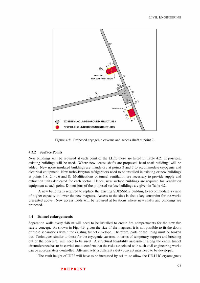
CIVIL ENGINEERING
Figure 4.5: Proposed cryogenic caverns and access shaft at point 7.
4.3.2 Surface Points
New buildings will be required at each point of the LHC; these are listed in Table 4.2. If possible,existing buildings will be used. Where new access shafts are proposed, head shaft buildings will beadded. New noise insulated buildings are mandatory at points 3 and 7 to accommodate cryogenic andelectrical equipment. New turbo-Brayton refrigerators need to be installed in existing or new buildingsat points 1.8, 2, 4, 6 and 8. Modifications of tunnel ventilation are necessary to provide supply andextraction units dedicated for each sector. Hence, new surface buildings are required for ventilationequipment at each point. Dimensions of the proposed surface buildings are given in Table 4.2.
A new building is required to replace the existing SDI2/SMI2 building to accommodate a craneof higher capacity to lower the new magnets. Access to the sites is also a key constraint for the workspresented above. New access roads will be required at locations where new shafts and buildings areproposed.
4.4 Tunnel enlargementsSeparation walls every 548 m will need to be installed to create fire compartments for the new firesafety concept. As shown in Fig. 4.9, given the size of the magnets, it is not possible to fit the doorsof these separations within the existing tunnel envelope. Therefore, parts of the lining must be brokenout. Techniques similar to those for the cryogenic caverns, in terms of temporary support and breakingout of the concrete, will need to be used. A structural feasibility assessment along the entire tunnelcircumference has to be carried out to confirm that the risks associated with such civil engineering workscan be appropriately controlled. Alternatively, a different safety concept may need to be developed.
The vault height of UJ22 will have to be increased by ≈1 m, to allow the HE-LHC cryomagnets
P R E P R I N T93
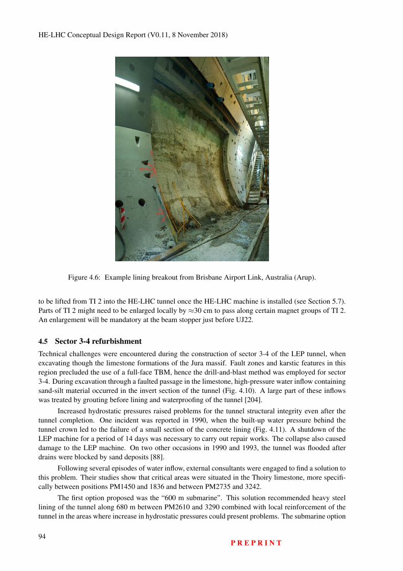
HE-LHC Conceptual Design Report (V0.11, 8 November 2018)
Figure 4.6: Example lining breakout from Brisbane Airport Link, Australia (Arup).
to be lifted from TI 2 into the HE-LHC tunnel once the HE-LHC machine is installed (see Section 5.7).Parts of TI 2 might need to be enlarged locally by ≈30 cm to pass along certain magnet groups of TI 2.An enlargement will be mandatory at the beam stopper just before UJ22.
4.5 Sector 3-4 refurbishmentTechnical challenges were encountered during the construction of sector 3-4 of the LEP tunnel, whenexcavating though the limestone formations of the Jura massif. Fault zones and karstic features in thisregion precluded the use of a full-face TBM, hence the drill-and-blast method was employed for sector3-4. During excavation through a faulted passage in the limestone, high-pressure water inflow containingsand-silt material occurred in the invert section of the tunnel (Fig. 4.10). A large part of these inflowswas treated by grouting before lining and waterproofing of the tunnel [204].
Increased hydrostatic pressures raised problems for the tunnel structural integrity even after thetunnel completion. One incident was reported in 1990, when the built-up water pressure behind thetunnel crown led to the failure of a small section of the concrete lining (Fig. 4.11). A shutdown of theLEP machine for a period of 14 days was necessary to carry out repair works. The collapse also causeddamage to the LEP machine. On two other occasions in 1990 and 1993, the tunnel was flooded afterdrains were blocked by sand deposits [88].
Following several episodes of water inflow, external consultants were engaged to find a solution tothis problem. Their studies show that critical areas were situated in the Thoiry limestone, more specifi-cally between positions PM1450 and 1836 and between PM2735 and 3242.
The first option proposed was the “600 m submarine”. This solution recommended heavy steellining of the tunnel along 680 m between PM2610 and 3290 combined with local reinforcement of thetunnel in the areas where increase in hydrostatic pressures could present problems. The submarine option
94P R E P R I N T
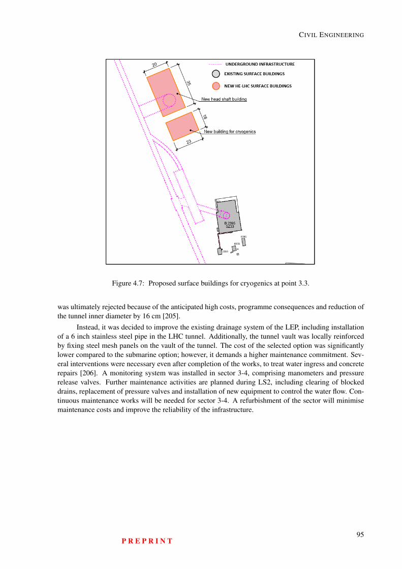
CIVIL ENGINEERING
Figure 4.7: Proposed surface buildings for cryogenics at point 3.3.
was ultimately rejected because of the anticipated high costs, programme consequences and reduction ofthe tunnel inner diameter by 16 cm [205].
Instead, it was decided to improve the existing drainage system of the LEP, including installationof a 6 inch stainless steel pipe in the LHC tunnel. Additionally, the tunnel vault was locally reinforcedby fixing steel mesh panels on the vault of the tunnel. The cost of the selected option was significantlylower compared to the submarine option; however, it demands a higher maintenance commitment. Sev-eral interventions were necessary even after completion of the works, to treat water ingress and concreterepairs [206]. A monitoring system was installed in sector 3-4, comprising manometers and pressurerelease valves. Further maintenance activities are planned during LS2, including clearing of blockeddrains, replacement of pressure valves and installation of new equipment to control the water flow. Con-tinuous maintenance works will be needed for sector 3-4. A refurbishment of the sector will minimisemaintenance costs and improve the reliability of the infrastructure.
P R E P R I N T95
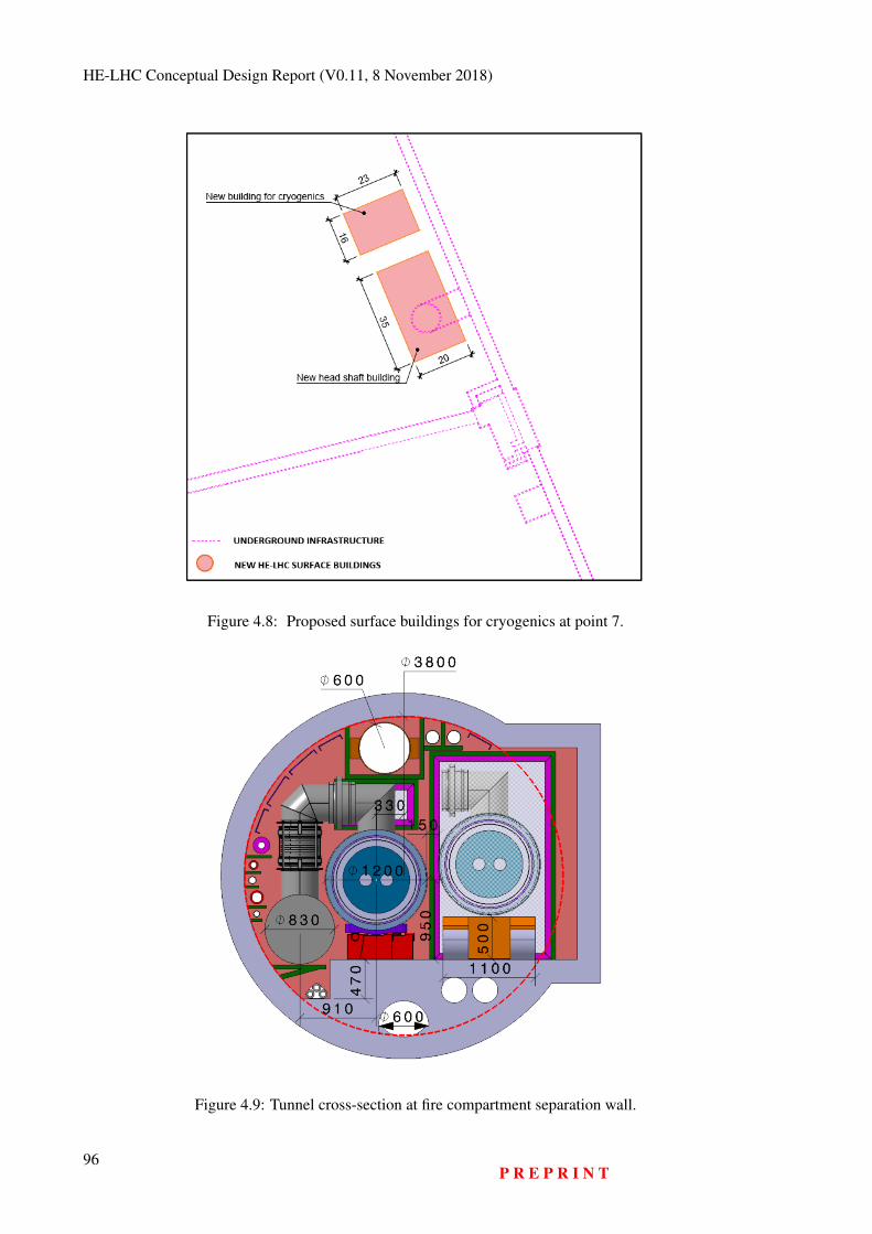
HE-LHC Conceptual Design Report (V0.11, 8 November 2018)
Figure 4.8: Proposed surface buildings for cryogenics at point 7.
Figure 4.9: Tunnel cross-section at fire compartment separation wall.
96P R E P R I N T
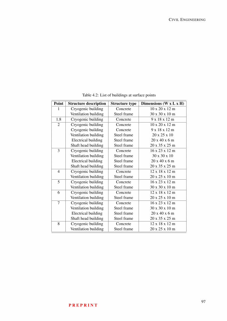
CIVIL ENGINEERING
Table 4.2: List of buildings at surface points
Point Structure description Structure type Dimensions (W x L x H)1 Cryogenic building Concrete 10 x 20 x 12 m
Ventilation building Steel frame 30 x 30 x 10 m1.8 Cryogenic building Concrete 9 x 18 x 12 m2 Cryogenic building Concrete 10 x 20 x 12 m
Cryogenic building Concrete 9 x 18 x 12 mVentilation building Steel frame 20 x 25 x 10Electrical building Steel frame 20 x 40 x 6 mShaft head building Steel frame 20 x 35 x 25 m
3 Cryogenic building Concrete 16 x 23 x 12 mVentilation building Steel frame 30 x 30 x 10Electrical building Steel frame 20 x 40 x 6 mShaft head building Steel frame 20 x 35 x 25 m
4 Cryogenic building Concrete 12 x 18 x 12 mVentilation building Steel frame 20 x 25 x 10 m
5 Cryogenic building Concrete 16 x 23 x 12 mVentilation building Steel frame 30 x 30 x 10 m
6 Cryogenic building Concrete 12 x 18 x 12 mVentilation building Steel frame 20 x 25 x 10 m
7 Cryogenic building Concrete 16 x 23 x 12 mVentilation building Steel frame 30 x 30 x 10 mElectrical building Steel frame 20 x 40 x 6 mShaft head building Steel frame 20 x 35 x 25 m
8 Cryogenic building Concrete 12 x 18 x 12 mVentilation building Steel frame 20 x 25 x 10 m
P R E P R I N T97
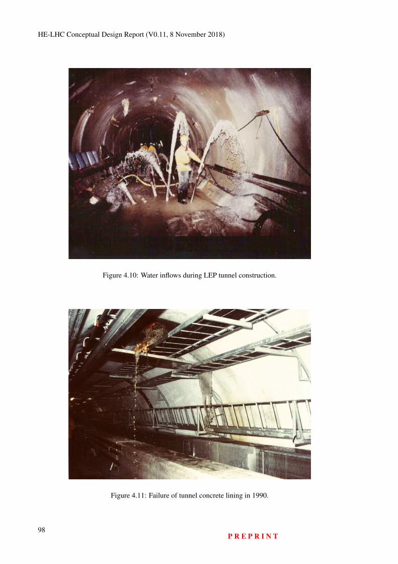
HE-LHC Conceptual Design Report (V0.11, 8 November 2018)
Figure 4.10: Water inflows during LEP tunnel construction.
Figure 4.11: Failure of tunnel concrete lining in 1990.
98P R E P R I N T
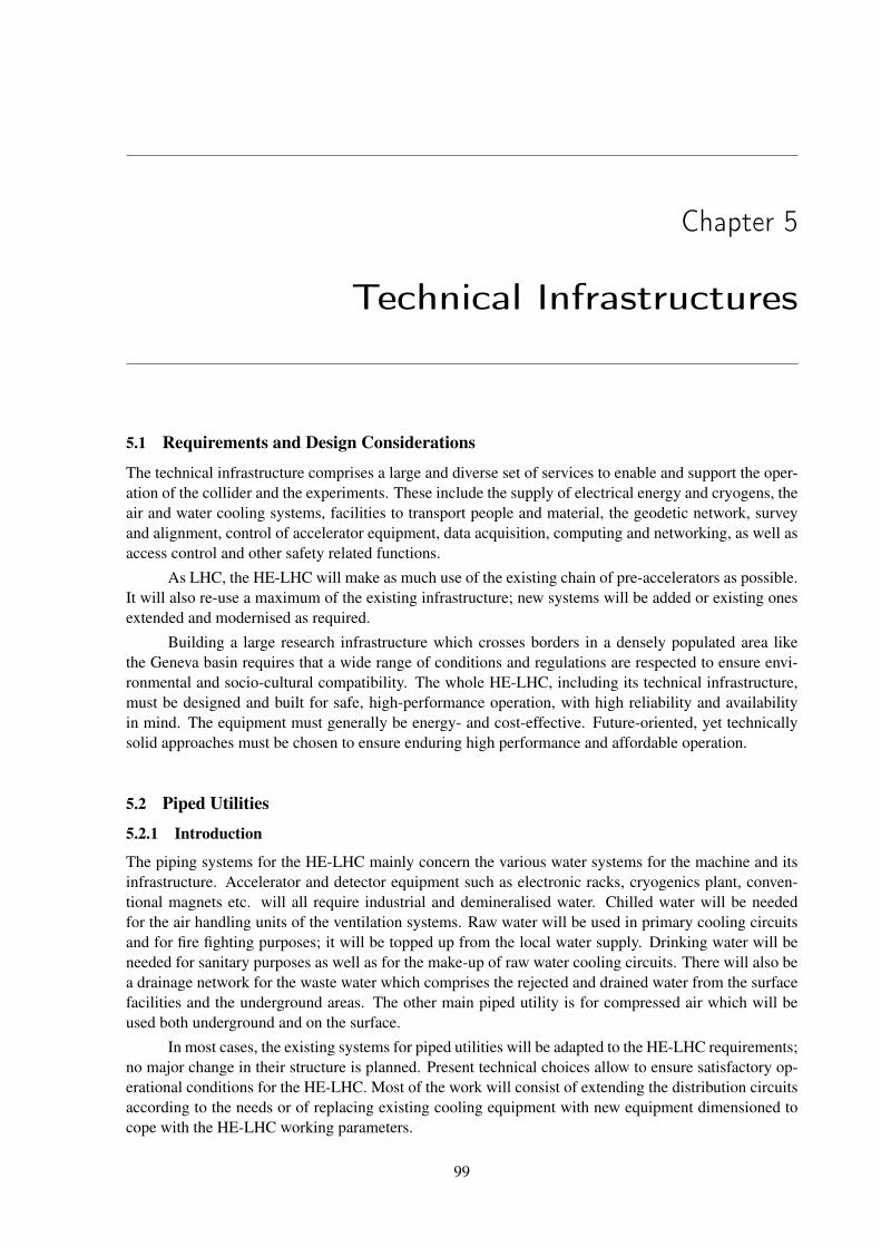
Chapter 5
Technical Infrastructures
5.1 Requirements and Design Considerations
The technical infrastructure comprises a large and diverse set of services to enable and support the oper-ation of the collider and the experiments. These include the supply of electrical energy and cryogens, theair and water cooling systems, facilities to transport people and material, the geodetic network, surveyand alignment, control of accelerator equipment, data acquisition, computing and networking, as well asaccess control and other safety related functions.
As LHC, the HE-LHC will make as much use of the existing chain of pre-accelerators as possible.It will also re-use a maximum of the existing infrastructure; new systems will be added or existing onesextended and modernised as required.
Building a large research infrastructure which crosses borders in a densely populated area likethe Geneva basin requires that a wide range of conditions and regulations are respected to ensure envi-ronmental and socio-cultural compatibility. The whole HE-LHC, including its technical infrastructure,must be designed and built for safe, high-performance operation, with high reliability and availabilityin mind. The equipment must generally be energy- and cost-effective. Future-oriented, yet technicallysolid approaches must be chosen to ensure enduring high performance and affordable operation.
5.2 Piped Utilities
5.2.1 Introduction
The piping systems for the HE-LHC mainly concern the various water systems for the machine and itsinfrastructure. Accelerator and detector equipment such as electronic racks, cryogenics plant, conven-tional magnets etc. will all require industrial and demineralised water. Chilled water will be neededfor the air handling units of the ventilation systems. Raw water will be used in primary cooling circuitsand for fire fighting purposes; it will be topped up from the local water supply. Drinking water will beneeded for sanitary purposes as well as for the make-up of raw water cooling circuits. There will also bea drainage network for the waste water which comprises the rejected and drained water from the surfacefacilities and the underground areas. The other main piped utility is for compressed air which will beused both underground and on the surface.
In most cases, the existing systems for piped utilities will be adapted to the HE-LHC requirements;no major change in their structure is planned. Present technical choices allow to ensure satisfactory op-erational conditions for the HE-LHC. Most of the work will consist of extending the distribution circuitsaccording to the needs or of replacing existing cooling equipment with new equipment dimensioned tocope with the HE-LHC working parameters.
99
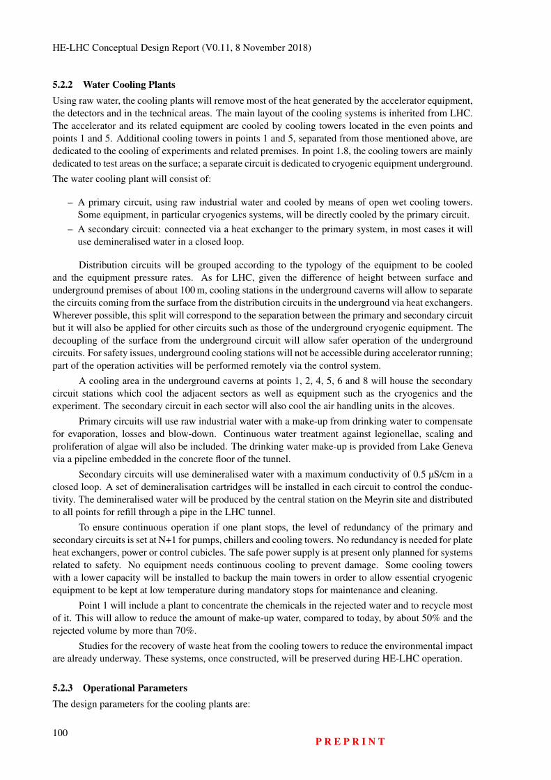
HE-LHC Conceptual Design Report (V0.11, 8 November 2018)
5.2.2 Water Cooling PlantsUsing raw water, the cooling plants will remove most of the heat generated by the accelerator equipment,the detectors and in the technical areas. The main layout of the cooling systems is inherited from LHC.The accelerator and its related equipment are cooled by cooling towers located in the even points andpoints 1 and 5. Additional cooling towers in points 1 and 5, separated from those mentioned above, arededicated to the cooling of experiments and related premises. In point 1.8, the cooling towers are mainlydedicated to test areas on the surface; a separate circuit is dedicated to cryogenic equipment underground.
The water cooling plant will consist of:
– A primary circuit, using raw industrial water and cooled by means of open wet cooling towers.Some equipment, in particular cryogenics systems, will be directly cooled by the primary circuit.
– A secondary circuit: connected via a heat exchanger to the primary system, in most cases it willuse demineralised water in a closed loop.
Distribution circuits will be grouped according to the typology of the equipment to be cooledand the equipment pressure rates. As for LHC, given the difference of height between surface andunderground premises of about 100 m, cooling stations in the underground caverns will allow to separatethe circuits coming from the surface from the distribution circuits in the underground via heat exchangers.Wherever possible, this split will correspond to the separation between the primary and secondary circuitbut it will also be applied for other circuits such as those of the underground cryogenic equipment. Thedecoupling of the surface from the underground circuit will allow safer operation of the undergroundcircuits. For safety issues, underground cooling stations will not be accessible during accelerator running;part of the operation activities will be performed remotely via the control system.
A cooling area in the underground caverns at points 1, 2, 4, 5, 6 and 8 will house the secondarycircuit stations which cool the adjacent sectors as well as equipment such as the cryogenics and theexperiment. The secondary circuit in each sector will also cool the air handling units in the alcoves.
Primary circuits will use raw industrial water with a make-up from drinking water to compensatefor evaporation, losses and blow-down. Continuous water treatment against legionellae, scaling andproliferation of algae will also be included. The drinking water make-up is provided from Lake Genevavia a pipeline embedded in the concrete floor of the tunnel.
Secondary circuits will use demineralised water with a maximum conductivity of 0.5 µS/cm in aclosed loop. A set of demineralisation cartridges will be installed in each circuit to control the conduc-tivity. The demineralised water will be produced by the central station on the Meyrin site and distributedto all points for refill through a pipe in the LHC tunnel.
To ensure continuous operation if one plant stops, the level of redundancy of the primary andsecondary circuits is set at N+1 for pumps, chillers and cooling towers. No redundancy is needed for plateheat exchangers, power or control cubicles. The safe power supply is at present only planned for systemsrelated to safety. No equipment needs continuous cooling to prevent damage. Some cooling towerswith a lower capacity will be installed to backup the main towers in order to allow essential cryogenicequipment to be kept at low temperature during mandatory stops for maintenance and cleaning.
Point 1 will include a plant to concentrate the chemicals in the rejected water and to recycle mostof it. This will allow to reduce the amount of make-up water, compared to today, by about 50% and therejected volume by more than 70%.
Studies for the recovery of waste heat from the cooling towers to reduce the environmental impactare already underway. These systems, once constructed, will be preserved during HE-LHC operation.
5.2.3 Operational ParametersThe design parameters for the cooling plants are:
100P R E P R I N T
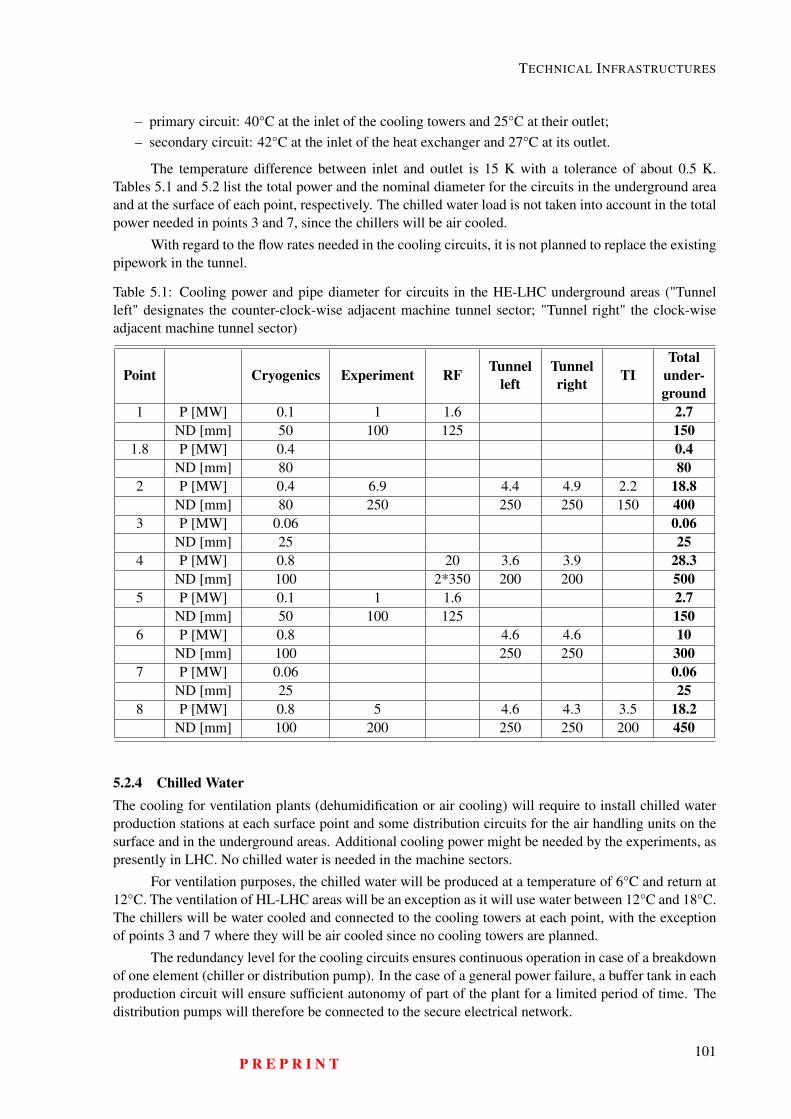
TECHNICAL INFRASTRUCTURES
– primary circuit: 40°C at the inlet of the cooling towers and 25°C at their outlet;– secondary circuit: 42°C at the inlet of the heat exchanger and 27°C at its outlet.
The temperature difference between inlet and outlet is 15 K with a tolerance of about 0.5 K.Tables 5.1 and 5.2 list the total power and the nominal diameter for the circuits in the underground areaand at the surface of each point, respectively. The chilled water load is not taken into account in the totalpower needed in points 3 and 7, since the chillers will be air cooled.
With regard to the flow rates needed in the cooling circuits, it is not planned to replace the existingpipework in the tunnel.
Table 5.1: Cooling power and pipe diameter for circuits in the HE-LHC underground areas ("Tunnelleft" designates the counter-clock-wise adjacent machine tunnel sector; "Tunnel right" the clock-wiseadjacent machine tunnel sector)
Point Cryogenics Experiment RF Tunnelleft
Tunnelright TI
Totalunder-ground
1 P [MW] 0.1 1 1.6 2.7ND [mm] 50 100 125 150
1.8 P [MW] 0.4 0.4ND [mm] 80 80
2 P [MW] 0.4 6.9 4.4 4.9 2.2 18.8ND [mm] 80 250 250 250 150 400
3 P [MW] 0.06 0.06ND [mm] 25 25
4 P [MW] 0.8 20 3.6 3.9 28.3ND [mm] 100 2*350 200 200 500
5 P [MW] 0.1 1 1.6 2.7ND [mm] 50 100 125 150
6 P [MW] 0.8 4.6 4.6 10ND [mm] 100 250 250 300
7 P [MW] 0.06 0.06ND [mm] 25 25
8 P [MW] 0.8 5 4.6 4.3 3.5 18.2ND [mm] 100 200 250 250 200 450
5.2.4 Chilled WaterThe cooling for ventilation plants (dehumidification or air cooling) will require to install chilled waterproduction stations at each surface point and some distribution circuits for the air handling units on thesurface and in the underground areas. Additional cooling power might be needed by the experiments, aspresently in LHC. No chilled water is needed in the machine sectors.
For ventilation purposes, the chilled water will be produced at a temperature of 6°C and return at12°C. The ventilation of HL-LHC areas will be an exception as it will use water between 12°C and 18°C.The chillers will be water cooled and connected to the cooling towers at each point, with the exceptionof points 3 and 7 where they will be air cooled since no cooling towers are planned.
The redundancy level for the cooling circuits ensures continuous operation in case of a breakdownof one element (chiller or distribution pump). In the case of a general power failure, a buffer tank in eachproduction circuit will ensure sufficient autonomy of part of the plant for a limited period of time. Thedistribution pumps will therefore be connected to the secure electrical network.
P R E P R I N T101
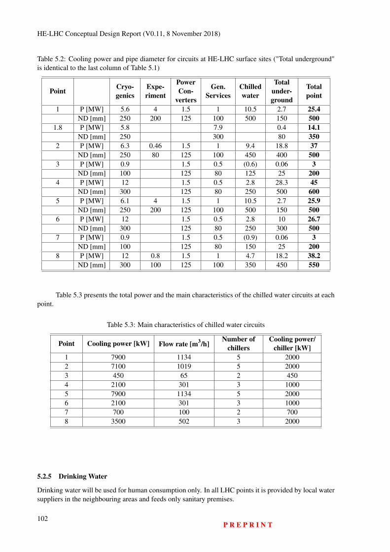
HE-LHC Conceptual Design Report (V0.11, 8 November 2018)
Table 5.2: Cooling power and pipe diameter for circuits at HE-LHC surface sites ("Total underground"is identical to the last column of Table 5.1)
Point Cryo-genics
Expe-riment
PowerCon-
verters
Gen.Services
Chilledwater
Totalunder-ground
Totalpoint
1 P [MW] 5.6 4 1.5 1 10.5 2.7 25.4ND [mm] 250 200 125 100 500 150 500
1.8 P [MW] 5.8 7.9 0.4 14.1ND [mm] 250 300 80 350
2 P [MW] 6.3 0.46 1.5 1 9.4 18.8 37ND [mm] 250 80 125 100 450 400 500
3 P [MW] 0.9 1.5 0.5 (0.6) 0.06 3ND [mm] 100 125 80 125 25 200
4 P [MW] 12 1.5 0.5 2.8 28.3 45ND [mm] 300 125 80 250 500 600
5 P [MW] 6.1 4 1.5 1 10.5 2.7 25.9ND [mm] 250 200 125 100 500 150 500
6 P [MW] 12 1.5 0.5 2.8 10 26.7ND [mm] 300 125 80 250 300 500
7 P [MW] 0.9 1.5 0.5 (0.9) 0.06 3ND [mm] 100 125 80 150 25 200
8 P [MW] 12 0.8 1.5 1 4.7 18.2 38.2ND [mm] 300 100 125 100 350 450 550
Table 5.3 presents the total power and the main characteristics of the chilled water circuits at eachpoint.
Table 5.3: Main characteristics of chilled water circuits
Point Cooling power [kW] Flow rate [m3/h]Number of
chillersCooling power/
chiller [kW]1 7900 1134 5 20002 7100 1019 5 20003 450 65 2 4504 2100 301 3 10005 7900 1134 5 20006 2100 301 3 10007 700 100 2 7008 3500 502 3 2000
5.2.5 Drinking Water
Drinking water will be used for human consumption only. In all LHC points it is provided by local watersuppliers in the neighbouring areas and feeds only sanitary premises.
102P R E P R I N T
TECHNICAL INFRASTRUCTURES
5.2.6 Raw Water
The raw water is used for the make-up of cooling towers. Its quality is similar to that of drinking water,however it cannot be considered as such and therefore it cannot be used for human consumption. Itcirculates in a non-drinking water circuit. The raw water is pumped by a dedicated pumping stationlocated in point 1 and supplied to the different points via two half-loops placed in the concrete floor slabof the tunnel. The half-loops are connected together by means of a valve between point 4 and point 5in order to allow water supply from two directions. Isolation valves allow to isolate part of the networkwithout affecting the availability of water in the remaining part. Dedicated pumps in the undergroundcaverns at each point raise the water to the surface.
5.2.7 Fire Fighting Network
The existing fire fighting network in all LHC points is fed by the raw water half-loops with a dedicatedbranch in the underground caverns of each point. At present, the underground service and experimentcaverns are equipped with fire hoses as well as the part of the tunnel close to each point. No fire fightingpipework exists in the middle of each sector. If it is needed for HE-LHC, the existing pipework will beextended accordingly.
Surface premises will be protected by a hydrant network and by dedicated water hoses inside thebuildings where necessary. Most of the surface hydrants are fed by the raw water circuit. One of them isfed by the local water network in order to ensure a minimum availability if the raw water loop fails. Anadditional volume of water is available from the cooling towers basins, where they exist. The fire brigadecan connect flexible hoses to them via Storz connections.
If the water pumping station for LHC stops, the fire fighting requirements will be met by thedrinking water station dedicated to the Meyrin and Prevessin sites acting as a backup. All stations are onthe secure electrical network which compensates for power supply failures.
5.2.8 Reject Water
Two separate pump systems to lift sewage are installed underground at each point. They are connectedto the local drainage network of the point. Retention basins are located in point 7 and 8 to separatenatural hydrocarbons which have infiltrated the tunnel before release into the local network. The clearwater reject network, which also takes the blow-down from the cooling towers, is composed of two half-loops, parallel to the raw water ones, embedded in the concrete floor of the tunnel. Water is pumped tothe surface of point 1 from where it is rejected in the local clear water drainage. In order to decreasethe volume of discharged water, a specific treatment plant will be implemented at point 1 for all rejectedwater; the residue will then be discharged in the sewage. All underground equipment (tunnel and caverns)must be redundant in order to avoid affecting operation in case of breakdown. Alarms for "high level"and "level too high" will be implemented in all basins.
In sector 3-4, a continuous arrival in the tunnel of water mixed with sand from an undergroundwater conduit has required the installation of a dedicated system in point 3.2 of LHC. A pit is equippedwith a set of pumps able to continuously lift the mix of sand and water to the surface. The pit is dividedinto two separate volumes in order to allow maintenance in one of them without stopping the evacuationof water. The redundancy level of the pumps in each volume of the pit is 3N and the power can beprovided by 3 different sources to avoid any stop. A decantation basin on the surface allows to separatewater from the sand before releasing it into the nearby stream.
The main parameters (e.g. temperature, pH) of the rejected water are monitored before release.
P R E P R I N T103
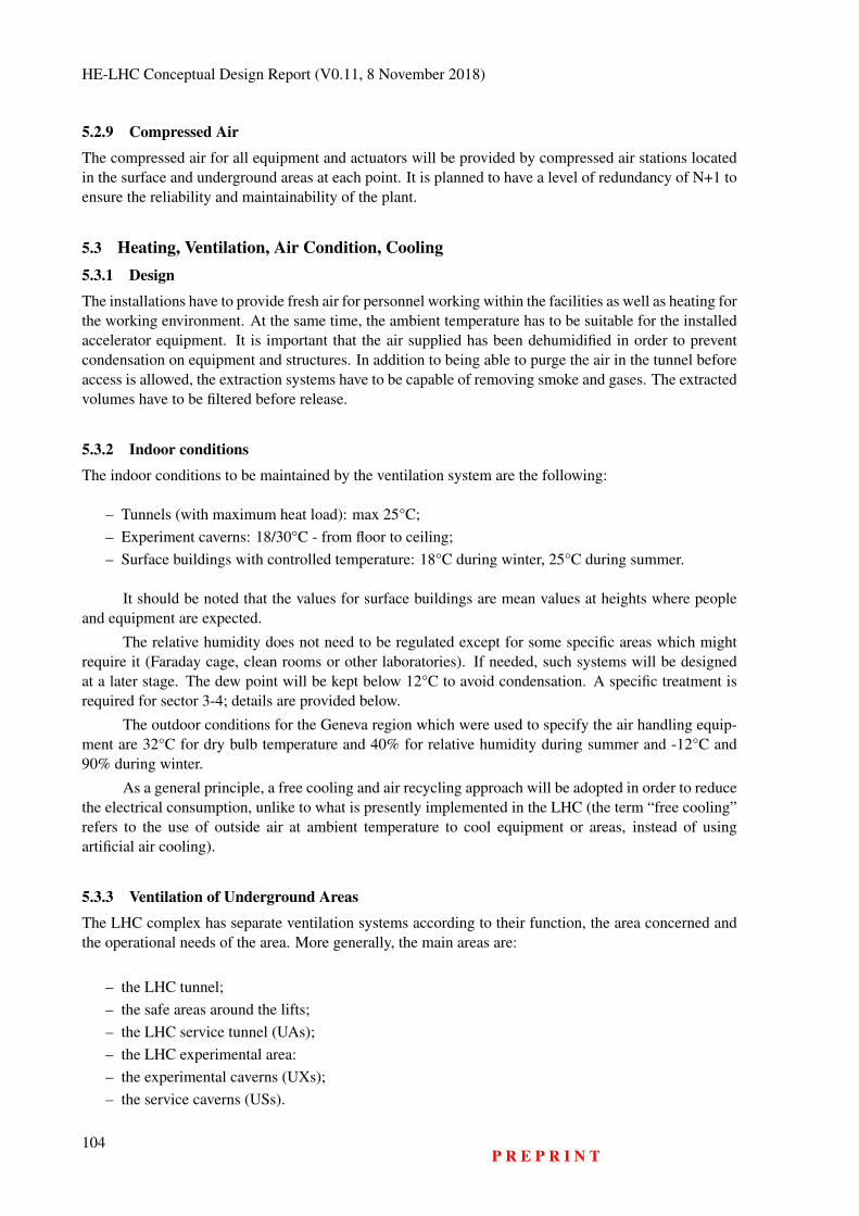
HE-LHC Conceptual Design Report (V0.11, 8 November 2018)
5.2.9 Compressed Air
The compressed air for all equipment and actuators will be provided by compressed air stations locatedin the surface and underground areas at each point. It is planned to have a level of redundancy of N+1 toensure the reliability and maintainability of the plant.
5.3 Heating, Ventilation, Air Condition, Cooling5.3.1 Design
The installations have to provide fresh air for personnel working within the facilities as well as heating forthe working environment. At the same time, the ambient temperature has to be suitable for the installedaccelerator equipment. It is important that the air supplied has been dehumidified in order to preventcondensation on equipment and structures. In addition to being able to purge the air in the tunnel beforeaccess is allowed, the extraction systems have to be capable of removing smoke and gases. The extractedvolumes have to be filtered before release.
5.3.2 Indoor conditions
The indoor conditions to be maintained by the ventilation system are the following:
– Tunnels (with maximum heat load): max 25°C;– Experiment caverns: 18/30°C - from floor to ceiling;– Surface buildings with controlled temperature: 18°C during winter, 25°C during summer.
It should be noted that the values for surface buildings are mean values at heights where peopleand equipment are expected.
The relative humidity does not need to be regulated except for some specific areas which mightrequire it (Faraday cage, clean rooms or other laboratories). If needed, such systems will be designedat a later stage. The dew point will be kept below 12°C to avoid condensation. A specific treatment isrequired for sector 3-4; details are provided below.
The outdoor conditions for the Geneva region which were used to specify the air handling equip-ment are 32°C for dry bulb temperature and 40% for relative humidity during summer and -12°C and90% during winter.
As a general principle, a free cooling and air recycling approach will be adopted in order to reducethe electrical consumption, unlike to what is presently implemented in the LHC (the term “free cooling”refers to the use of outside air at ambient temperature to cool equipment or areas, instead of usingartificial air cooling).
5.3.3 Ventilation of Underground Areas
The LHC complex has separate ventilation systems according to their function, the area concerned andthe operational needs of the area. More generally, the main areas are:
– the LHC tunnel;– the safe areas around the lifts;– the LHC service tunnel (UAs);– the LHC experimental area:– the experimental caverns (UXs);– the service caverns (USs).
104P R E P R I N T
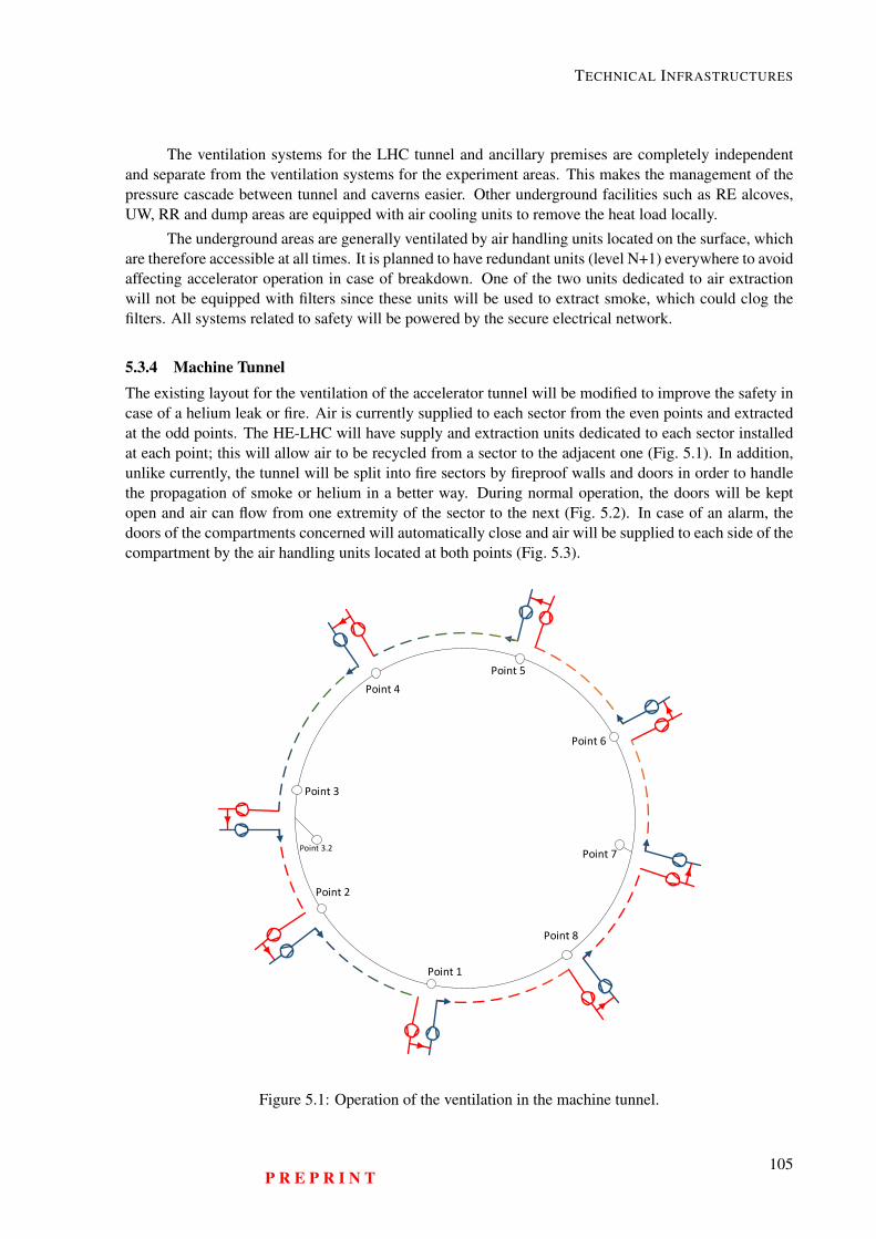
TECHNICAL INFRASTRUCTURES
The ventilation systems for the LHC tunnel and ancillary premises are completely independentand separate from the ventilation systems for the experiment areas. This makes the management of thepressure cascade between tunnel and caverns easier. Other underground facilities such as RE alcoves,UW, RR and dump areas are equipped with air cooling units to remove the heat load locally.
The underground areas are generally ventilated by air handling units located on the surface, whichare therefore accessible at all times. It is planned to have redundant units (level N+1) everywhere to avoidaffecting accelerator operation in case of breakdown. One of the two units dedicated to air extractionwill not be equipped with filters since these units will be used to extract smoke, which could clog thefilters. All systems related to safety will be powered by the secure electrical network.
5.3.4 Machine TunnelThe existing layout for the ventilation of the accelerator tunnel will be modified to improve the safety incase of a helium leak or fire. Air is currently supplied to each sector from the even points and extractedat the odd points. The HE-LHC will have supply and extraction units dedicated to each sector installedat each point; this will allow air to be recycled from a sector to the adjacent one (Fig. 5.1). In addition,unlike currently, the tunnel will be split into fire sectors by fireproof walls and doors in order to handlethe propagation of smoke or helium in a better way. During normal operation, the doors will be keptopen and air can flow from one extremity of the sector to the next (Fig. 5.2). In case of an alarm, thedoors of the compartments concerned will automatically close and air will be supplied to each side of thecompartment by the air handling units located at both points (Fig. 5.3).
Point 5
Point 4
Point 3
Point 2
Point 1
Point 8
Point 7
Point 6
Point 3.2
Figure 5.1: Operation of the ventilation in the machine tunnel.
P R E P R I N T105
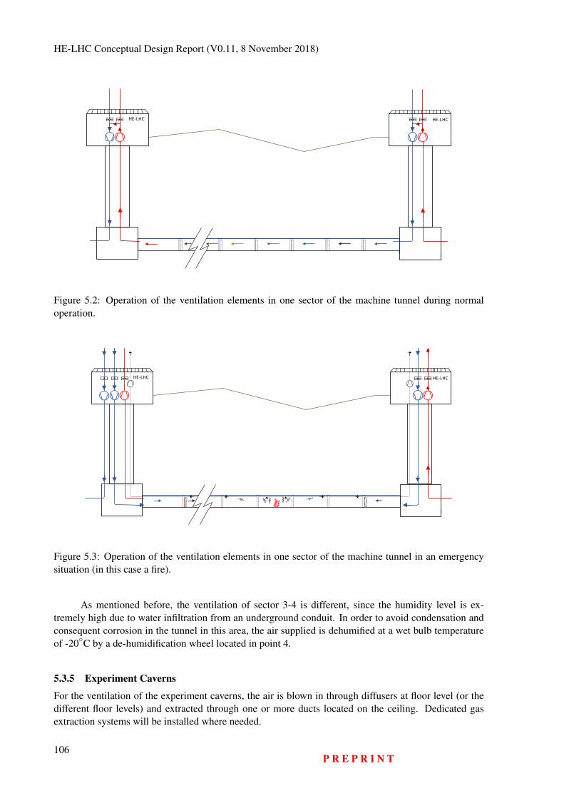
HE-LHC Conceptual Design Report (V0.11, 8 November 2018)
HE-LHCHE-LHC
Figure 5.2: Operation of the ventilation elements in one sector of the machine tunnel during normaloperation.
HE-LHCHE-LHC
Figure 5.3: Operation of the ventilation elements in one sector of the machine tunnel in an emergencysituation (in this case a fire).
As mentioned before, the ventilation of sector 3-4 is different, since the humidity level is ex-tremely high due to water infiltration from an underground conduit. In order to avoid condensation andconsequent corrosion in the tunnel in this area, the air supplied is dehumified at a wet bulb temperatureof -20C by a de-humidification wheel located in point 4.
5.3.5 Experiment Caverns
For the ventilation of the experiment caverns, the air is blown in through diffusers at floor level (or thedifferent floor levels) and extracted through one or more ducts located on the ceiling. Dedicated gasextraction systems will be installed where needed.
106P R E P R I N T
TECHNICAL INFRASTRUCTURES
5.3.6 Other Areas
Local air handling units will be added in areas housing equipment with particularly high heat dissipation.These units will be fitted with coils cooled by chilled water produced on the surface.
5.3.7 Operating Modes
It is planned to have different modes for the ventilation systems depending on the machine operatingconditions; these are presented in Table 5.4. All motors for ventilators will be equipped with variablespeed drives in order to adjust the flow rates, to adapt the working conditions to the operational needsand to achieve the dynamic confinement between adjacent areas, where requested.
Table 5.4: Operating modes and conditions for ventilation systems
Mode ConditionsRun No access, accelerators running and equipment powered, full air recycling
Shutdown Open access, accelerator stopped, maintenance interventions, fresh air/partial recyclingPurge Where needed, before allowing access to personnel, accelerator stopped fresh air.
5.3.8 Working Parameters
Table 5.5 shows the main ventilation parameters of an HE-LHC tunnel sector. The parameters of theventilation plants for the underground points are presented in Table 5.6. In areas where a supply and anextraction system are installed, the air can be recycled according to the operating mode.
Table 5.5: Working parameters for the ventilation of one machine tunnel sector
Parameter Flow rate [m3/h] Air speed [m/s]Air flow in run and shutdown modes 18000 0.7 - 1
Air flow in purge mode 64000 2 - 3
Table 5.6: Working parameters of air handling units for underground areas
Underground area Nominal flowrate [m3/h]
Nominal ductdiameter
[mm]Air recycling
Point 1 Experiment cavern 30000 1450 YesPoint 2 Experiment cavern 45000 1500 Not at presentPoint 4 Cavern 45000 1500 Not at presentPoint 5 Experiment cavern 22500 1400 YesPoint 6 Cavern 45000 1500 Not at presentPoint 8 Experiment cavern 22500 1500 Not at presentShaft and safe area pressurisation(PM, PX)
8000 - 12000 600 - 700 No
Fresh air to service caverns at acceler-ator points (US, UL and UA)
22500 900 No
The level of filtering of the exhaust air before its release to the atmosphere will be mainly deter-mined by the radiation protection requirements.
P R E P R I N T107
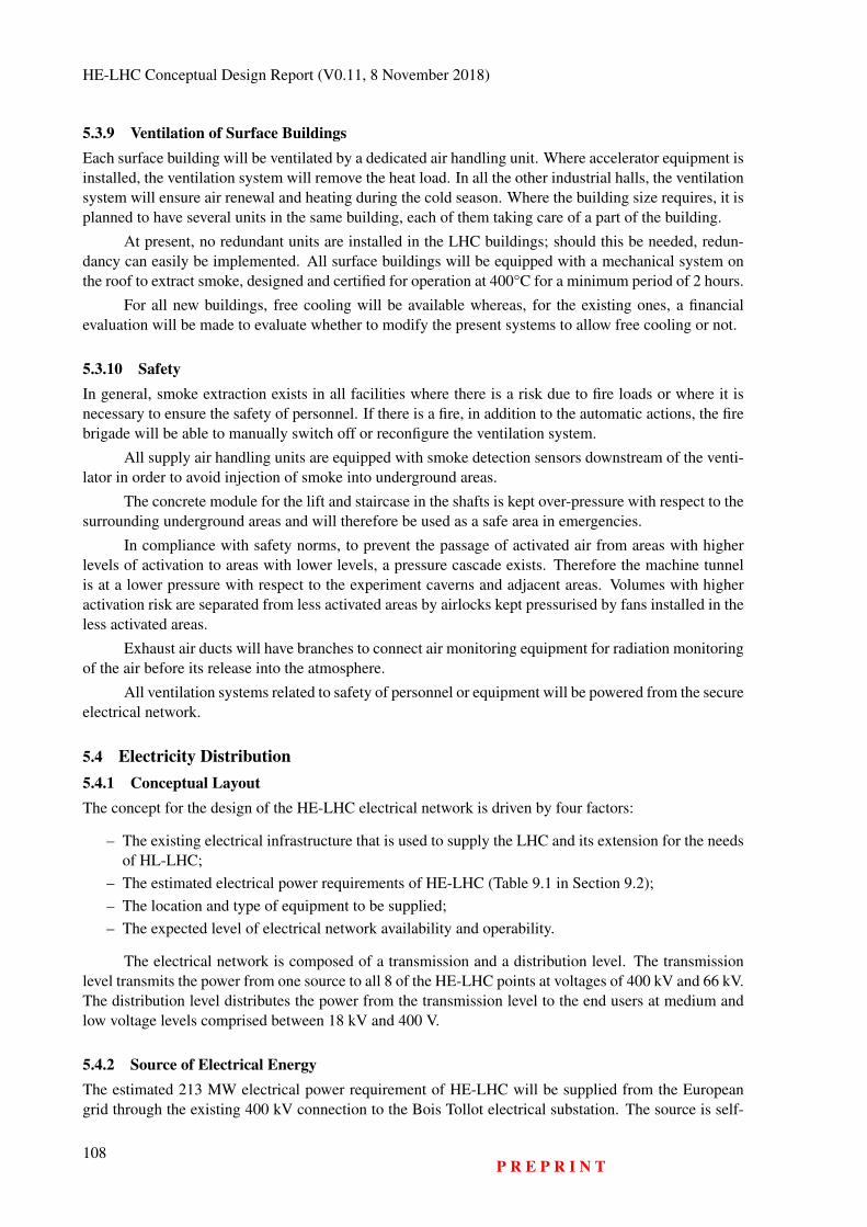
HE-LHC Conceptual Design Report (V0.11, 8 November 2018)
5.3.9 Ventilation of Surface BuildingsEach surface building will be ventilated by a dedicated air handling unit. Where accelerator equipment isinstalled, the ventilation system will remove the heat load. In all the other industrial halls, the ventilationsystem will ensure air renewal and heating during the cold season. Where the building size requires, it isplanned to have several units in the same building, each of them taking care of a part of the building.
At present, no redundant units are installed in the LHC buildings; should this be needed, redun-dancy can easily be implemented. All surface buildings will be equipped with a mechanical system onthe roof to extract smoke, designed and certified for operation at 400°C for a minimum period of 2 hours.
For all new buildings, free cooling will be available whereas, for the existing ones, a financialevaluation will be made to evaluate whether to modify the present systems to allow free cooling or not.
5.3.10 SafetyIn general, smoke extraction exists in all facilities where there is a risk due to fire loads or where it isnecessary to ensure the safety of personnel. If there is a fire, in addition to the automatic actions, the firebrigade will be able to manually switch off or reconfigure the ventilation system.
All supply air handling units are equipped with smoke detection sensors downstream of the venti-lator in order to avoid injection of smoke into underground areas.
The concrete module for the lift and staircase in the shafts is kept over-pressure with respect to thesurrounding underground areas and will therefore be used as a safe area in emergencies.
In compliance with safety norms, to prevent the passage of activated air from areas with higherlevels of activation to areas with lower levels, a pressure cascade exists. Therefore the machine tunnelis at a lower pressure with respect to the experiment caverns and adjacent areas. Volumes with higheractivation risk are separated from less activated areas by airlocks kept pressurised by fans installed in theless activated areas.
Exhaust air ducts will have branches to connect air monitoring equipment for radiation monitoringof the air before its release into the atmosphere.
All ventilation systems related to safety of personnel or equipment will be powered from the secureelectrical network.
5.4 Electricity Distribution5.4.1 Conceptual LayoutThe concept for the design of the HE-LHC electrical network is driven by four factors:
– The existing electrical infrastructure that is used to supply the LHC and its extension for the needsof HL-LHC;
– The estimated electrical power requirements of HE-LHC (Table 9.1 in Section 9.2);– The location and type of equipment to be supplied;– The expected level of electrical network availability and operability.
The electrical network is composed of a transmission and a distribution level. The transmissionlevel transmits the power from one source to all 8 of the HE-LHC points at voltages of 400 kV and 66 kV.The distribution level distributes the power from the transmission level to the end users at medium andlow voltage levels comprised between 18 kV and 400 V.
5.4.2 Source of Electrical EnergyThe estimated 213 MW electrical power requirement of HE-LHC will be supplied from the Europeangrid through the existing 400 kV connection to the Bois Tollot electrical substation. The source is self-
108P R E P R I N T
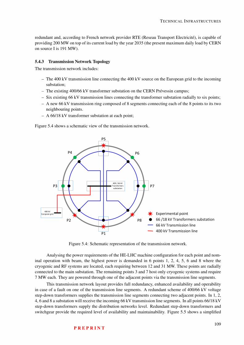
TECHNICAL INFRASTRUCTURES
redundant and, according to French network provider RTE (Reseau Transport Electricité), is capable ofproviding 200 MW on top of its current load by the year 2035 (the present maximum daily load by CERNon source I is 191 MW).
5.4.3 Transmission Network TopologyThe transmission network includes:
– The 400 kV transmission line connecting the 400 kV source on the European grid to the incomingsubstation;
– The existing 400/66 kV transformer substation on the CERN Prévessin campus;– Six existing 66 kV transmission lines connecting the transformer substation radially to six points;– A new 66 kV transmission ring composed of 8 segments connecting each of the 8 points to its two
neighbouring points.– A 66/18 kV transformer substation at each point;
Figure 5.4 shows a schematic view of the transmission network.
Experimental point
P5
P4 P6
P7P3
P2 P8
P1
400 / 66 kV
Transformers
substation
400 kV
European grid
66 /18 kV Transformers substation
66 kV Transmission line
400 kV Transmission line
Figure 5.4: Schematic representation of the transmission network.
Analysing the power requirements of the HE-LHC machine configuration for each point and nom-inal operation with beam, the highest power is demanded in 6 points 1, 2, 4, 5, 6 and 8 where thecryogenic and RF systems are located, each requiring between 12 and 31 MW. These points are radiallyconnected to the main substation. The remaining points 3 and 7 host only cryogenic systems and require7 MW each. They are powered through one of the adjacent points via the transmission line segments.
This transmission network layout provides full redundancy, enhanced availability and operabilityin case of a fault on one of the transmission line segments. A redundant scheme of 400/66 kV voltagestep-down transformers supplies the transmission line segments connecting two adjacent points. In 1, 2,4, 6 and 8 a substation will receive the incoming 66 kV transmission line segments. In all points 66/18 kVstep-down transformers supply the distribution networks level. Redundant step-down transformers andswitchgear provide the required level of availability and maintainability. Figure 5.5 shows a simplified
P R E P R I N T109
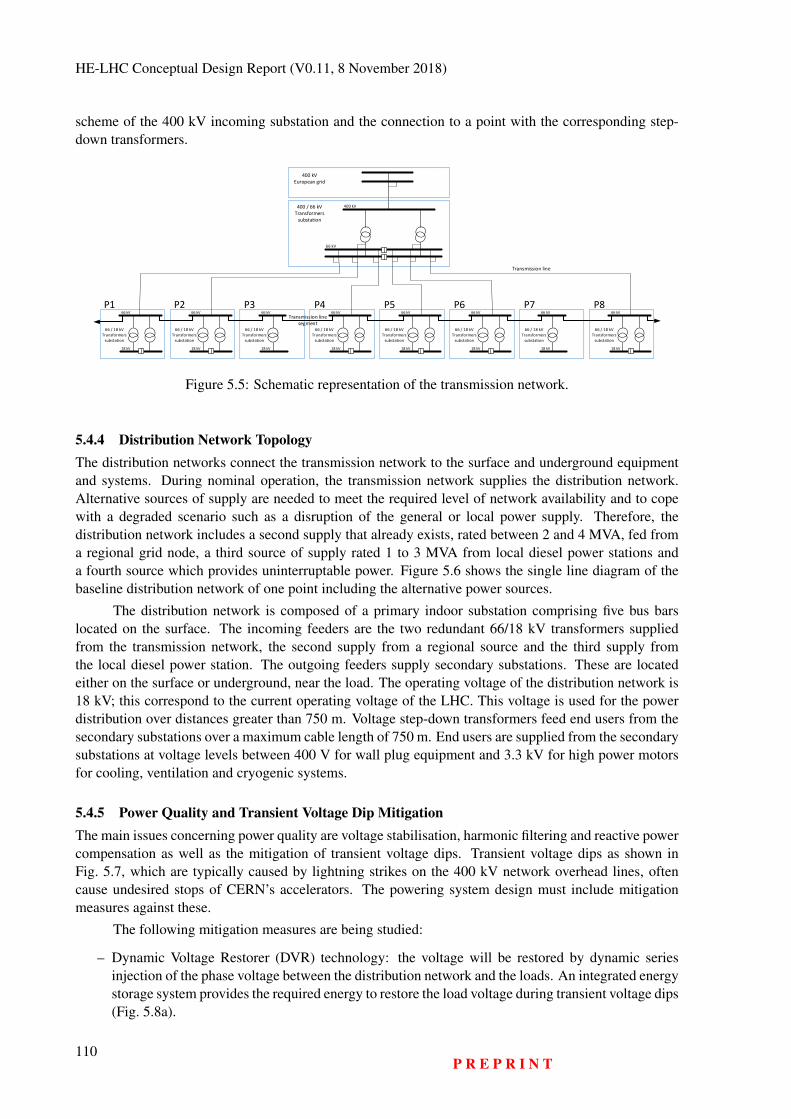
HE-LHC Conceptual Design Report (V0.11, 8 November 2018)
scheme of the 400 kV incoming substation and the connection to a point with the corresponding step-down transformers.
400 kV
European grid
400 / 66 kV
Transformers
substation
Transmission line
Transmission line
segment
66 kV
66 / 18 kV
Transformers
substation
66 kV
18 kV
66 / 18 kV
Transformers
substation
66 kV
18 kV
66 / 18 kV
Transformers
substation
66 kV
18 kV
66 / 18 kV
Transformers
substation
66 kV
18 kV
66 / 18 kV
Transformers
substation
66 kV
18 kV
66 / 18 kV
Transformers
substation
66 kV
18 kV
66 / 18 kV
Transformers
substation
66 kV
18 kV
P1 P2 P3 P4 P5 P6 P7 P8
66 / 18 kV
Transformers
substation
66 kV
18 kV
400 kV
Figure 5.5: Schematic representation of the transmission network.
5.4.4 Distribution Network TopologyThe distribution networks connect the transmission network to the surface and underground equipmentand systems. During nominal operation, the transmission network supplies the distribution network.Alternative sources of supply are needed to meet the required level of network availability and to copewith a degraded scenario such as a disruption of the general or local power supply. Therefore, thedistribution network includes a second supply that already exists, rated between 2 and 4 MVA, fed froma regional grid node, a third source of supply rated 1 to 3 MVA from local diesel power stations anda fourth source which provides uninterruptable power. Figure 5.6 shows the single line diagram of thebaseline distribution network of one point including the alternative power sources.
The distribution network is composed of a primary indoor substation comprising five bus barslocated on the surface. The incoming feeders are the two redundant 66/18 kV transformers suppliedfrom the transmission network, the second supply from a regional source and the third supply fromthe local diesel power station. The outgoing feeders supply secondary substations. These are locatedeither on the surface or underground, near the load. The operating voltage of the distribution network is18 kV; this correspond to the current operating voltage of the LHC. This voltage is used for the powerdistribution over distances greater than 750 m. Voltage step-down transformers feed end users from thesecondary substations over a maximum cable length of 750 m. End users are supplied from the secondarysubstations at voltage levels between 400 V for wall plug equipment and 3.3 kV for high power motorsfor cooling, ventilation and cryogenic systems.
5.4.5 Power Quality and Transient Voltage Dip MitigationThe main issues concerning power quality are voltage stabilisation, harmonic filtering and reactive powercompensation as well as the mitigation of transient voltage dips. Transient voltage dips as shown inFig. 5.7, which are typically caused by lightning strikes on the 400 kV network overhead lines, oftencause undesired stops of CERN’s accelerators. The powering system design must include mitigationmeasures against these.
The following mitigation measures are being studied:
– Dynamic Voltage Restorer (DVR) technology: the voltage will be restored by dynamic seriesinjection of the phase voltage between the distribution network and the loads. An integrated energystorage system provides the required energy to restore the load voltage during transient voltage dips(Fig. 5.8a).
110P R E P R I N T
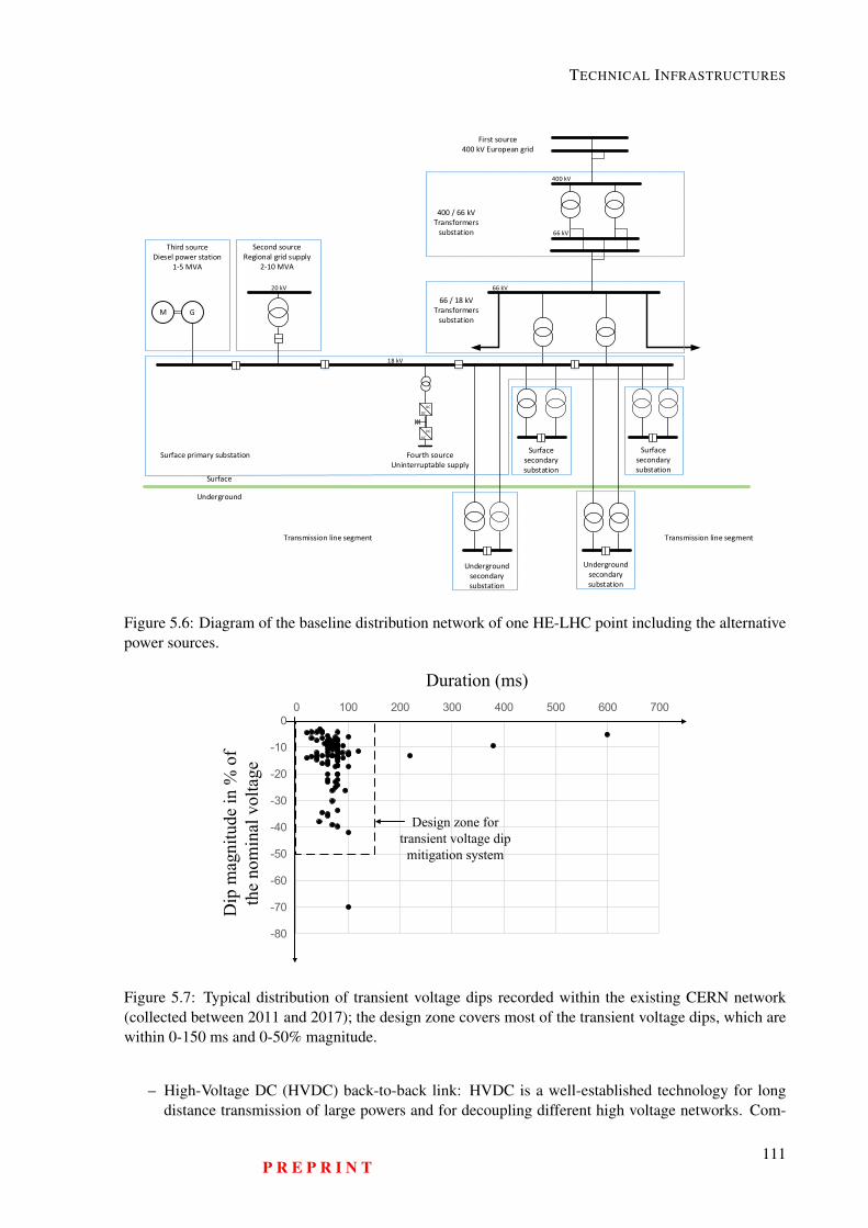
TECHNICAL INFRASTRUCTURES
Surface
secondary
substation
Underground
secondary
substation
Underground
secondary
substation
Surface
secondary
substation
Second source
Regional grid supply
2-10 MVA
Third source
Diesel power station
1-5 MVA
M G
AC
DC
AC
DC
Surface
Underground
First source
400 kV European grid
400 / 66 kV
Transformers
substation
Surface primary substation Fourth source
Uninterruptable supply
Transmission line segment Transmission line segment
66 / 18 kV
Transformers
substation
66 kV
400 kV
18 kV
20 kV
66 kV
Figure 5.6: Diagram of the baseline distribution network of one HE-LHC point including the alternativepower sources.
-80
-70
-60
-50
-40
-30
-20
-10
00 100 200 300 400 500 600 700
Duration (ms)
Dip
mag
nitu
de in
% o
f th
e no
min
al v
olta
ge
Design zone for transient voltage dip
mitigation system
Figure 5.7: Typical distribution of transient voltage dips recorded within the existing CERN network(collected between 2011 and 2017); the design zone covers most of the transient voltage dips, which arewithin 0-150 ms and 0-50% magnitude.
– High-Voltage DC (HVDC) back-to-back link: HVDC is a well-established technology for longdistance transmission of large powers and for decoupling different high voltage networks. Com-
P R E P R I N T111
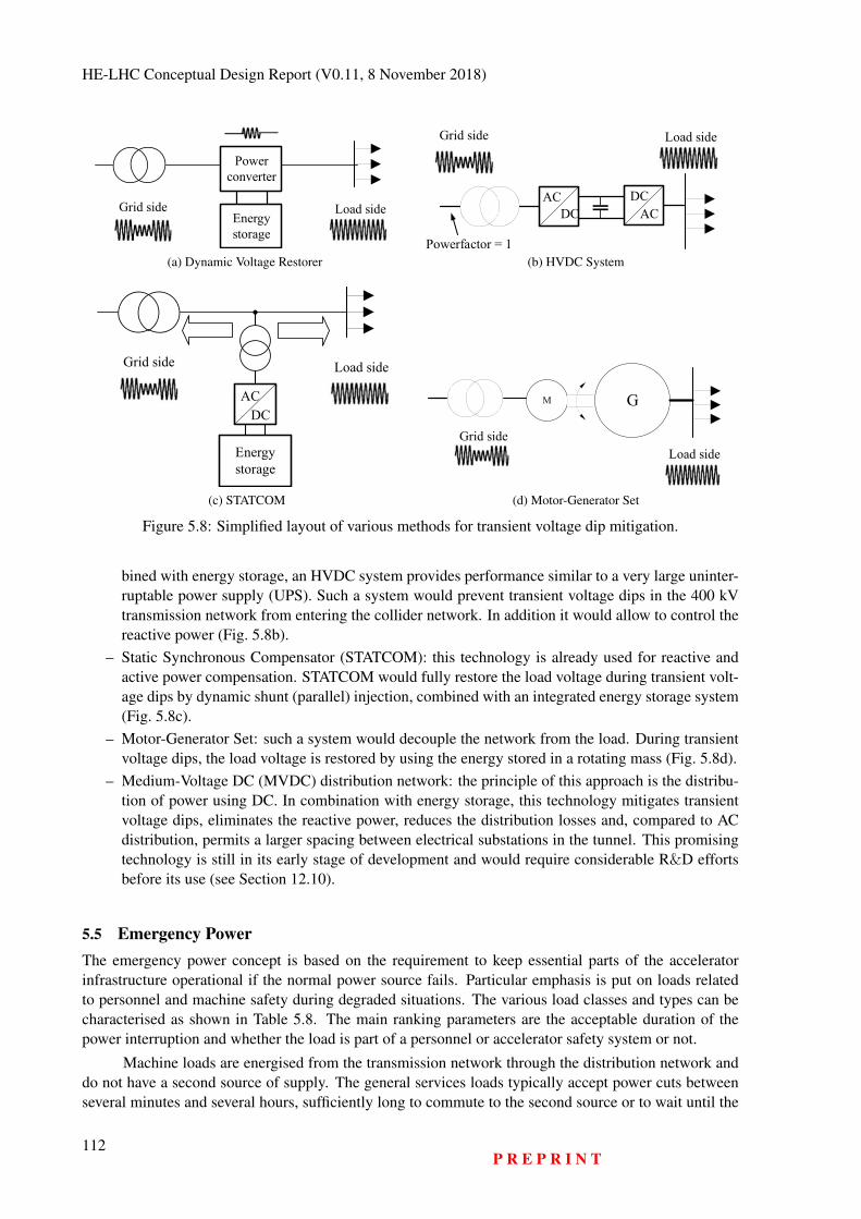
HE-LHC Conceptual Design Report (V0.11, 8 November 2018)
Grid side Load side
Power converter
Energy storage
(a) Dynamic Voltage Restorer
ACDC
DCAC
Powerfactor = 1
Grid side Load side
(b) HVDC System
Grid side Load side
ACDC
Energy storage
(c) STATCOM
M G
Load sideGrid side
(d) Motor-Generator Set
Figure 5.8: Simplified layout of various methods for transient voltage dip mitigation.
bined with energy storage, an HVDC system provides performance similar to a very large uninter-ruptable power supply (UPS). Such a system would prevent transient voltage dips in the 400 kVtransmission network from entering the collider network. In addition it would allow to control thereactive power (Fig. 5.8b).
– Static Synchronous Compensator (STATCOM): this technology is already used for reactive andactive power compensation. STATCOM would fully restore the load voltage during transient volt-age dips by dynamic shunt (parallel) injection, combined with an integrated energy storage system(Fig. 5.8c).
– Motor-Generator Set: such a system would decouple the network from the load. During transientvoltage dips, the load voltage is restored by using the energy stored in a rotating mass (Fig. 5.8d).
– Medium-Voltage DC (MVDC) distribution network: the principle of this approach is the distribu-tion of power using DC. In combination with energy storage, this technology mitigates transientvoltage dips, eliminates the reactive power, reduces the distribution losses and, compared to ACdistribution, permits a larger spacing between electrical substations in the tunnel. This promisingtechnology is still in its early stage of development and would require considerable R&D effortsbefore its use (see Section 12.10).
5.5 Emergency PowerThe emergency power concept is based on the requirement to keep essential parts of the acceleratorinfrastructure operational if the normal power source fails. Particular emphasis is put on loads relatedto personnel and machine safety during degraded situations. The various load classes and types can becharacterised as shown in Table 5.8. The main ranking parameters are the acceptable duration of thepower interruption and whether the load is part of a personnel or accelerator safety system or not.
Machine loads are energised from the transmission network through the distribution network anddo not have a second source of supply. The general services loads typically accept power cuts betweenseveral minutes and several hours, sufficiently long to commute to the second source or to wait until the
112P R E P R I N T
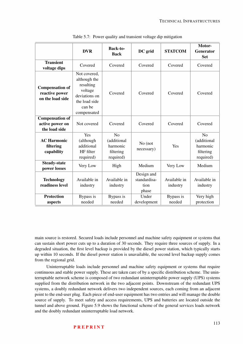
TECHNICAL INFRASTRUCTURES
Table 5.7: Power quality and transient voltage dip mitigation
DVR Back-to-Back DC grid STATCOM
Motor-Generator
SetTransient
voltage dips Covered Covered Covered Covered Covered
Compensation ofreactive poweron the load side
Not covered,although the
resultingvoltage
deviations onthe load side
can becompensated
Covered Covered Covered Covered
Compensation ofactive power on
the load sideNot covered Covered Covered Covered Covered
AC Harmonicfiltering
capability
Yes(althoughadditionalHF filterrequired)
No(additionalharmonicfilteringrequired)
No (notnecessary)
Yes
No(additionalharmonicfilteringrequired)
Steady-statepower losses Very Low High Medium Very Low Medium
Technologyreadiness level
Available inindustry
Available inindustry
Design andstandardisa-
tionphase
Available inindustry
Available inindustry
Protectionaspects
Bypass isneeded
Bypass isneeded
Underdevelopment
Bypass isneeded
Very highprotection
main source is restored. Secured loads include personnel and machine safety equipment or systems thatcan sustain short power cuts up to a duration of 30 seconds. They require three sources of supply. In adegraded situation, the first level backup is provided by the diesel power station, which typically startsup within 10 seconds. If the diesel power station is unavailable, the second level backup supply comesfrom the regional grid.
Uninterruptable loads include personnel and machine safety equipment or systems that requirecontinuous and stable power supply. These are taken care of by a specific distribution scheme. The unin-terruptable network scheme is composed of two redundant uninterruptable power supply (UPS) systemssupplied from the distribution network in the two adjacent points. Downstream of the redundant UPSsystems, a doubly redundant network delivers two independent sources, each coming from an adjacentpoint to the end-user plug. Each piece of end-user equipment has two entries and will manage the doublesource of supply. To meet safety and access requirements, UPS and batteries are located outside thetunnel and above ground. Figure 5.9 shows the functional scheme of the general services loads networkand the doubly redundant uninterruptable load network.
P R E P R I N T113
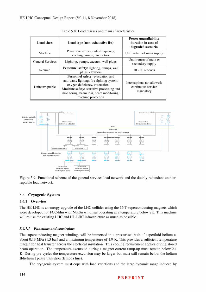
HE-LHC Conceptual Design Report (V0.11, 8 November 2018)
Table 5.8: Load classes and main characteristics
Load class Load type (non-exhaustive list)Power unavailabilityduration in case ofdegraded scenario
Machine Power converters, radio frequency,cooling pumps, fan motors Until return of main supply
General Services Lighting, pumps, vacuum, wall plugs Until return of main orsecondary supply
Secured Personnel safety: lighting, pumps, wallplugs, elevators 10 - 30 seconds
Uninterruptable
Personnel safety: evacuation andanti-panic lighting, fire-fighting system,
oxygen deficiency, evacuationMachine safety: sensitive processing andmonitoring, beam loss, beam monitoring,
machine protection
Interruptions not allowed;continuous service
mandatory
Surface
Underground
`
AC
DC
AC
DC
AC
DC
AC
DC
Main surface
distribution substation
AC
DC
AC
DC
AC
DC
AC
DC
Double source
commuting switch n
Double source
commuting switch 1
Uninterruptable load 1
Secured Load 1General services load 1
Main surface
distribution substation
Uninterruptable double
redundant network
Uninterruptable
redundant
power source
General services and secured network
Uninterruptable load n
Distribution network Distribution network18 KV18 kV
Figure 5.9: Functional scheme of the general services load network and the doubly redundant uninter-ruptable load network.
5.6 Cryogenic System5.6.1 OverviewThe HE-LHC is an energy upgrade of the LHC collider using the 16 T superconducting magnets whichwere developed for FCC-hhn with Nb3Sn windings operating at a temperature below 2K. This machinewill re-use the existing LHC and HL-LHC infrastructure as much as possible.
5.6.1.1 Functions and constraints
The superconducting magnet windings will be immersed in a pressurised bath of superfluid helium atabout 0.13 MPa (1.3 bar) and a maximum temperature of 1.9 K. This provides a sufficient temperaturemargin for heat transfer across the electrical insulation. This cooling requirement applies during storedbeam operation. The temperature excursion during a magnet current ramp-up must remain below 2.1K. During pre-cycles the temperature excursion may be larger but must still remain below the heliumII/helium I phase transition (lambda line).
The cryogenic system must cope with load variations and the large dynamic range induced by
114P R E P R I N T
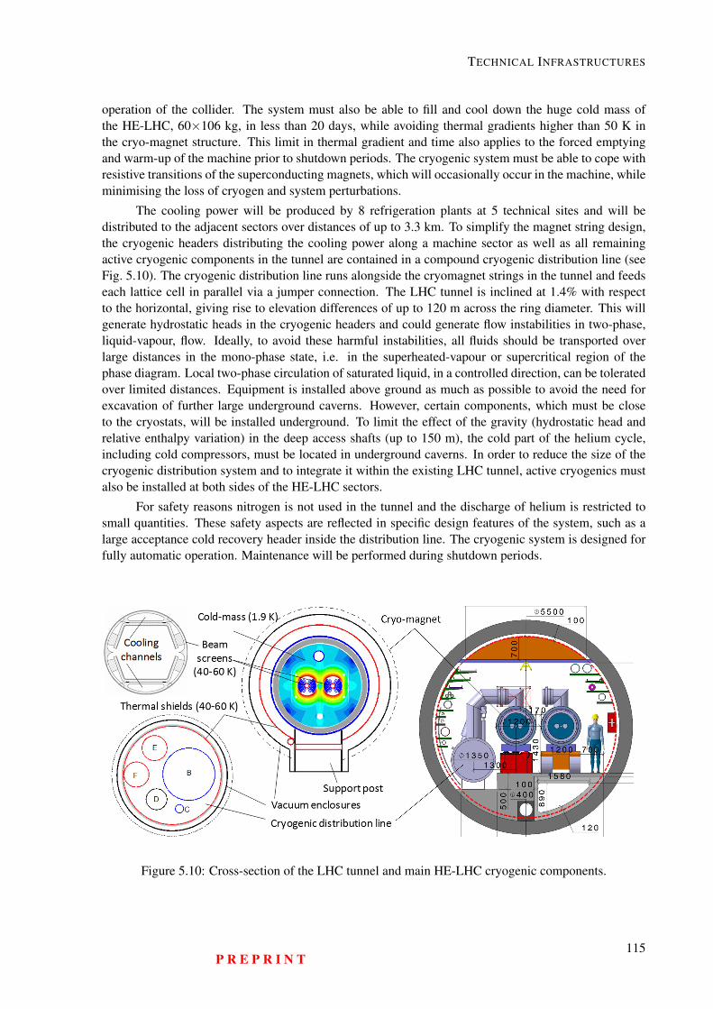
TECHNICAL INFRASTRUCTURES
operation of the collider. The system must also be able to fill and cool down the huge cold mass ofthe HE-LHC, 60×106 kg, in less than 20 days, while avoiding thermal gradients higher than 50 K inthe cryo-magnet structure. This limit in thermal gradient and time also applies to the forced emptyingand warm-up of the machine prior to shutdown periods. The cryogenic system must be able to cope withresistive transitions of the superconducting magnets, which will occasionally occur in the machine, whileminimising the loss of cryogen and system perturbations.
The cooling power will be produced by 8 refrigeration plants at 5 technical sites and will bedistributed to the adjacent sectors over distances of up to 3.3 km. To simplify the magnet string design,the cryogenic headers distributing the cooling power along a machine sector as well as all remainingactive cryogenic components in the tunnel are contained in a compound cryogenic distribution line (seeFig. 5.10). The cryogenic distribution line runs alongside the cryomagnet strings in the tunnel and feedseach lattice cell in parallel via a jumper connection. The LHC tunnel is inclined at 1.4% with respectto the horizontal, giving rise to elevation differences of up to 120 m across the ring diameter. This willgenerate hydrostatic heads in the cryogenic headers and could generate flow instabilities in two-phase,liquid-vapour, flow. Ideally, to avoid these harmful instabilities, all fluids should be transported overlarge distances in the mono-phase state, i.e. in the superheated-vapour or supercritical region of thephase diagram. Local two-phase circulation of saturated liquid, in a controlled direction, can be toleratedover limited distances. Equipment is installed above ground as much as possible to avoid the need forexcavation of further large underground caverns. However, certain components, which must be closeto the cryostats, will be installed underground. To limit the effect of the gravity (hydrostatic head andrelative enthalpy variation) in the deep access shafts (up to 150 m), the cold part of the helium cycle,including cold compressors, must be located in underground caverns. In order to reduce the size of thecryogenic distribution system and to integrate it within the existing LHC tunnel, active cryogenics mustalso be installed at both sides of the HE-LHC sectors.
For safety reasons nitrogen is not used in the tunnel and the discharge of helium is restricted tosmall quantities. These safety aspects are reflected in specific design features of the system, such as alarge acceptance cold recovery header inside the distribution line. The cryogenic system is designed forfully automatic operation. Maintenance will be performed during shutdown periods.
Figure 5.10: Cross-section of the LHC tunnel and main HE-LHC cryogenic components.
P R E P R I N T115
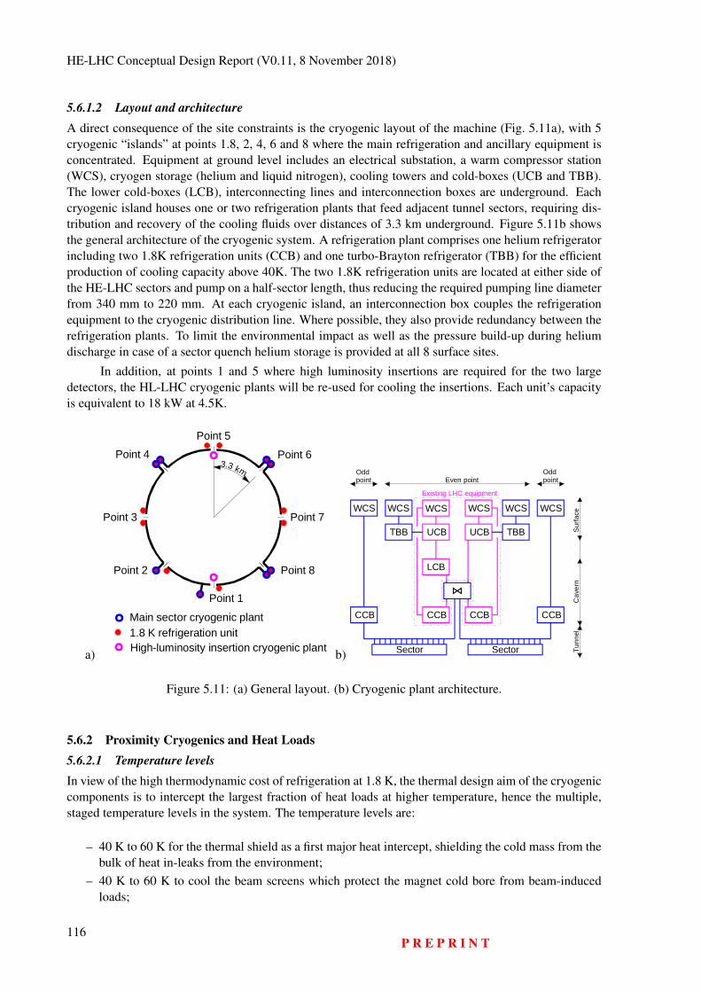
HE-LHC Conceptual Design Report (V0.11, 8 November 2018)
5.6.1.2 Layout and architectureA direct consequence of the site constraints is the cryogenic layout of the machine (Fig. 5.11a), with 5cryogenic “islands” at points 1.8, 2, 4, 6 and 8 where the main refrigeration and ancillary equipment isconcentrated. Equipment at ground level includes an electrical substation, a warm compressor station(WCS), cryogen storage (helium and liquid nitrogen), cooling towers and cold-boxes (UCB and TBB).The lower cold-boxes (LCB), interconnecting lines and interconnection boxes are underground. Eachcryogenic island houses one or two refrigeration plants that feed adjacent tunnel sectors, requiring dis-tribution and recovery of the cooling fluids over distances of 3.3 km underground. Figure 5.11b showsthe general architecture of the cryogenic system. A refrigeration plant comprises one helium refrigeratorincluding two 1.8K refrigeration units (CCB) and one turbo-Brayton refrigerator (TBB) for the efficientproduction of cooling capacity above 40K. The two 1.8K refrigeration units are located at either side ofthe HE-LHC sectors and pump on a half-sector length, thus reducing the required pumping line diameterfrom 340 mm to 220 mm. At each cryogenic island, an interconnection box couples the refrigerationequipment to the cryogenic distribution line. Where possible, they also provide redundancy between therefrigeration plants. To limit the environmental impact as well as the pressure build-up during heliumdischarge in case of a sector quench helium storage is provided at all 8 surface sites.
In addition, at points 1 and 5 where high luminosity insertions are required for the two largedetectors, the HL-LHC cryogenic plants will be re-used for cooling the insertions. Each unit’s capacityis equivalent to 18 kW at 4.5K.
a)
Point 1
Point 2
Point 3
Point 4Point 5
Point 6
Point 7
Point 8
3.3 km
Main sector cryogenic plant1.8 K refrigeration unitHigh-luminosity insertion cryogenic plant b)
UCB UCB
LCB
CCB CCB
WCS WCS
CCB
TBB
WCS
TBB
WCS
Sector
WCS
Sector
CCB
WCSExisting LHC equipment
Even pointOddpoint
Oddpoint
Surfa
ceC
aver
nTu
nnel
Figure 5.11: (a) General layout. (b) Cryogenic plant architecture.
5.6.2 Proximity Cryogenics and Heat Loads5.6.2.1 Temperature levelsIn view of the high thermodynamic cost of refrigeration at 1.8 K, the thermal design aim of the cryogeniccomponents is to intercept the largest fraction of heat loads at higher temperature, hence the multiple,staged temperature levels in the system. The temperature levels are:
– 40 K to 60 K for the thermal shield as a first major heat intercept, shielding the cold mass from thebulk of heat in-leaks from the environment;
– 40 K to 60 K to cool the beam screens which protect the magnet cold bore from beam-inducedloads;
116P R E P R I N T
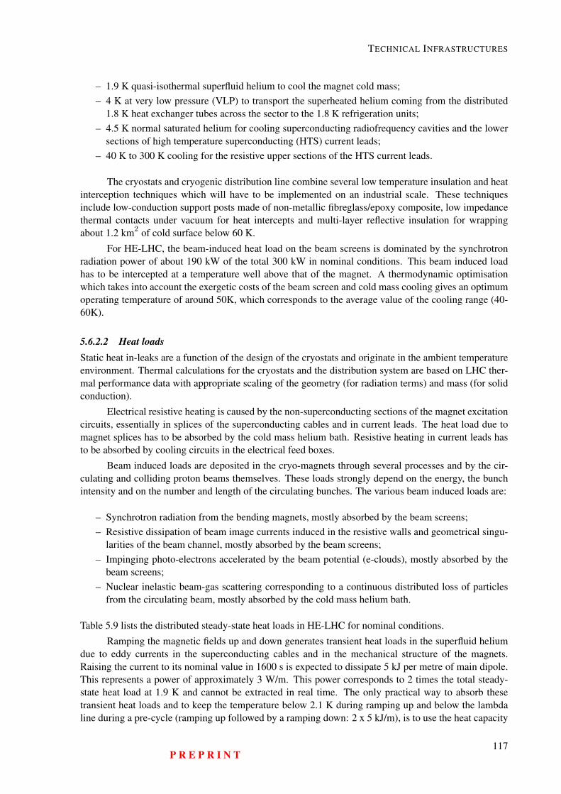
TECHNICAL INFRASTRUCTURES
– 1.9 K quasi-isothermal superfluid helium to cool the magnet cold mass;– 4 K at very low pressure (VLP) to transport the superheated helium coming from the distributed
1.8 K heat exchanger tubes across the sector to the 1.8 K refrigeration units;– 4.5 K normal saturated helium for cooling superconducting radiofrequency cavities and the lower
sections of high temperature superconducting (HTS) current leads;– 40 K to 300 K cooling for the resistive upper sections of the HTS current leads.
The cryostats and cryogenic distribution line combine several low temperature insulation and heatinterception techniques which will have to be implemented on an industrial scale. These techniquesinclude low-conduction support posts made of non-metallic fibreglass/epoxy composite, low impedancethermal contacts under vacuum for heat intercepts and multi-layer reflective insulation for wrappingabout 1.2 km2 of cold surface below 60 K.
For HE-LHC, the beam-induced heat load on the beam screens is dominated by the synchrotronradiation power of about 190 kW of the total 300 kW in nominal conditions. This beam induced loadhas to be intercepted at a temperature well above that of the magnet. A thermodynamic optimisationwhich takes into account the exergetic costs of the beam screen and cold mass cooling gives an optimumoperating temperature of around 50K, which corresponds to the average value of the cooling range (40-60K).
5.6.2.2 Heat loadsStatic heat in-leaks are a function of the design of the cryostats and originate in the ambient temperatureenvironment. Thermal calculations for the cryostats and the distribution system are based on LHC ther-mal performance data with appropriate scaling of the geometry (for radiation terms) and mass (for solidconduction).
Electrical resistive heating is caused by the non-superconducting sections of the magnet excitationcircuits, essentially in splices of the superconducting cables and in current leads. The heat load due tomagnet splices has to be absorbed by the cold mass helium bath. Resistive heating in current leads hasto be absorbed by cooling circuits in the electrical feed boxes.
Beam induced loads are deposited in the cryo-magnets through several processes and by the cir-culating and colliding proton beams themselves. These loads strongly depend on the energy, the bunchintensity and on the number and length of the circulating bunches. The various beam induced loads are:
– Synchrotron radiation from the bending magnets, mostly absorbed by the beam screens;– Resistive dissipation of beam image currents induced in the resistive walls and geometrical singu-
larities of the beam channel, mostly absorbed by the beam screens;– Impinging photo-electrons accelerated by the beam potential (e-clouds), mostly absorbed by the
beam screens;– Nuclear inelastic beam-gas scattering corresponding to a continuous distributed loss of particles
from the circulating beam, mostly absorbed by the cold mass helium bath.
Table 5.9 lists the distributed steady-state heat loads in HE-LHC for nominal conditions.
Ramping the magnetic fields up and down generates transient heat loads in the superfluid heliumdue to eddy currents in the superconducting cables and in the mechanical structure of the magnets.Raising the current to its nominal value in 1600 s is expected to dissipate 5 kJ per metre of main dipole.This represents a power of approximately 3 W/m. This power corresponds to 2 times the total steady-state heat load at 1.9 K and cannot be extracted in real time. The only practical way to absorb thesetransient heat loads and to keep the temperature below 2.1 K during ramping up and below the lambdaline during a pre-cycle (ramping up followed by a ramping down: 2 x 5 kJ/m), is to use the heat capacity
P R E P R I N T117
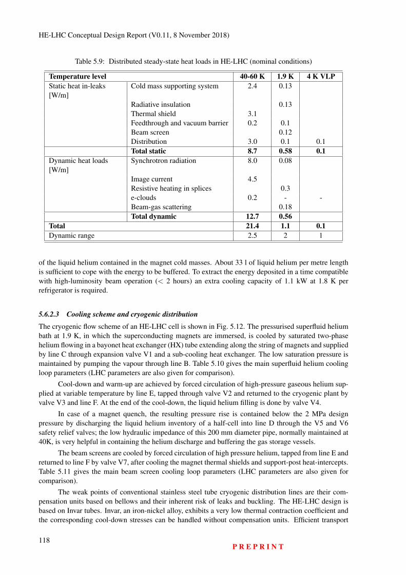
HE-LHC Conceptual Design Report (V0.11, 8 November 2018)
Table 5.9: Distributed steady-state heat loads in HE-LHC (nominal conditions)
Temperature level 40-60 K 1.9 K 4 K VLPStatic heat in-leaks[W/m]
Cold mass supporting system 2.4 0.13
Radiative insulation 0.13Thermal shield 3.1Feedthrough and vacuum barrier 0.2 0.1Beam screen 0.12Distribution 3.0 0.1 0.1Total static 8.7 0.58 0.1
Dynamic heat loads[W/m]
Synchrotron radiation 8.0 0.08
Image current 4.5Resistive heating in splices 0.3e-clouds 0.2 - -Beam-gas scattering 0.18Total dynamic 12.7 0.56
Total 21.4 1.1 0.1Dynamic range 2.5 2 1
of the liquid helium contained in the magnet cold masses. About 33 l of liquid helium per metre lengthis sufficient to cope with the energy to be buffered. To extract the energy deposited in a time compatiblewith high-luminosity beam operation (< 2 hours) an extra cooling capacity of 1.1 kW at 1.8 K perrefrigerator is required.
5.6.2.3 Cooling scheme and cryogenic distribution
The cryogenic flow scheme of an HE-LHC cell is shown in Fig. 5.12. The pressurised superfluid heliumbath at 1.9 K, in which the superconducting magnets are immersed, is cooled by saturated two-phasehelium flowing in a bayonet heat exchanger (HX) tube extending along the string of magnets and suppliedby line C through expansion valve V1 and a sub-cooling heat exchanger. The low saturation pressure ismaintained by pumping the vapour through line B. Table 5.10 gives the main superfluid helium coolingloop parameters (LHC parameters are also given for comparison).
Cool-down and warm-up are achieved by forced circulation of high-pressure gaseous helium sup-plied at variable temperature by line E, tapped through valve V2 and returned to the cryogenic plant byvalve V3 and line F. At the end of the cool-down, the liquid helium filling is done by valve V4.
In case of a magnet quench, the resulting pressure rise is contained below the 2 MPa designpressure by discharging the liquid helium inventory of a half-cell into line D through the V5 and V6safety relief valves; the low hydraulic impedance of this 200 mm diameter pipe, normally maintained at40K, is very helpful in containing the helium discharge and buffering the gas storage vessels.
The beam screens are cooled by forced circulation of high pressure helium, tapped from line E andreturned to line F by valve V7, after cooling the magnet thermal shields and support-post heat-intercepts.Table 5.11 gives the main beam screen cooling loop parameters (LHC parameters are also given forcomparison).
The weak points of conventional stainless steel tube cryogenic distribution lines are their com-pensation units based on bellows and their inherent risk of leaks and buckling. The HE-LHC design isbased on Invar tubes. Invar, an iron-nickel alloy, exhibits a very low thermal contraction coefficient andthe corresponding cool-down stresses can be handled without compensation units. Efficient transport
118P R E P R I N T
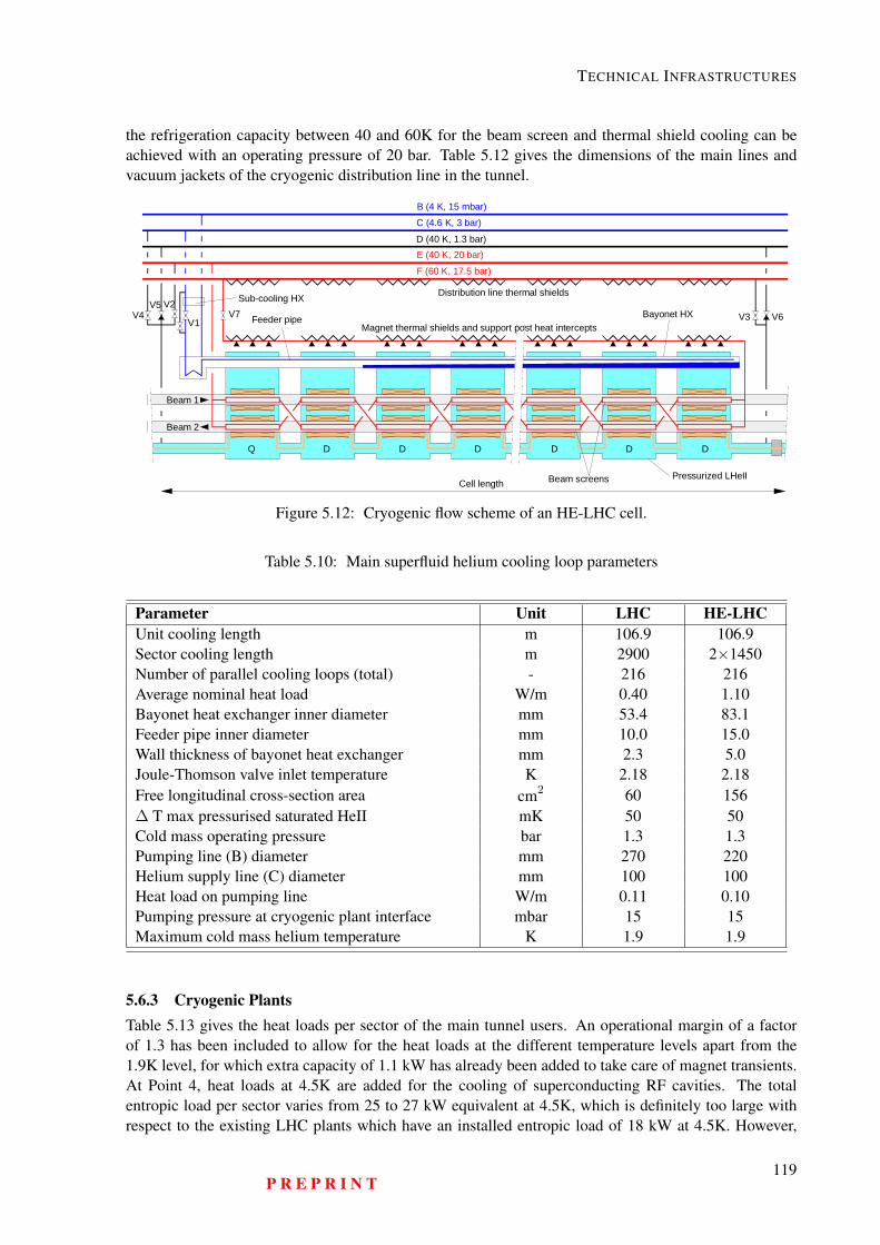
TECHNICAL INFRASTRUCTURES
the refrigeration capacity between 40 and 60K for the beam screen and thermal shield cooling can beachieved with an operating pressure of 20 bar. Table 5.12 gives the dimensions of the main lines andvacuum jackets of the cryogenic distribution line in the tunnel.
E (40 K, 20 bar)
F (60 K, 17.5 bar)
D (40 K, 1.3 bar)
C (4.6 K, 3 bar)B (4 K, 15 mbar)
Cell length
Beam 1
Beam 2
Q D D D D D D
V1
V2V3V4
V5V6V7
Sub-cooling HX
Feeder pipe
Distribution line thermal shields
Magnet thermal shields and support post heat interceptsBayonet HX
Beam screens Pressurized LHeII
Figure 5.12: Cryogenic flow scheme of an HE-LHC cell.
Table 5.10: Main superfluid helium cooling loop parameters
Parameter Unit LHC HE-LHCUnit cooling length m 106.9 106.9Sector cooling length m 2900 2×1450Number of parallel cooling loops (total) - 216 216Average nominal heat load W/m 0.40 1.10Bayonet heat exchanger inner diameter mm 53.4 83.1Feeder pipe inner diameter mm 10.0 15.0Wall thickness of bayonet heat exchanger mm 2.3 5.0Joule-Thomson valve inlet temperature K 2.18 2.18Free longitudinal cross-section area cm2 60 156Δ T max pressurised saturated HeII mK 50 50Cold mass operating pressure bar 1.3 1.3Pumping line (B) diameter mm 270 220Helium supply line (C) diameter mm 100 100Heat load on pumping line W/m 0.11 0.10Pumping pressure at cryogenic plant interface mbar 15 15Maximum cold mass helium temperature K 1.9 1.9
5.6.3 Cryogenic PlantsTable 5.13 gives the heat loads per sector of the main tunnel users. An operational margin of a factorof 1.3 has been included to allow for the heat loads at the different temperature levels apart from the1.9K level, for which extra capacity of 1.1 kW has already been added to take care of magnet transients.At Point 4, heat loads at 4.5K are added for the cooling of superconducting RF cavities. The totalentropic load per sector varies from 25 to 27 kW equivalent at 4.5K, which is definitely too large withrespect to the existing LHC plants which have an installed entropic load of 18 kW at 4.5K. However,
P R E P R I N T119
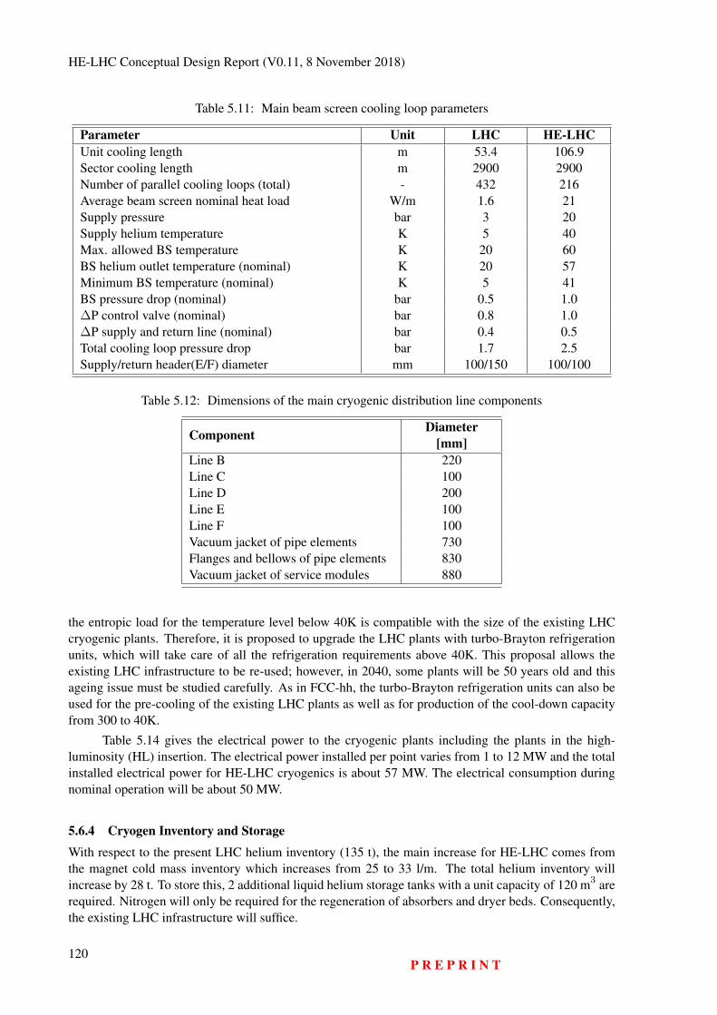
HE-LHC Conceptual Design Report (V0.11, 8 November 2018)
Table 5.11: Main beam screen cooling loop parameters
Parameter Unit LHC HE-LHCUnit cooling length m 53.4 106.9Sector cooling length m 2900 2900Number of parallel cooling loops (total) - 432 216Average beam screen nominal heat load W/m 1.6 21Supply pressure bar 3 20Supply helium temperature K 5 40Max. allowed BS temperature K 20 60BS helium outlet temperature (nominal) K 20 57Minimum BS temperature (nominal) K 5 41BS pressure drop (nominal) bar 0.5 1.0ΔP control valve (nominal) bar 0.8 1.0ΔP supply and return line (nominal) bar 0.4 0.5Total cooling loop pressure drop bar 1.7 2.5Supply/return header(E/F) diameter mm 100/150 100/100
Table 5.12: Dimensions of the main cryogenic distribution line components
Component Diameter[mm]
Line B 220Line C 100Line D 200Line E 100Line F 100Vacuum jacket of pipe elements 730Flanges and bellows of pipe elements 830Vacuum jacket of service modules 880
the entropic load for the temperature level below 40K is compatible with the size of the existing LHCcryogenic plants. Therefore, it is proposed to upgrade the LHC plants with turbo-Brayton refrigerationunits, which will take care of all the refrigeration requirements above 40K. This proposal allows theexisting LHC infrastructure to be re-used; however, in 2040, some plants will be 50 years old and thisageing issue must be studied carefully. As in FCC-hh, the turbo-Brayton refrigeration units can also beused for the pre-cooling of the existing LHC plants as well as for production of the cool-down capacityfrom 300 to 40K.
Table 5.14 gives the electrical power to the cryogenic plants including the plants in the high-luminosity (HL) insertion. The electrical power installed per point varies from 1 to 12 MW and the totalinstalled electrical power for HE-LHC cryogenics is about 57 MW. The electrical consumption duringnominal operation will be about 50 MW.
5.6.4 Cryogen Inventory and Storage
With respect to the present LHC helium inventory (135 t), the main increase for HE-LHC comes fromthe magnet cold mass inventory which increases from 25 to 33 l/m. The total helium inventory willincrease by 28 t. To store this, 2 additional liquid helium storage tanks with a unit capacity of 120 m3 arerequired. Nitrogen will only be required for the regeneration of absorbers and dryer beds. Consequently,the existing LHC infrastructure will suffice.
120P R E P R I N T
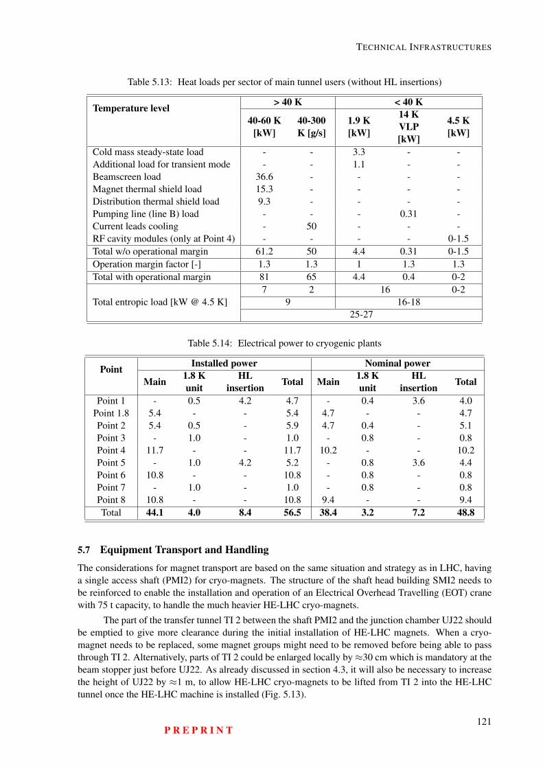
TECHNICAL INFRASTRUCTURES
Table 5.13: Heat loads per sector of main tunnel users (without HL insertions)
Temperature level > 40 K < 40 K
40-60 K[kW]
40-300K [g/s]
1.9 K[kW]
14 KVLP[kW]
4.5 K[kW]
Cold mass steady-state load - - 3.3 - -Additional load for transient mode - - 1.1 - -Beamscreen load 36.6 - - - -Magnet thermal shield load 15.3 - - - -Distribution thermal shield load 9.3 - - - -Pumping line (line B) load - - - 0.31 -Current leads cooling - 50 - - -RF cavity modules (only at Point 4) - - - - 0-1.5Total w/o operational margin 61.2 50 4.4 0.31 0-1.5Operation margin factor [-] 1.3 1.3 1 1.3 1.3Total with operational margin 81 65 4.4 0.4 0-2
Total entropic load [kW @ 4.5 K]7 2 16 0-2
9 16-1825-27
Table 5.14: Electrical power to cryogenic plants
Point Installed power Nominal power
Main 1.8 Kunit
HLinsertion Total Main 1.8 K
unitHL
insertion Total
Point 1 - 0.5 4.2 4.7 - 0.4 3.6 4.0Point 1.8 5.4 - - 5.4 4.7 - - 4.7Point 2 5.4 0.5 - 5.9 4.7 0.4 - 5.1Point 3 - 1.0 - 1.0 - 0.8 - 0.8Point 4 11.7 - - 11.7 10.2 - - 10.2Point 5 - 1.0 4.2 5.2 - 0.8 3.6 4.4Point 6 10.8 - - 10.8 - 0.8 - 0.8Point 7 - 1.0 - 1.0 - 0.8 - 0.8Point 8 10.8 - - 10.8 9.4 - - 9.4Total 44.1 4.0 8.4 56.5 38.4 3.2 7.2 48.8
5.7 Equipment Transport and Handling
The considerations for magnet transport are based on the same situation and strategy as in LHC, havinga single access shaft (PMI2) for cryo-magnets. The structure of the shaft head building SMI2 needs tobe reinforced to enable the installation and operation of an Electrical Overhead Travelling (EOT) cranewith 75 t capacity, to handle the much heavier HE-LHC cryo-magnets.
The part of the transfer tunnel TI 2 between the shaft PMI2 and the junction chamber UJ22 shouldbe emptied to give more clearance during the initial installation of HE-LHC magnets. When a cryo-magnet needs to be replaced, some magnet groups might need to be removed before being able to passthrough TI 2. Alternatively, parts of TI 2 could be enlarged locally by≈30 cm which is mandatory at thebeam stopper just before UJ22. As already discussed in section 4.3, it will also be necessary to increasethe height of UJ22 by ≈1 m, to allow HE-LHC cryo-magnets to be lifted from TI 2 into the HE-LHCtunnel once the HE-LHC machine is installed (Fig. 5.13).
P R E P R I N T121
HE-LHC Conceptual Design Report (V0.11, 8 November 2018)
Because of the bigger diameter and greater weight of the HE-LHC cryo-magnets compared totheir LHC counterparts, and the space constraints in the LHC tunnel, they will be more cumbersome totransport and install. The installation must start from point 7 clockwise and anti-clockwise towards TI2, to avoid having to pass cryo-magnets which have already been installed. Magnets must be installedstrictly sequentially because there is so little clearance that there is a high risk of collision if there was atransport hiccup.
The LHC principle for transport, unloading and lateral transfer will be applied for HE-LHC: trac-tors, trailers and lifting tables will be used. Because of the more restricted space it will be necessary toinstall either lifting anchors or a lifting rail all along the LHC tunnel ceiling. These will be used to liftthe cryo-magnets from the trailer and to lower them onto the transfer tables, for lateral transfer onto thesupport jacks (final positioning).
The vehicles will be custom-made due to the heavy load and space constraints and their mainfeatures will be:
– Battery powered;– Autonomous driving;– 3D guiding system;– Speed:
– In machine tunnel: 3 km/h (loaded) during the initial installation; < 1 km/h during replace-ment of an installed cryo-magnet;
– In TI 2 tunnel: 1 km/h (loaded) during the initial installation (important slope); < 1 km/hduring replacement of an installed cryo-magnet.
5.8 Personnel TransportNo changes are planned for the transport of personnel, compared to LHC. People can either be trans-ported collectively on wagons pulled by electric tractors, or use individual transport means like electrictractors or (electric) bicycles.
5.9 Geodesy, Survey and AlignmentIt is assumed that the demands in terms of positioning accuracy will be the same as those for the LHC.Present technical possibilities have to be compared to future physics requirements, to define which de-velopments need to be undertaken.
5.9.1 Alignment TolerancesThe alignment precision requirements will drive any survey study. The absolute accuracy in the verticaldirection is the deviation from the theoretical plane of the collider, whilst in the transverse plane itis the variation of its radius with respect to the theoretical value. The differential variations betweenseveral consecutive magnets is the relative accuracy. This latter type of error has a more direct effecton the closed orbit of the particles. A value of several mm has been assumed as the requirement for theabsolute accuracy (this was achieved for the LEP and LHC). A relative misalignment of 0.5 mm (1σ)between consecutive quadrupoles and 0.1 mrad (1σ) for the roll angle are the values achieved for theLHC. This error budget has to be shared between mechanical errors, due mainly to the assembly processand alignment errors, including misalignments due to ground motion or mechanical constraints.
5.9.2 GeodesyAs the area covered by the HE-LHC is the same as that of the LHC, only an upgrade of the mean sealevel equipotential surface of gravity (also called the geoid) will be necessary. The LHC was aligned
122P R E P R I N T
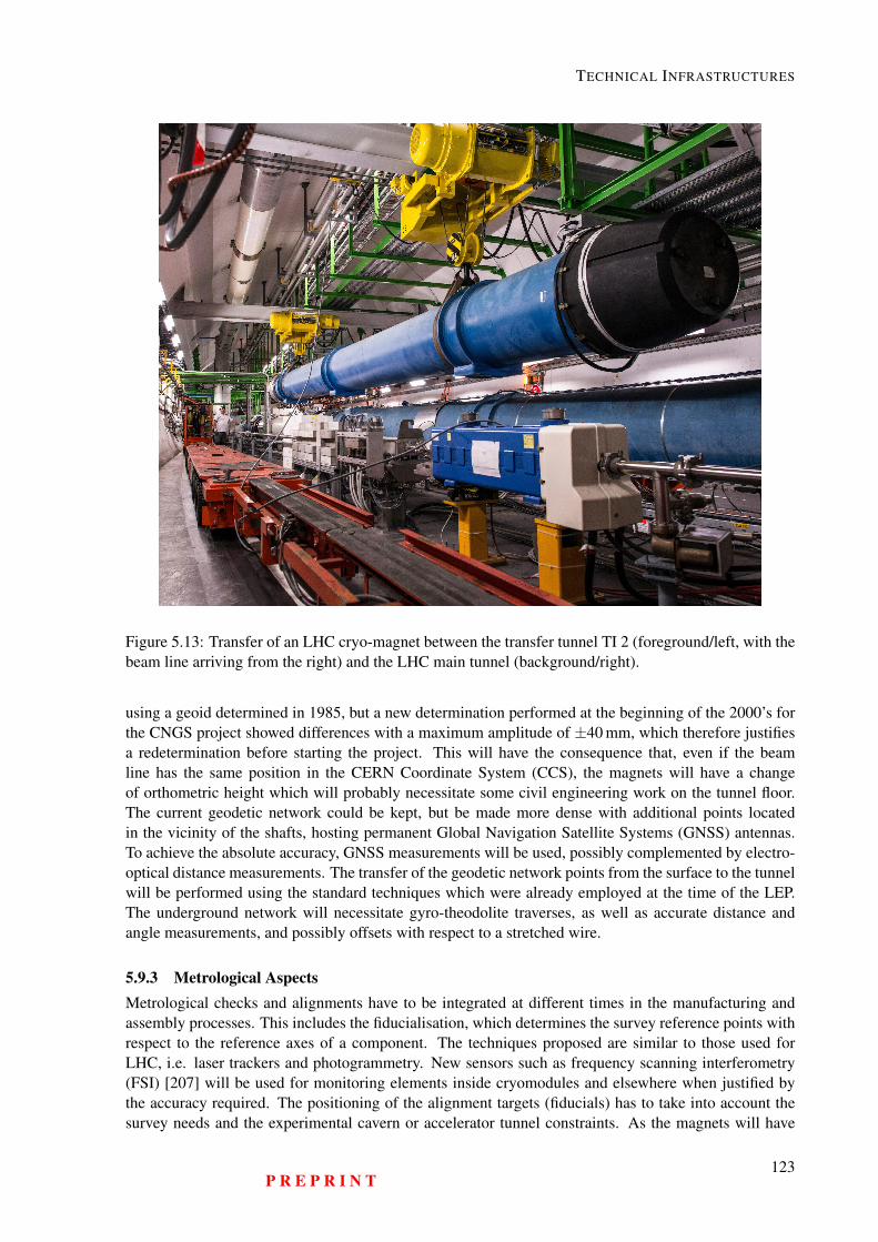
TECHNICAL INFRASTRUCTURES
Figure 5.13: Transfer of an LHC cryo-magnet between the transfer tunnel TI 2 (foreground/left, with thebeam line arriving from the right) and the LHC main tunnel (background/right).
using a geoid determined in 1985, but a new determination performed at the beginning of the 2000’s forthe CNGS project showed differences with a maximum amplitude of ±40 mm, which therefore justifiesa redetermination before starting the project. This will have the consequence that, even if the beamline has the same position in the CERN Coordinate System (CCS), the magnets will have a changeof orthometric height which will probably necessitate some civil engineering work on the tunnel floor.The current geodetic network could be kept, but be made more dense with additional points locatedin the vicinity of the shafts, hosting permanent Global Navigation Satellite Systems (GNSS) antennas.To achieve the absolute accuracy, GNSS measurements will be used, possibly complemented by electro-optical distance measurements. The transfer of the geodetic network points from the surface to the tunnelwill be performed using the standard techniques which were already employed at the time of the LEP.The underground network will necessitate gyro-theodolite traverses, as well as accurate distance andangle measurements, and possibly offsets with respect to a stretched wire.
5.9.3 Metrological AspectsMetrological checks and alignments have to be integrated at different times in the manufacturing andassembly processes. This includes the fiducialisation, which determines the survey reference points withrespect to the reference axes of a component. The techniques proposed are similar to those used forLHC, i.e. laser trackers and photogrammetry. New sensors such as frequency scanning interferometry(FSI) [207] will be used for monitoring elements inside cryomodules and elsewhere when justified bythe accuracy required. The positioning of the alignment targets (fiducials) has to take into account thesurvey needs and the experimental cavern or accelerator tunnel constraints. As the magnets will have
P R E P R I N T123
HE-LHC Conceptual Design Report (V0.11, 8 November 2018)
a larger diameter and the height of the beam with respect to the floor will be kept the same as that ofthe LHC, the design of the equipment supports will be challenging in order to comply with the availablespace, the weight of the magnets and the alignment specifications and constraints.
5.9.4 Alignment of the Accelerator ComponentsThe alignment of the accelerator components will be done in two steps:
– The first “absolute” alignment from the underground network will be performed using standarddigital level and total station measurements.
– The “relative” alignment or smoothing. As the length of the cell is not yet fixed, the values for theLHC have been assumed. The levelling technique offset with respect to a stretched wire will bere-used. If tunnel access time is limited, measurements and realignments will have to be performedrapidly and the development of survey and alignment trains will have to be considered.
5.9.5 Interaction Regions and Collimators AreasThe alignment accuracy for the interaction regions is assumed to be the same as for the LHC, i.e. 0.1 mmfor the triplets located on the same side of the IP, 0.2 mm from left side of the IP to the right side and0.5-1.2 mm from the triplets line to the detector (all values given at 1σ). To achieve these specifications,the survey galleries will be used to host part of a permanent monitoring system based on the latest sensortechnology available.
Due to the high level of radiation in the collimator areas, a permanent monitoring system, oran automatic measuring solution using a survey train, will be used together with a remote controlledre-alignment system. They will be based on the latest developments implemented for the HL-LHC.A robotic solution must also be developed to maintain, dismantle and re-install the permanent surveysystems.
5.9.6 ExperimentsThe alignment accuracy for assembly of the experiment is assumed to be similar to those of Atlas andCMS i.e. 0.5 mm. The positioning of the experiment with respect to the beam line is done using ageodetic network for the experiment derived from the underground network. It is composed of pointsdistributed across the whole cavern volume on the walls and floor. It is used at all stages of the assemblyand positioning of the detectors. It is measured once the cavern has been delivered and is still empty,using mainly distances, angles and levelling measurements. The use of 3D laser tracker technology isappropriate for this type of 3D network. From this network, only the outer skin of the experiment isvisible and therefore the position of the inner detectors will be reconstructed from the position of theexternal fiducials and the fiducialisation and assembly measurements.
5.10 Communications, Computing and Data ServicesDuring the LHC operation era computing for particle accelerators and the experiments has evolved intoa service for a world-wide user community. Adopting products and best practices that emerge from anever-growing Information and Communication Technologies (ICT) industry has proven to be a cost andperformance effective path to serve the community. Large-scale science projects used to be a driver ofIT infrastructure developments [208–213]. A future particle collider research facility can again be a caseand a driving force for advanced ICT developments in areas that go beyond the hardware and softwaredomains, which dominated the particle accelerator projects of the 1980’s and 90’s.
A set of general services comprising wired and wireless networks, desktop, mobile and centralisedcomputing for all users, various storage system tiers, software and data provisioning, authentication and
124P R E P R I N T
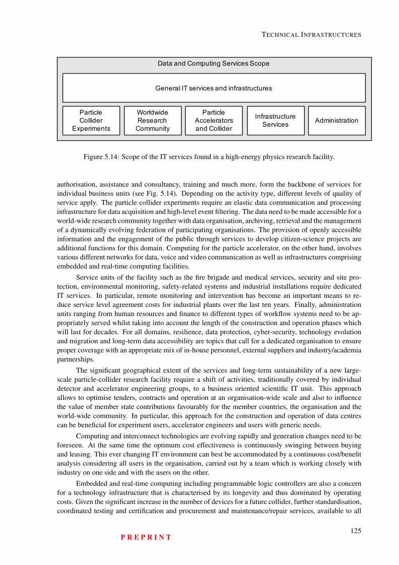
TECHNICAL INFRASTRUCTURES
Data and Computing Services Scope
ParticleCollider
Experiments
ParticleAcceleratorsand Collider
InfrastructureServices Administration
WorldwideResearch
Community
General IT services and infrastructures
Figure 5.14: Scope of the IT services found in a high-energy physics research facility.
authorisation, assistance and consultancy, training and much more, form the backbone of services forindividual business units (see Fig. 5.14). Depending on the activity type, different levels of quality ofservice apply. The particle collider experiments require an elastic data communication and processinginfrastructure for data acquisition and high-level event filtering. The data need to be made accessible for aworld-wide research community together with data organisation, archiving, retrieval and the managementof a dynamically evolving federation of participating organisations. The provision of openly accessibleinformation and the engagement of the public through services to develop citizen-science projects areadditional functions for this domain. Computing for the particle accelerator, on the other hand, involvesvarious different networks for data, voice and video communication as well as infrastructures comprisingembedded and real-time computing facilities.
Service units of the facility such as the fire brigade and medical services, security and site pro-tection, environmental monitoring, safety-related systems and industrial installations require dedicatedIT services. In particular, remote monitoring and intervention has become an important means to re-duce service level agreement costs for industrial plants over the last ten years. Finally, administrationunits ranging from human resources and finance to different types of workflow systems need to be ap-propriately served whilst taking into account the length of the construction and operation phases whichwill last for decades. For all domains, resilience, data protection, cyber-security, technology evolutionand migration and long-term data accessibility are topics that call for a dedicated organisation to ensureproper coverage with an appropriate mix of in-house personnel, external suppliers and industry/academiapartnerships.
The significant geographical extent of the services and long-term sustainability of a new large-scale particle-collider research facility require a shift of activities, traditionally covered by individualdetector and accelerator engineering groups, to a business oriented scientific IT unit. This approachallows to optimise tenders, contracts and operation at an organisation-wide scale and also to influencethe value of member state contributions favourably for the member countries, the organisation and theworld-wide community. In particular, this approach for the construction and operation of data centrescan be beneficial for experiment users, accelerator engineers and users with generic needs.
Computing and interconnect technologies are evolving rapidly and generation changes need to beforeseen. At the same time the optimum cost effectiveness is continuously swinging between buyingand leasing. This ever changing IT environment can best be accommodated by a continuous cost/benefitanalysis considering all users in the organisation, carried out by a team which is working closely withindustry on one side and with the users on the other.
Embedded and real-time computing including programmable logic controllers are also a concernfor a technology infrastructure that is characterised by its longevity and thus dominated by operatingcosts. Given the significant increase in the number of devices for a future collider, further standardisation,coordinated testing and certification and procurement and maintenance/repair services, available to all
P R E P R I N T125
HE-LHC Conceptual Design Report (V0.11, 8 November 2018)
users of the organisation, will help to improve the cost effectiveness. A large-scale particle acceleratorbuilding on decades of engineers experience presents an ideal case for an openly available architectureand platform for supervisory control to integrate the diverse subsystems. A system that can evolvewith emerging ”Internet of Things” (IoT) products and yet unanticipated device technologies can createimpact far beyond the particle accelerator community.
Cyber-security plays an increasingly important role in IT systems and embedded computing is noexception to this. The use of processors, operating systems and embedded Web servers in the majorityof programmable laboratory equipment such as simple digital I/O devices, measurement instruments,oscilloscopes and autonomous robots already require a well organised infrastructure. This is supportedby a process that leads to a secure environment on one side and which has the least possible impact onusability on the other side. For example, it should allow the possibility of developing and deployingacross network boundaries, create islands and sandboxes to limit potential harm, have transparent virusand malware checking and isolation, have system updates that have little or no impact on work effi-ciency, provide coordinated rollback and much more. This evolution is expected to continue and the IoTapproach will also require an organisation wide vertical integration of services across the horizontal userdomains [165].
Cooperation on IT standards, technology developments and organisation with other research fa-cilities which have similar requirements (e.g. DESY, ESRF, ESS, Fermilab) needs to be strengthened.Synergies with other scientific domains (e.g. astronomy and radioastronomy facilities, material scienceswith light sources and FELs, astrophysics installations such as neutrino and gravitational wave observa-tories, particle accelerators for medical applications and nuclear fusion experiments) can be developed tolead to more effective operation of world-wide IT services for research. Activities spawned by DESY onfront-end computing hardware [214] and CERN’s openlab [215] are good examples for such initiatives.
The geographical extent of a 100 km long particle collider across the canton of Geneva and farinto the Haute Savoie region suggests the development of cooperation with the host state communicationnetwork providers and with telecom operators. Improving the high-tech communication, computing anddata service infrastructure in the region is high on the agenda of the host state authorities with an ambitionto become a "European Silicon Valley" [216]. It creates further potential for the strengthening of CERNas a focal point of high-technology in a region in which the population approaches 2 million (departmentsAin and Haute Savoie, canton Geneva) and which also has a high annual growth rate [217].
Possible services do not only include fibre optics and data centres that can be shared with academicpartners but can also include mobile communication and the cooperation with emergency and rescueservices in a cross-border context. CERN’s activities concerning the establishment of the TETRA radiocommunication system in the region are a first step in this direction [218]. CERN’s particular status ascarrier-neutral Internet eXchange Point (CIXP) [219] will gain importance in a technology ecosystemthat becomes ever more dominated by profit making organisations which are building and operatingglobal communication infrastructures. These collaborations may help to ensure that non-profit makingorganisations continue to operate independently and become less dependent on infrastructure operatorpriorities, which may favour financially stronger commercial clients.
Beyond the regional scale, the LHC programme has shown the value of a world-wide computingand communication infrastructure to make the research data available to scientists in all participatingcountries [220]. The success of a future particle collider programme will rely even more on internationalparticipation. Many potential participating countries are not part of CERN’s global vision today andsome are still technologically underserved. The SESAME light-source under the auspices of UNESCOis a great example of such an initiatives [221]. The capacity to plan, develop and implement a world-wide inclusion policy goes beyond the scope of the high energy physics community and is therefore also agood opportunity to establish a common strategy with other scientific disciplines. A timely developmentof such an initiative will help raising the interest and acceptance level of large-scale investments in aninfrastructure focusing on fundamental scientific research.
126P R E P R I N T
TECHNICAL INFRASTRUCTURES
Considering the fast evolution of information technologies in all domains [222], the long term costimpact of in-house technology developments and their potentially limited large scale impact, it is prudentto base architectures for the particle accelerator and the experiment data processing environments onindustrial hardware, software and service infrastructures. The particular needs of an FCC-scale facilitymay, however, also represent attractive test-beds for emerging technologies. Co-innovation projectswith industrial partners during the early construction phase, permitting pre-commercial procurementinitiatives that can lead to high-performance infrastructure services at a competitive cost are one way tooptimise this situation [223].
A preliminary cost-benefit-analysis of the LHC programme [224] revealed that one third of theinfrastructure’s value is generated through training. The ICT sector represents an ideal case for train-ing at large with ever growing societal and industrial demands. Early stage researchers and engineersare much appreciated participants in CERN’s technology programmes, which give them opportunities toacquire skills that are also high on the wish list of industry. It would be possible to extend these train-ing programmes to participating industrial partners, generating value for industry directly. The CERNopenlab public-private partnership already demonstrates the validity of this approach. Further industrialcooperation can focus on field testing of pre-commercial products and services, common optimisation,development of standards and best-practices and co-innovation with the research infrastructures as ademonstration case. These activities would be carried out in low risk environment for industrial partnersof any size. The scaling up of the open, industrial SCADA platform PVSS around the year 2000 is oneexample of the success of this approach [225]. Eventually, the company was integrated in the SIEMENSgroup and the software has been re-branded as WinCC OA to become the SIEMENS flagship SCADAsystem on the global scale.
Finally, long-term data availability [226] has become an important aspect of ensuring the lastingimpact of the facility [227]. The accessibility of several decades worth of raw LHC data, all metadataand previous analysis results has turned out to be a major topic for the ICT community. With a futureparticle collider, the time span will extend to the end of the 21st century, calling for evolving data storageand management systems that serve the worldwide particle physics community for more than 100 years.Considering the continuous evolution of data formats, the ever-changing particle detectors and a highlydynamic user community, data quality management is a primary topic. The value of a particle colliderresearch facility depends directly on its quality and long term world-wide accessibility for as large acommunity of scientists as possible.
5.11 Safety and Access Management SystemsA safety management system (SMS) for a future large-scale particle collider will be based on an indus-try best-practice system which integrates, in a uniform and regulatory-compliant way, everything whichcontributes to safe operation. This system also includes the procedures associated with the different op-erating conditions encountered during the lifetime of the collider. A high-level computer-based safetymanagement system integrates underlying safety related functions, including fire detection, oxygen defi-ciency detection, smoke and helium extraction systems, fire extinction systems, access and authorisationmanagement, door supervision and control, video surveillance, radiation monitoring, conventional envi-ronmental monitoring, evacuation signalling, supervision and control of lifts, communication with peoplein underground zones, emergency lighting and acoustics and communication with emergency services(fire fighting, rescue, healthcare providers, public and private security forces). The sub-systems functionautonomously.
There are two complementary systems for personnel protection in the underground areas: theaccess safety system and the access control system. During machine operation, the access safety systemprotects personnel from the hazards arising from the operation of the accelerator and from the beams. Itacts through interlocks on important safety elements of the accelerator. By interlocking these elementsit is possible to establish the right accelerator and equipment conditions in order to allow authorised
P R E P R I N T127

HE-LHC Conceptual Design Report (V0.11, 8 November 2018)
personnel to access the underground installations or to allow the restart of the accelerator equipmentwhen access is finished. When the accelerator is not operating with beam and is in access mode, theaccess control system allows the positive identification of any person requesting access and ensures thatall pre-requisites and authorisations for that person are valid. For operational and/or safety reasons, theaccess control system also limits the number of people present simultaneously in the underground areas.
An automatic fire detection system consisting of detectors and air sampling networks to detectthe presence of smoke is connected to control and monitoring equipment located in one of the surfacebuildings at each point. If fire or smoke is detected, the system launches automatic safety functionsand alerts the fire and rescue service. Fire detection is installed in all underground areas and will allowaccurate location of a fire. Underground areas will also be equipped with communication channels toallow a user to contact the fire and rescue service directly. An automatic oxygen deficiency detectionsystem warns users of the danger and alerts the fire and rescue service.
The SMS launches safety functions if there is a fire or oxygen deficiency is detected. Thesefunctions include compartmentalisation, evacuation and smoke extraction. The CERN fire brigade hasthe possibility to trigger these functions remotely and to broadcast safety instructions in the various areasof the facility.
The emergency evacuation system is a part of the automatic protection system. It broadcastsaudible evacuation signals triggered either automatically by a safety system, such as fire or oxygendeficiency detection, or manually by pushing one of the emergency evacuation buttons installed withinthe area in question.
The SMS provides prioritised and homogeneous visualisation of the status of all safety relevant pa-rameters, allows the supervisory control of all sub-systems and handles the sub-system interconnections.The SMS communicates with the sub-systems through fail-safe protocols, over a dedicated communi-cation infrastructure. It guarantees that critical alarms are automatically transmitted to the competentservices (e.g. fire brigade, radiation protection team) and that all incidents are recorded and suitablydocumented for potential internal and external examination (auditing). Furthermore, the SMS ensuresthat any condition which is incompatible with safe beam operation (e.g. intrusion) is detected and thebeam is aborted.
Such supervisory systems are in daily operation in most large-scale plants (e.g. particle-acceleratorbased ion therapy facilities, oil and gas rigs, manufacturing and processing plants).
The future system must be compliant with international norms, be open and extensible and beconfigurable to the specific application (e.g. GIS and CAD integration, user interface designer). Process-ing speed is generally not critical, but the system must work extremely reliably, be highly scalable andbe open to the integration of a continuously growing set of diverse subsystems from different suppliers.Implementation details (e.g. positioning of a central supervision point, the number and position of de-centralised facilities to interact with the system, hard- and software choices, rights management, meansto identify people requesting access, or locating people in the machine) will be subject to a requirementsspecification phase, once the detailed design of the infrastructure and its individual technical systems arewell known.
128P R E P R I N T
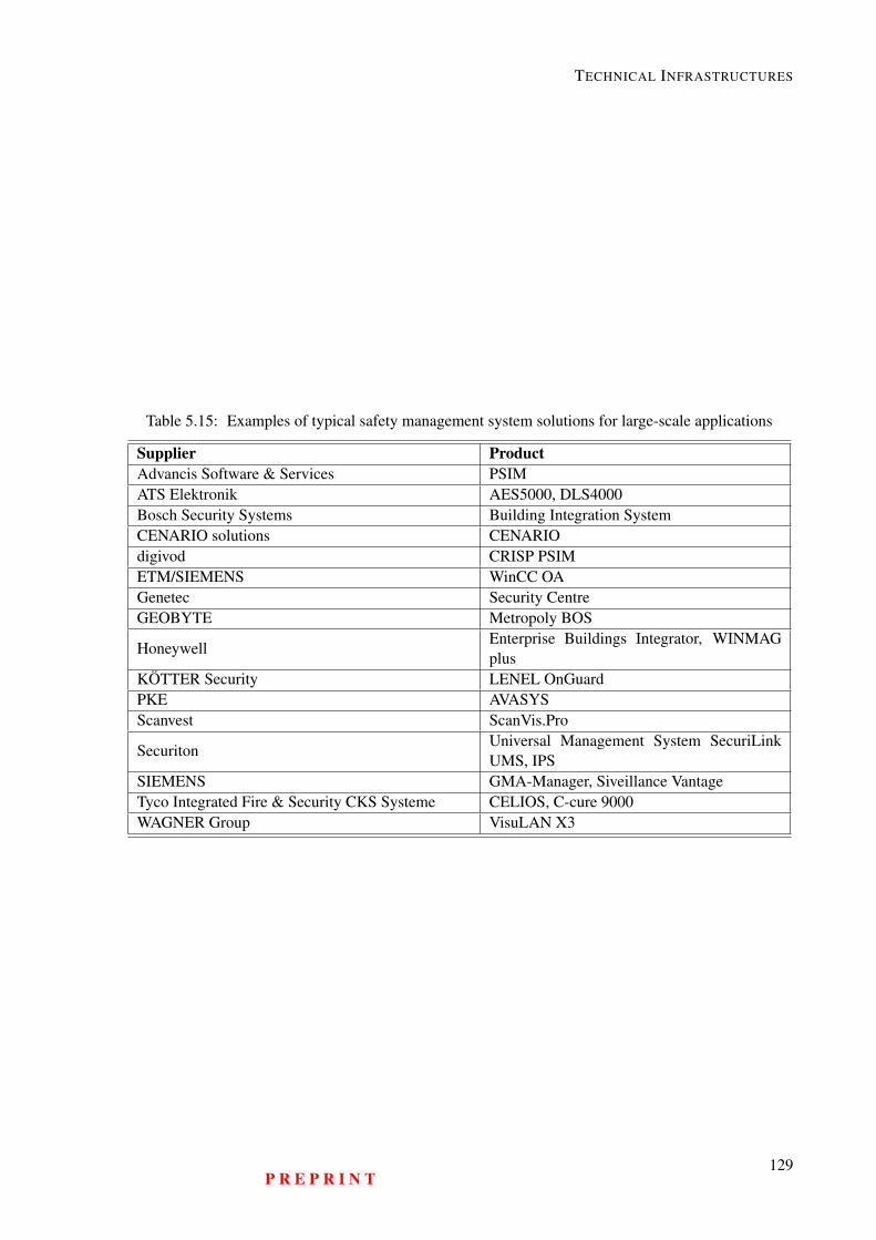
TECHNICAL INFRASTRUCTURES
Table 5.15: Examples of typical safety management system solutions for large-scale applications
Supplier ProductAdvancis Software & Services PSIMATS Elektronik AES5000, DLS4000Bosch Security Systems Building Integration SystemCENARIO solutions CENARIOdigivod CRISP PSIMETM/SIEMENS WinCC OAGenetec Security CentreGEOBYTE Metropoly BOS
HoneywellEnterprise Buildings Integrator, WINMAGplus
KÖTTER Security LENEL OnGuardPKE AVASYSScanvest ScanVis.Pro
SecuritonUniversal Management System SecuriLinkUMS, IPS
SIEMENS GMA-Manager, Siveillance VantageTyco Integrated Fire & Security CKS Systeme CELIOS, C-cure 9000WAGNER Group VisuLAN X3
P R E P R I N T129

HE-LHC Conceptual Design Report (V0.11, 8 November 2018)
130P R E P R I N T
Chapter 6
Injector Scenarios
6.1 Requirements and Basic Assumptions
The HE-LHC injector chain needs to be able to fill the HE-LHC with the 2808 nominal 25 ns protonbunches in around 10 minutes, as is possible at present (at least on paper) for the LHC. The bunchintensity required is 2.2 × 10¹¹ protons in a normalised emittance of 2.5 µm, as is needed for the HL-LHC.
The pre-injector chain will be Linac4, PSB, PS and SPS (the present LHC injector chain), inaddition to the HEB (see Fig. 6.1). The performance is assumed to be the same as that of the chain afterthe LHC Injector Upgrade (LIU) project (see Table 6.1), for which the expected performance at 25 ns isthat required by HE-LHC.
The HE-LHC injection energies under study are 450 GeV, available without modification fromtoday’s LHC injector system and 1.3 TeV from a new High Energy Booster (HEB) located in the existing6.9 km long SPS tunnel. A higher energy is favourable in terms of impedance, beam stability, apertureand energy (field) swing, but for transfer to HE-LHC and simplicity (and cost) of the injector complex alower energy is preferred. The overall project optimisation needs to take into account all these factors,as well as the capital and operation costs.
For the final machine, an intermediate energy (of say 900 GeV) may prove to be the optimum - butat this conceptual design stage the 1.3 GeV version is the only new HEB machine to have been studiedexplicitly, in synergy with the study for the FCC-hh injectors.
It is assumed that today’s TI 2 and TI 8 transfer line tunnels are retained, although for energiesabove 450 GeV new superconducting transfer magnets will be mandatory.
Due to the need to avoid damage to the injection protection absorbers the number of buncheswhich can be safely transferred to HE-LHC is determined by the injection energy. This limit scales non-linearly with beam energy, as the energy deposition in the absorber also depends on the secondary showerdevelopment. It is assumed that 320b per transfer are possible at 1.3 TeV, corresponding to around 8 µs ofthe 23 µs SPS tunnel circumference. Therefore, as for the LHC today, around 10 extractions are neededto fill each HE-LHC ring.
Any additional HEB should have a high degree of flexibility in terms of stability and insensitivityto configuration changes, since in addition to filling HE-LHC several times per day, it will also be calledupon to serve multiple users e.g. beams for material test facilities and fixed target (FT) experiments usingslow extraction.
Other important requirements are that the injector chain including the HEB should have high avail-ability, to minimise the impact on the HE-LHC collider availability and the HEB should be considerablyeasier to operate than the collider itself.
131
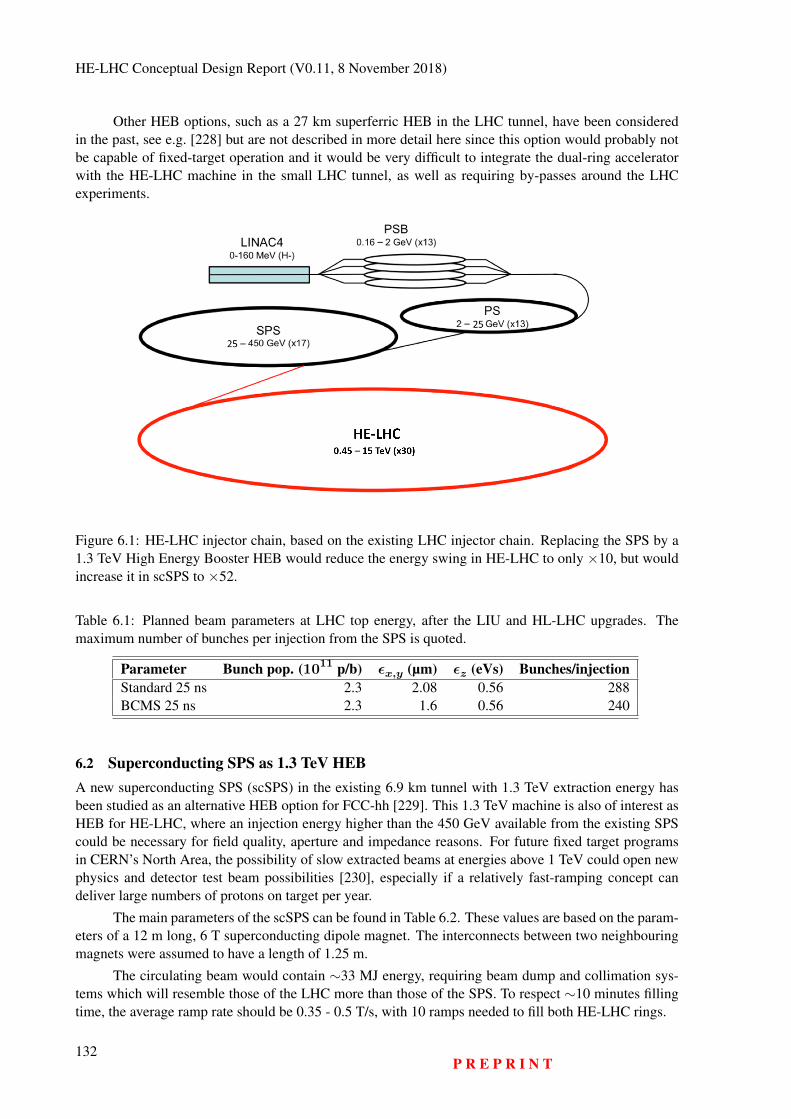
HE-LHC Conceptual Design Report (V0.11, 8 November 2018)
Other HEB options, such as a 27 km superferric HEB in the LHC tunnel, have been consideredin the past, see e.g. [228] but are not described in more detail here since this option would probably notbe capable of fixed-target operation and it would be very difficult to integrate the dual-ring acceleratorwith the HE-LHC machine in the small LHC tunnel, as well as requiring by-passes around the LHCexperiments.
Figure 6.1: HE-LHC injector chain, based on the existing LHC injector chain. Replacing the SPS by a1.3 TeV High Energy Booster HEB would reduce the energy swing in HE-LHC to only ×10, but wouldincrease it in scSPS to ×52.
Table 6.1: Planned beam parameters at LHC top energy, after the LIU and HL-LHC upgrades. Themaximum number of bunches per injection from the SPS is quoted.
Parameter Bunch pop. (1011 p/b) εx,y (µm) εz (eVs) Bunches/injectionStandard 25 ns 2.3 2.08 0.56 288BCMS 25 ns 2.3 1.6 0.56 240
6.2 Superconducting SPS as 1.3 TeV HEBA new superconducting SPS (scSPS) in the existing 6.9 km tunnel with 1.3 TeV extraction energy hasbeen studied as an alternative HEB option for FCC-hh [229]. This 1.3 TeV machine is also of interest asHEB for HE-LHC, where an injection energy higher than the 450 GeV available from the existing SPScould be necessary for field quality, aperture and impedance reasons. For future fixed target programsin CERN’s North Area, the possibility of slow extracted beams at energies above 1 TeV could open newphysics and detector test beam possibilities [230], especially if a relatively fast-ramping concept candeliver large numbers of protons on target per year.
The main parameters of the scSPS can be found in Table 6.2. These values are based on the param-eters of a 12 m long, 6 T superconducting dipole magnet. The interconnects between two neighbouringmagnets were assumed to have a length of 1.25 m.
The circulating beam would contain ∼33 MJ energy, requiring beam dump and collimation sys-tems which will resemble those of the LHC more than those of the SPS. To respect ∼10 minutes fillingtime, the average ramp rate should be 0.35 - 0.5 T/s, with 10 ramps needed to fill both HE-LHC rings.
132P R E P R I N T
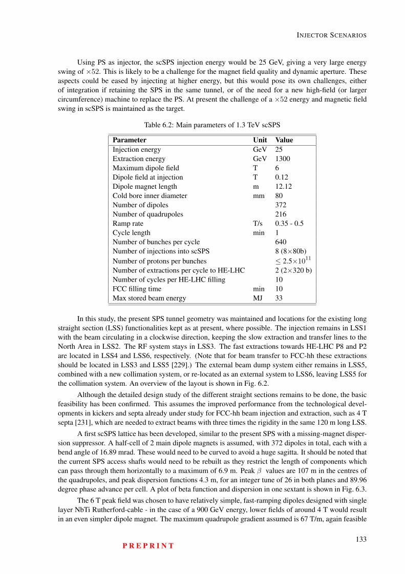
INJECTOR SCENARIOS
Using PS as injector, the scSPS injection energy would be 25 GeV, giving a very large energyswing of ×52. This is likely to be a challenge for the magnet field quality and dynamic aperture. Theseaspects could be eased by injecting at higher energy, but this would pose its own challenges, eitherof integration if retaining the SPS in the same tunnel, or of the need for a new high-field (or largercircumference) machine to replace the PS. At present the challenge of a ×52 energy and magnetic fieldswing in scSPS is maintained as the target.
Table 6.2: Main parameters of 1.3 TeV scSPS
Parameter Unit ValueInjection energy GeV 25Extraction energy GeV 1300Maximum dipole field T 6Dipole field at injection T 0.12Dipole magnet length m 12.12Cold bore inner diameter mm 80Number of dipoles 372Number of quadrupoles 216Ramp rate T/s 0.35 - 0.5Cycle length min 1Number of bunches per cycle 640Number of injections into scSPS 8 (8×80b)Number of protons per bunches ≤ 2.5×10¹¹
Number of extractions per cycle to HE-LHC 2 (2×320 b)Number of cycles per HE-LHC filling 10FCC filling time min 10Max stored beam energy MJ 33
In this study, the present SPS tunnel geometry was maintained and locations for the existing longstraight section (LSS) functionalities kept as at present, where possible. The injection remains in LSS1with the beam circulating in a clockwise direction, keeping the slow extraction and transfer lines to theNorth Area in LSS2. The RF system stays in LSS3. The fast extractions towards HE-LHC P8 and P2are located in LSS4 and LSS6, respectively. (Note that for beam transfer to FCC-hh these extractionsshould be located in LSS3 and LSS5 [229].) The external beam dump system either remains in LSS5,combined with a new collimation system, or re-located as an external system to LSS6, leaving LSS5 forthe collimation system. An overview of the layout is shown in Fig. 6.2.
Although the detailed design study of the different straight sections remains to be done, the basicfeasibility has been confirmed. This assumes the improved performance from the technological devel-opments in kickers and septa already under study for FCC-hh beam injection and extraction, such as 4 Tsepta [231], which are needed to extract beams with three times the rigidity in the same 120 m long LSS.
A first scSPS lattice has been developed, similar to the present SPS with a missing-magnet disper-sion suppressor. A half-cell of 2 main dipole magnets is assumed, with 372 dipoles in total, each with abend angle of 16.89 mrad. These would need to be curved to avoid a huge sagitta. It should be noted thatthe current SPS access shafts would need to be rebuilt as they restrict the length of components whichcan pass through them horizontally to a maximum of 6.9 m. Peak β values are 107 m in the centres ofthe quadrupoles, and peak dispersion functions 4.3 m, for an integer tune of 26 in both planes and 89.96degree phase advance per cell. A plot of beta function and dispersion in one sextant is shown in Fig. 6.3.
The 6 T peak field was chosen to have relatively simple, fast-ramping dipoles designed with singlelayer NbTi Rutherford-cable - in the case of a 900 GeV energy, lower fields of around 4 T would resultin an even simpler dipole magnet. The maximum quadrupole gradient assumed is 67 T/m, again feasible
P R E P R I N T133
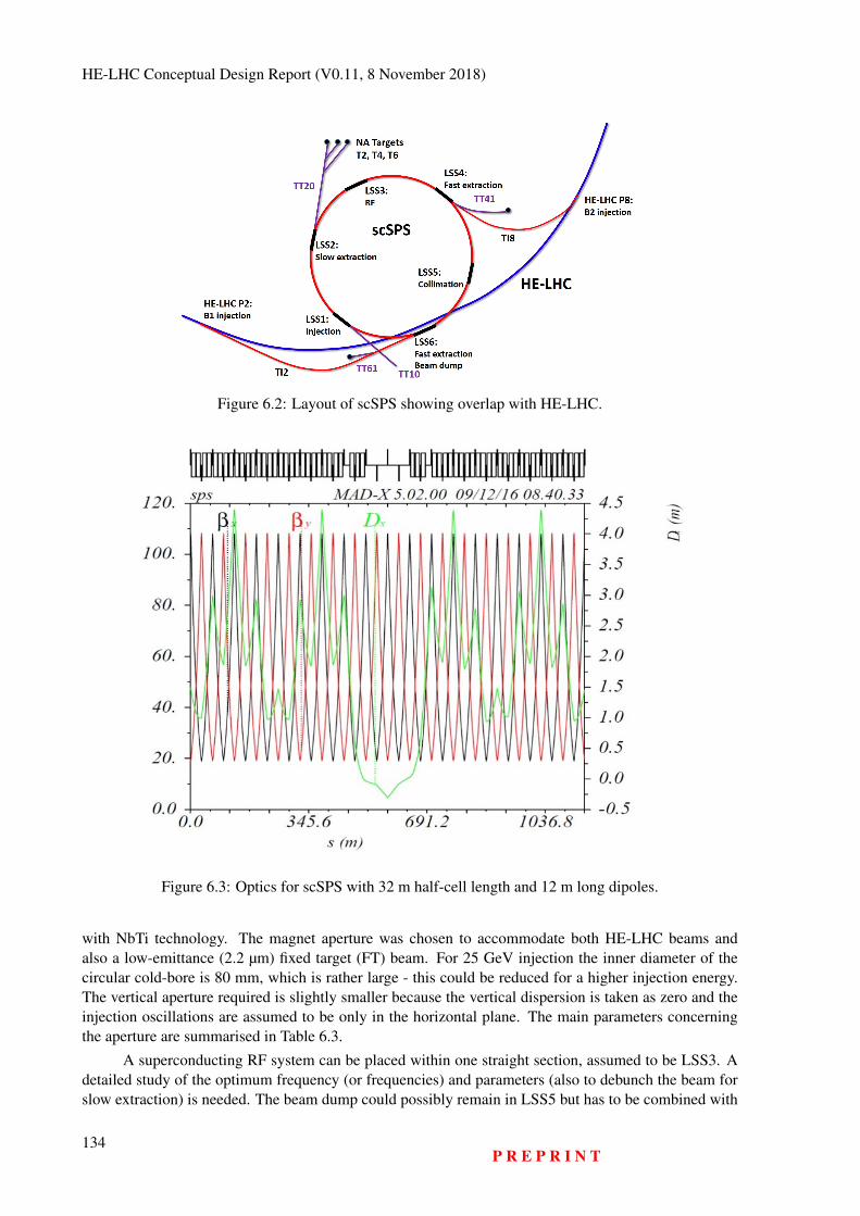
HE-LHC Conceptual Design Report (V0.11, 8 November 2018)
Figure 6.2: Layout of scSPS showing overlap with HE-LHC.
Figure 6.3: Optics for scSPS with 32 m half-cell length and 12 m long dipoles.
with NbTi technology. The magnet aperture was chosen to accommodate both HE-LHC beams andalso a low-emittance (2.2 µm) fixed target (FT) beam. For 25 GeV injection the inner diameter of thecircular cold-bore is 80 mm, which is rather large - this could be reduced for a higher injection energy.The vertical aperture required is slightly smaller because the vertical dispersion is taken as zero and theinjection oscillations are assumed to be only in the horizontal plane. The main parameters concerningthe aperture are summarised in Table 6.3.
A superconducting RF system can be placed within one straight section, assumed to be LSS3. Adetailed study of the optimum frequency (or frequencies) and parameters (also to debunch the beam forslow extraction) is needed. The beam dump could possibly remain in LSS5 but has to be combined with
134P R E P R I N T
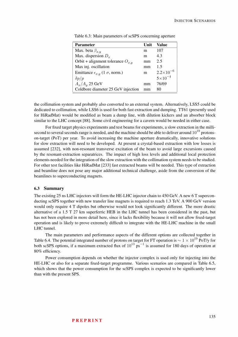
INJECTOR SCENARIOS
Table 6.3: Main parameters of scSPS concerning aperture
Parameter Unit ValueMax. beta βx,y m 107Max. dispersion Dx m 4.3Orbit + alignment tolerance Ox,y mm 2.5Max inj. oscillation mm 1.5Emittance εx,y (1 σ, norm.) m 2.2×10⁻⁶
δp/p 5×10⁻⁴
Ax/Ay 25 GeV mm 76/69Coldbore diameter 25 GeV injection mm 80
the collimation system and probably also converted to an external system. Alternatively, LSS5 could bededicated to collimation, while LSS6 is used for both fast extraction and dumping. TT61 (presently usedfor HiRadMat) would be modified as beam a dump line, with dilution kickers and an absorber blocksimilar to the LHC concept [88]. Some civil engineering for a cavern would be needed in either case.
For fixed target physics experiments and test beams for experiments, a slow extraction in the milli-second to several seconds range is needed, and the machine should be able to deliver around 1019 protons-on-target (PoT) per year. To avoid increasing the machine aperture dramatically, innovative solutionsfor slow extraction will need to be developed. At present a crystal-based extraction with low losses isassumed [232], with non-resonant transverse excitation of the beam to avoid large excursions causedby the resonant-extraction separatrices. The impact of high loss levels and additional local protectionelements needed for the integration of the slow extraction with the collimation system needs to be studied.For other test facilities like HiRadMat [233] fast extracted beams will be needed. This type of extractionand beamline does not pose any major additional technical challenge, aside from the conversion of thebeamlines to superconducting magnets.
6.3 SummaryThe existing 25 ns LHC injectors will form the HE-LHC injector chain to 450 GeV. A new 6 T supercon-ducting scSPS together with new transfer line magnets is required to reach 1.3 TeV. A 900 GeV versionwould only require 4 T dipoles but otherwise would not look significantly different. The more drasticalternative of a 1.5 T 27 km superferric HEB in the LHC tunnel has been considered in the past, buthas not been explored in more detail here, since it lacks flexibility because it will not allow fixed-targetoperation and is likely to prove extremely difficult to integrate with the HE-LHC machine in the smallLHC tunnel.
The main parameters and performance aspects of the different options are collected together inTable 6.4. The potential integrated number of protons on target for FT operation is∼ 1× 10¹⁹ PoT/y forboth scSPS options, if a maximum extracted flux of 1013 ps−1 is assumed for 180 days of operation at80% efficiency.
Power consumption depends on whether the injector complex is used only for injecting into theHE-LHC or also for a separate fixed-target programme. Various scenarios are compared in Table 6.5,which shows that the power consumption for the scSPS complex is expected to be significantly lowerthan with the present SPS.
P R E P R I N T135
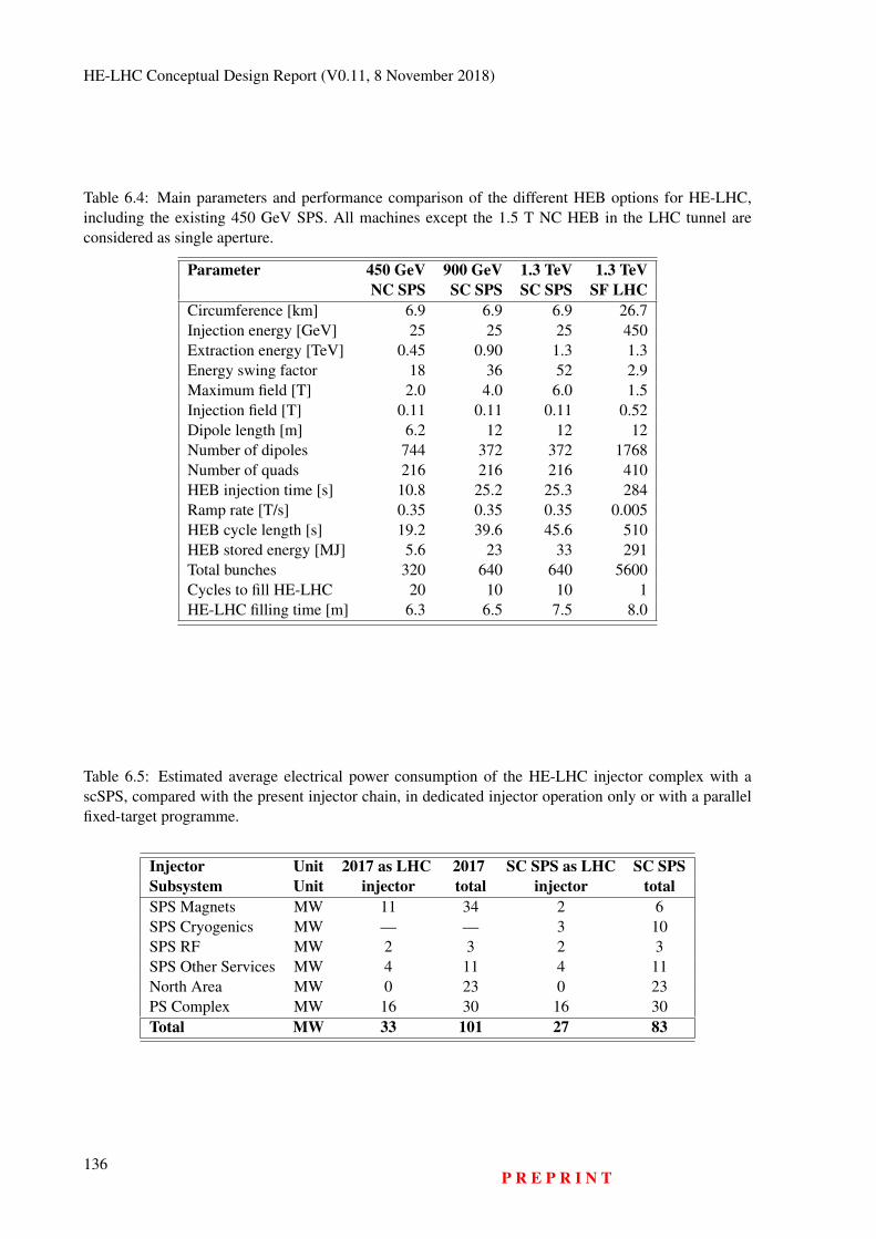
HE-LHC Conceptual Design Report (V0.11, 8 November 2018)
Table 6.4: Main parameters and performance comparison of the different HEB options for HE-LHC,including the existing 450 GeV SPS. All machines except the 1.5 T NC HEB in the LHC tunnel areconsidered as single aperture.
Parameter 450 GeV 900 GeV 1.3 TeV 1.3 TeVNC SPS SC SPS SC SPS SF LHC
Circumference [km] 6.9 6.9 6.9 26.7Injection energy [GeV] 25 25 25 450Extraction energy [TeV] 0.45 0.90 1.3 1.3Energy swing factor 18 36 52 2.9Maximum field [T] 2.0 4.0 6.0 1.5Injection field [T] 0.11 0.11 0.11 0.52Dipole length [m] 6.2 12 12 12Number of dipoles 744 372 372 1768Number of quads 216 216 216 410HEB injection time [s] 10.8 25.2 25.3 284Ramp rate [T/s] 0.35 0.35 0.35 0.005HEB cycle length [s] 19.2 39.6 45.6 510HEB stored energy [MJ] 5.6 23 33 291Total bunches 320 640 640 5600Cycles to fill HE-LHC 20 10 10 1HE-LHC filling time [m] 6.3 6.5 7.5 8.0
Table 6.5: Estimated average electrical power consumption of the HE-LHC injector complex with ascSPS, compared with the present injector chain, in dedicated injector operation only or with a parallelfixed-target programme.
Injector Unit 2017 as LHC 2017 SC SPS as LHC SC SPSSubsystem Unit injector total injector totalSPS Magnets MW 11 34 2 6SPS Cryogenics MW — — 3 10SPS RF MW 2 3 2 3SPS Other Services MW 4 11 4 11North Area MW 0 23 0 23PS Complex MW 16 30 16 30Total MW 33 101 27 83
136P R E P R I N T
Chapter 7
Experiments and Detectors
7.1 Detector Considerations
Table 7.1 relates the collision environment and some key parameters for the different hadron machinesLHC, HL-LHC, HE-LHC and FCC-hh. For the HE-LHC energy of 27 TeV, the total inelastic pp cross-section, multiplicity and average pT of charged particles increase by less than 20% with respect to LHC.The rapidity distribution of benchmark SM objects like b-jets, VBF jets, H→ 4l is slightly increased by≈ 0.3 with respect to LHC. The HE-LHC uses a value of L∗ = 23 m, equal to the LHC and assumesonly minimal changes to the civil engineering infrastructure of the LHC tunnel and caverns. In terms ofacceptance and overall size, the detectors at the HE-LHC therefore relate more to HL-LHC detectors thanto detectors for the FCC-hh, which assume significantly increased instrumentation in the very forwardregion.
The HE-LHC luminosity of L = 16×1034 cm−2s−1 is however, significantly higher than the HL-LHC luminosity. The related pile-up of 500 is about 3.4 times larger than at HL-LHC and about half thenumber at the FCC-hh. It can therefore be assumed, in a first approximation, that detectors at the HE-LHC are ATLAS/CMS type detectors with challenges related to radiation, pile-up, trigger and readoutrate that are closer to the FCC-hh detector concepts. To what extent the magnet systems of ATLAS andCMS might be reused for the HE-LHC will depend on the specific new subdetector concepts and also onthe expected lifetime of these magnets.
The hadron fluence in the innermost silicon layers is, as usual, one of the key challenges forsuch a high luminosity hadron detector. The value is about four times larger than the HL-LHC at thesame radius, and will increase with 1/r2 if the first layer is moved closer to the collision point. Sincethe fluence for the HL-LHC already poses a significant challenge to the Phase-II upgrades of ATLASand CMS, dedicated R&D on radiation hard silicon sensors that can stand hadron fluences in excess of1017 cm−2 for the inner tracking layers is therefore essential.
The increased radiation load is also a concern for the calorimetry. Cryogenic noble liquid calorime-ters, as employed by the ATLAS experiment or silicon calorimeters, as planned in the forward region ofthe CMS Phase-II upgrade, are possible candidates for a detector at the HE-LHC. The rates in the muonsystems are such that one can employ large area gas detectors similar to those used at the LHC.
To deal with the large pile-up of about 500, high precision timing detectors with a resolution of<10 ps, as discussed for the FCC-hh detector, are essential. The total rate of charged tracks is about 4times larger than that of the HL-LHC and about 3 times smaller than that at the FCC-hh. The rate ofhigh energy jets is about 12 times larger than at HL-LHC and 6 times smaller than at the FCC-hh. Thereadout and trigger challenges therefore relate more to the FCC-hh than to the HL-LHC.
As discussed for the FCC-hh reference detector, there is little doubt that the signals from the
137
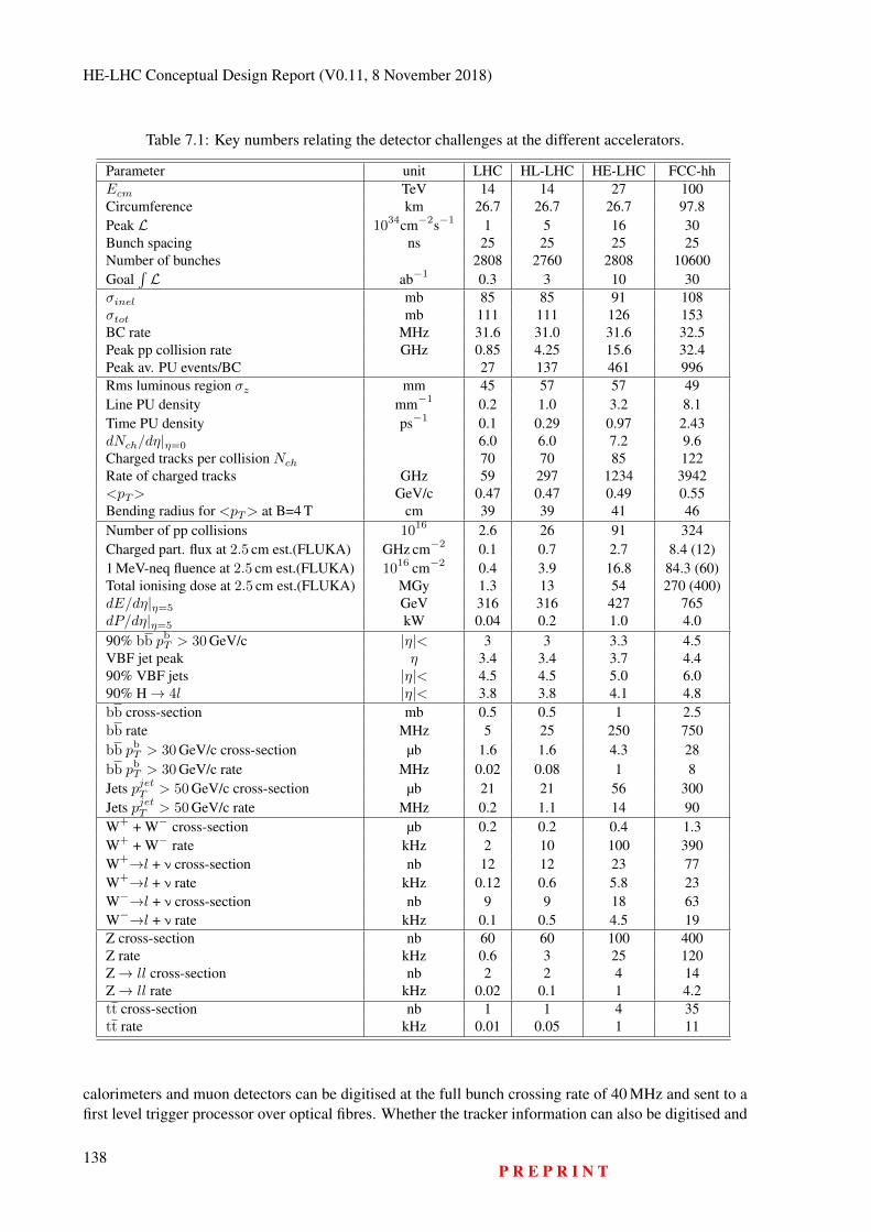
HE-LHC Conceptual Design Report (V0.11, 8 November 2018)
Table 7.1: Key numbers relating the detector challenges at the different accelerators.
Parameter unit LHC HL-LHC HE-LHC FCC-hhEcm TeV 14 14 27 100Circumference km 26.7 26.7 26.7 97.8Peak L 1034cm−2s−1 1 5 16 30Bunch spacing ns 25 25 25 25Number of bunches 2808 2760 2808 10600Goal
∫L ab−1 0.3 3 10 30
σinel mb 85 85 91 108σtot mb 111 111 126 153BC rate MHz 31.6 31.0 31.6 32.5Peak pp collision rate GHz 0.85 4.25 15.6 32.4Peak av. PU events/BC 27 137 461 996Rms luminous region σz mm 45 57 57 49Line PU density mm−1 0.2 1.0 3.2 8.1Time PU density ps−1 0.1 0.29 0.97 2.43dNch/dη|η=0 6.0 6.0 7.2 9.6Charged tracks per collision Nch 70 70 85 122Rate of charged tracks GHz 59 297 1234 3942<pT> GeV/c 0.47 0.47 0.49 0.55Bending radius for <pT> at B=4 T cm 39 39 41 46Number of pp collisions 1016 2.6 26 91 324Charged part. flux at 2.5 cm est.(FLUKA) GHz cm−2 0.1 0.7 2.7 8.4 (12)1 MeV-neq fluence at 2.5 cm est.(FLUKA) 1016 cm−2 0.4 3.9 16.8 84.3 (60)Total ionising dose at 2.5 cm est.(FLUKA) MGy 1.3 13 54 270 (400)dE/dη|η=5 GeV 316 316 427 765dP/dη|η=5 kW 0.04 0.2 1.0 4.090% bb pbT > 30 GeV/c |η|< 3 3 3.3 4.5VBF jet peak η 3.4 3.4 3.7 4.490% VBF jets |η|< 4.5 4.5 5.0 6.090% H→ 4l |η|< 3.8 3.8 4.1 4.8bb cross-section mb 0.5 0.5 1 2.5bb rate MHz 5 25 250 750bb pbT > 30 GeV/c cross-section µb 1.6 1.6 4.3 28bb pbT > 30 GeV/c rate MHz 0.02 0.08 1 8Jets pjetT > 50 GeV/c cross-section µb 21 21 56 300Jets pjetT > 50 GeV/c rate MHz 0.2 1.1 14 90W+ + W− cross-section µb 0.2 0.2 0.4 1.3W+ + W− rate kHz 2 10 100 390W+→l + ν cross-section nb 12 12 23 77W+→l + ν rate kHz 0.12 0.6 5.8 23W−→l + ν cross-section nb 9 9 18 63W−→l + ν rate kHz 0.1 0.5 4.5 19Z cross-section nb 60 60 100 400Z rate kHz 0.6 3 25 120Z→ ll cross-section nb 2 2 4 14Z→ ll rate kHz 0.02 0.1 1 4.2tt cross-section nb 1 1 4 35tt rate kHz 0.01 0.05 1 11
calorimeters and muon detectors can be digitised at the full bunch crossing rate of 40 MHz and sent to afirst level trigger processor over optical fibres. Whether the tracker information can also be digitised and
138P R E P R I N T

EXPERIMENTS AND DETECTORS
read out at 40 MHz or whether a dedicated trigger will have to reduce the tracker readout rate to a fewMHz will depend on the link technology available in the future.
For HE-LHC physics studies, the performance of the ATLAS/CMS detectors for a pile-up of 1 isassumed. It is therefore assumed that there will be an ATLAS/CMS type detector with a rate capabilityand technology for pile-up rejection that allows detector performance equal to the present low pile-upperformance of the LHC detectors.
P R E P R I N T139

HE-LHC Conceptual Design Report (V0.11, 8 November 2018)
140P R E P R I N T
Chapter 8
Safety
8.1 Safety Policy and Regulatory FrameworkThe concept study aims at demonstrating that hazard and risk control for a future hadron collider ispossible with best practices and industrial standards, which are complemented, where necessary, withtechniques specific for a particle accelerator facility. The approach is introduced below by first presentingCERN’s legal context and then the hazard and risk management in place for the existing acceleratorcomplex. The subsequent sections show how occupational health and safety topics are addressed, whichare specific for a particle collider, and how the risks associated with ionising radiation are managed.For the conceptual design, a two-stage process has been chosen: first, a hazard register lists the safetyhazards that will be present at the facility and identifies those, for which standard best practices can beapplied to control the associated risks. Second, a detailed analysis will be carried out, for the remainingsafety risks, to assess the risk levels and to identify mitigation measures.
8.1.1 Legal Context of CERNCERN’s status as international organisation requires that it defines a safety policy in a pro-active andconsensus-based process with the host states (see Art. II 2 de l’accord de statut de 1973 entre le CERNet la France [234]). This approach is applicable for non-standard installations like the accelerators, theexperiments and the technical infrastructure needed to operate these facilities. Where standard infrastruc-ture dominates (e.g. offices, car parks and workshops), CERN ensures uniformity in the safety conditionsacross its sites, taking into account the laws and regulations of the host states and EU regulations and di-rectives. Where uniformity cannot be achieved or where compliance is not required to ensure the properfunctioning of the organisation, a dedicated risk management process is applied, including the planning,implementation and verification of risk mitigation measures.
8.1.2 Hazard Register and Safety Performance Based DesignA systematic collection of safety hazards associated with the construction and operation of the accelera-tor complex is the starting point of the safety assessment. Hazard registers are an established techniquein industry. To compile the register, a process-centred approach has been used [235]. In a first step, a sys-tematic description of the processes during the life cycle of the accelerator facility has been established,based on the Project Breakdown Structure (PBS). Each process is characterised by activities, equipmentand substances used or released. Hazards may emerge from these activities, equipments and substancesat different locations.
As an example, the process of providing electrical power to accelerator magnets is active duringcommissioning and operation of the accelerator. It relies on transformers and power converters (equip-
141
HE-LHC Conceptual Design Report (V0.11, 8 November 2018)
ment) at the surface and in underground locations. This equipment is at the origin of electrical hazards,noise and potential environmental pollution in the case of dispersion of insulating fluids.
It is assumed that the relevant risks associated with the hazards will be mitigated by standard bestpractices, implementing compliance with laws and regulations of the host states, EC regulations anddirectives, international regulations, standards and directives and recommendations from technical orprevention organisms.
Where standard best practices cannot be applied or would affect the proper operation of the or-ganisation, a performance-based design approach is used [236]. It is proposed to use a standard methodlike “Failure Mode, Effects and Criticality Analysis” (FMECA) [237] to identify those risks which re-main unacceptable. From this starting point, the performance based approach is used. In this process,essential safety objectives, such as preservation of human lives or prevention of environmental damage,are defined. The safety performance of design choices is evaluated for different incident scenarios. If theobjectives are met, the design can be retained as mitigation measure.
8.2 Occupational Health and SafetyTwo main hazards are present in underground areas: fire and oxygen deficiency. The results of thestudies [238, 239] are summarised in the following sections. The agreed safety objectives for these twohazards are listed in Table 8.1.
Table 8.1: Safety objectives in the design-oriented study.
Life Safety EnvironmentalProtection
PropertyProtection
Continuity ofOperation
Safety of authorisedoccupants (O1)
Limited release ofpollutants to air (O4)
Continuity of essentialservices (O6)
Limited downtime(O9)
Safe evacuation orstaging of injuredoccupants (O2)
Limited release ofpollutants to water
(O5)
Incident must notcause further incidents
(O7)Safe intervention ofrescue teams (O3)
Limited property loss(O8)
To create safe zones along the entire perimeter of the particle collider, smoke and fire resistantcompartment walls are recommended to be installed every four accelerator lattice cells, each 548 m.Under normal conditions, their doors are open. The ventilation system is based on a pull-push schemebetween adjacent shafts to create a longitudinal unidirectional flow. Smoke and ODH detectors initiatelocalised mitigation measures, like the closure of the doors. A dedicated 350 mm diameter extraction ducttraverses all compartments and can extract smoke or helium. The extraction for each compartment can becontrolled individually. It is planned to have a fire fighting pipeline with an outlet at each compartmentdoor.
8.2.1 Fire HazardThe most critical phases for a fire hazard are (1) the operation with beam, (2) a long shut-down and(3) a technical stop. During operation, all electrical systems are powered and potential ignition sources.During other periods, personnel is present who may inadvertently cause a fire, e.g. during welding. Table8.2 shows the three fire scenarios studied.
Following the performance based design (PBD) methodology, the current LHC tunnel equippedwith the planned safety measures was challenged with three different accidental fire scenarios repre-senting credible fires in the HE-LHC underground tunnel structure. For consistency, the fire scenarios
142P R E P R I N T
SAFETY
Table 8.2: Fire scenarios in the design-oriented safety study.
Scenario Description Ignition sourceFire 1 Cable tray fire Electrical fireFire 2 Cable drum fire Hot workFire 3 Transport vehicle fire Battery malfunction
considered were the same as those considered for FCC-hh [240].
Only the life safety goal for occupants was evaluated during this initial study. For the sake of con-sistency, the same performance criteria used for the FCC-hh study were set to ensure tenability limits forthe evacuees. These criteria comprised incident heat flux, temperature, visibility and toxicant exposureaccounted for by means of fractional effective dose (FED).
Upon fire detection, the compartmentalisation doors delimiting the fire compartment and the adja-cent ones (i.e. four doors) will shut and the smoke/Helium extraction duct dampers will open exclusivelyin the fire compartment to create maximum extraction flow.
The smoke/helium extraction duct (always kept at a pressure below normal to optimise the re-action time) will start extracting some smoke and creating a pressure cascade to reinforce smoke con-finement. For the rest of the tunnel, air will be extracted via both shafts, maintaining evacuation pathsover-pressured with respect to the fire compartment and clear from smoke.
This strategy was evaluated within the fire compartment by means of CFD simulations of the threeaccidental scenarios investigated. The simulation program is the Fire Dynamics Simulator FDS v. 6[241]. The pre-movement time and walking speed were defined according to standard recommendations[242] (British Standard PD 7974-6) and were further improved by adding some degree of uncertainty.The results showed that the heat flux, temperature and FED values to which evacuees are exposed arewell within the acceptable thresholds stated in the performance criteria. However, for a single evacuationlocation visibility is locally reduced to below 10 m at 2 m height. The stratification is still maintainedand visibility is unimpeded at 0.5 m height.
Based on the outcome of the simulations, it can be stated that the current design meets the lifesafety objective for occupants in case of fire. However, there is a very limited safety margin and it isstrongly recommended that additional safety measures aimed to increase the robustness of the designshould be explored. The remaining safety objectives are to be evaluated at a later stage.
8.2.2 Oxygen Deficiency Hazard (ODH)The scenario considered for the ODH study was an accidental and uncontrolled release of helium intothe LHC tunnel. It was determined that the most critical phases of the project’s life-cycle are during thecommissioning and maintenance phases, hence the evaluation studies took this into account. Based onthe current access restrictions in the LHC for operational periods where large helium release flows cannotbe excluded, it is assumed that similar measures would be in place during the life-cycle of the HE-LHC.Therefore, the accidental scenario chosen for the analysis was 340 g/s release of gaseous helium into theLHC tunnel.
The evaluation of these studies linked to the cryogenic hazards were based on an initial safetyassessment made for the ‘Release of Gaseous Helium in Tunnels’ [243]. The major change is linkedto magnet technology and the requirement to have compartment walls in the tunnel every 548 m. Theobjective of the study is to determine whether an accidental 340 g/s release produces a helium layerheight at the ceiling of the tunnel such that it would prevent occupants from evacuating.
A helium release is localised within one compartment of 548 m length. The compartment doorswill remain open during a helium release. Gaseous helium rapidly warms up and rises to the compartment
P R E P R I N T143
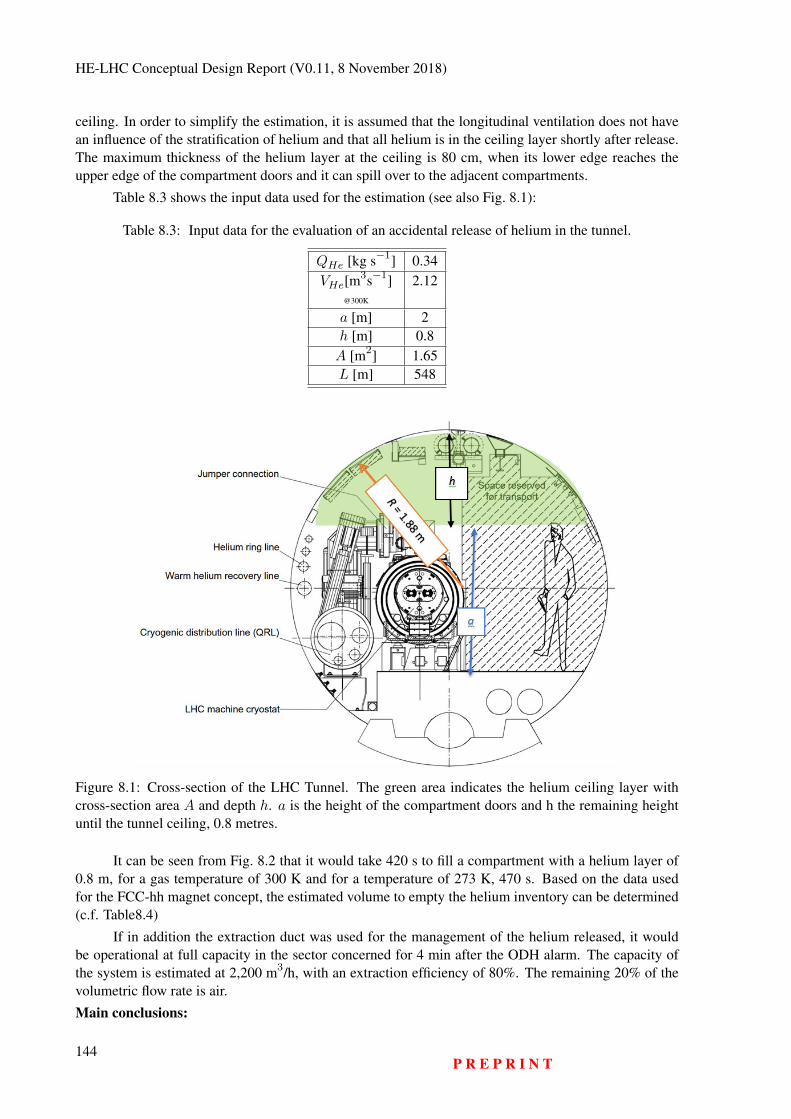
HE-LHC Conceptual Design Report (V0.11, 8 November 2018)
ceiling. In order to simplify the estimation, it is assumed that the longitudinal ventilation does not havean influence of the stratification of helium and that all helium is in the ceiling layer shortly after release.The maximum thickness of the helium layer at the ceiling is 80 cm, when its lower edge reaches theupper edge of the compartment doors and it can spill over to the adjacent compartments.
Table 8.3 shows the input data used for the estimation (see also Fig. 8.1):
Table 8.3: Input data for the evaluation of an accidental release of helium in the tunnel.
QHe [kg s−1] 0.34VHe[m
3s−1] 2.12@300K
a [m] 2h [m] 0.8A [m2] 1.65L [m] 548
Figure 8.1: Cross-section of the LHC Tunnel. The green area indicates the helium ceiling layer withcross-section area A and depth h. a is the height of the compartment doors and h the remaining heightuntil the tunnel ceiling, 0.8 metres.
It can be seen from Fig. 8.2 that it would take 420 s to fill a compartment with a helium layer of0.8 m, for a gas temperature of 300 K and for a temperature of 273 K, 470 s. Based on the data usedfor the FCC-hh magnet concept, the estimated volume to empty the helium inventory can be determined(c.f. Table8.4)
If in addition the extraction duct was used for the management of the helium released, it wouldbe operational at full capacity in the sector concerned for 4 min after the ODH alarm. The capacity ofthe system is estimated at 2,200 m3/h, with an extraction efficiency of 80%. The remaining 20% of thevolumetric flow rate is air.
Main conclusions:
144P R E P R I N T
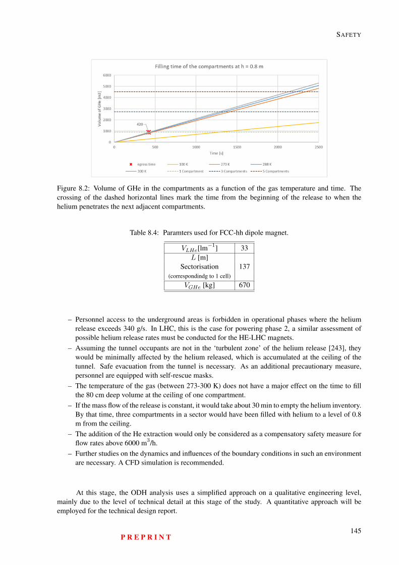
SAFETY
Figure 8.2: Volume of GHe in the compartments as a function of the gas temperature and time. Thecrossing of the dashed horizontal lines mark the time from the beginning of the release to when thehelium penetrates the next adjacent compartments.
Table 8.4: Paramters used for FCC-hh dipole magnet.
VLHe[lm−1] 33
L [m]Sectorisation 137
(correspondindg to 1 cell)
VGHe [kg] 670
– Personnel access to the underground areas is forbidden in operational phases where the heliumrelease exceeds 340 g/s. In LHC, this is the case for powering phase 2, a similar assessment ofpossible helium release rates must be conducted for the HE-LHC magnets.
– Assuming the tunnel occupants are not in the ‘turbulent zone’ of the helium release [243], theywould be minimally affected by the helium released, which is accumulated at the ceiling of thetunnel. Safe evacuation from the tunnel is necessary. As an additional precautionary measure,personnel are equipped with self-rescue masks.
– The temperature of the gas (between 273-300 K) does not have a major effect on the time to fillthe 80 cm deep volume at the ceiling of one compartment.
– If the mass flow of the release is constant, it would take about 30 min to empty the helium inventory.By that time, three compartments in a sector would have been filled with helium to a level of 0.8m from the ceiling.
– The addition of the He extraction would only be considered as a compensatory safety measure forflow rates above 6000 m3/h.
– Further studies on the dynamics and influences of the boundary conditions in such an environmentare necessary. A CFD simulation is recommended.
At this stage, the ODH analysis uses a simplified approach on a qualitative engineering level,mainly due to the level of technical detail at this stage of the study. A quantitative approach will beemployed for the technical design report.
P R E P R I N T145
HE-LHC Conceptual Design Report (V0.11, 8 November 2018)
8.3 Radiation ProtectionFor the mitigation of risks associated with ionising radiation, the standard prescriptive methods of theexisting CERN radiation protection rules and procedures have been used. Risks resulting from ionisingradiation must be analysed from a very early design phase onwards and mitigation approaches must bedeveloped. Design constraints will ensure that the doses received by personnel working on the sitesas well as the public will remain below regulatory limits CodeSante2016,LRaP-2017 under all opera-tion conditions. A reliable and continuously operating radiation monitoring system will therefore be anessential part of the system implementing risk control measures.
The HE-LHC will be comparable in terms of radiological hazards to the LHC after its high lumi-nosity upgrade. These are reliable sources of experience to take into account when planning the radiationprotection measures during the design phase. The main difference for the HE-LHC compared to the HL-LHC is the higher beam energy which will eventually lead to higher activation levels in some sections ofthe accelerator and experiments.
Radiation protection is concerned with two aspects: protection of personnel operating and main-taining the installations and the potential radiological environmental impact. The second topic is ad-dressed in Section 10.2.1. To enable the assessment of the potential radiological risks to the personnelworking on the sites, the radiological hazards are classified by their sources: (1) particle beam operation,(2) activated solids, liquids and gases.
Unlike the FCC, which will be installed in an entirely new tunnel, the HE-LHC will be housedin a modified version of the existing LHC tunnel and infrastructure. As parts of the LHC tunnel will beradioactive, dismantling, civil engineering and installation works in the tunnel will require specific at-tention and planning. Intervention techniques and waste management must be adapted to the radioactiveenvironment. Standard operating procedures will be sufficient to cope with these risks.
8.3.1 Particle Beam Operation
Radiation hazards from high energy particle beams arise from their interaction with matter and otherparticles. Shielding protects personnel by absorbing the primary radiation and the subsequently generatedstray radiation. An access safety and control system must prevent people from accessing hazardous areasduring beam operation.
The HE-LHC will be located in the current LHC tunnel largely making use of the same infras-tructure. LHC is currently operated with access to underground areas prohibited, with exception of theexperiment service caverns. Applied to the HE-LHC these access conditions will be sufficient to protectagainst undue stray radiation levels from particle beam operation in accessible areas.
The underground infrastructure (mainly service caverns of the experiments) currently accessiblewill require a detailed reassessment to confirm the exact delimitation between radiation and non-radiationareas, and accessible and non-accessible radiation areas during beam operation. This analysis will takeinto account the energy and intensity increase, as well as the design objectives adopted in terms of dosesmainly for incident scenarios.
The only locations where radiation can possibly stream to the surface are at the existing shaftsabove the experiments. They can be equipped with additional top shielding if required. However, it isexpected that no additional top shielding compared to the current situation at the LHC is required, giventhe scaled shielding effect of the experiments at the HE-LHC.
8.3.2 Activation of Solids
Activation of solids represents a potential hazard to personnel through exposure to gamma radiationduring interventions inside the accelerator tunnel such as in-situ maintenance or handling of radioactiveparts. The radiation levels differ considerably amongst the various sectors of the accelerator and depend
146P R E P R I N T
SAFETY
on the type of beam operation and on the time that has passed since the machine was stopped. Locationsclose to the interaction points, the beam cleaning insertions as well as the final beam absorbers will ex-hibit the highest radiation levels from activation, exceeding those at analogous locations in the LHC. Anaverage increase by a factor 4 of induced radioactivity concentrations and residual dose rates is currentlyassumed as a result of the energy and intensity increase compared to the nominal LHC operation. Op-timisation of activation levels can be achieved through an appropriate choice of materials in the designphase of the new accelerator components.
The main arc sections of the LHC are exposed to very low radiation levels. The expected increasefor HE-LHC will remain low enough to apply current maintenance intervals and techniques. Further useof robotic solutions for maintenance and other interventions in high radiation areas are already envisagedto reduce the exposure of personnel for the HL-LHC. These techniques will become more predominant atthe HE-LHC, especially in the sections next to the high luminosity interaction points and the collimationregions. It is expected that there will be a wider availability of robotic technology by the time of HE-LHCoperation.
Activated materials are routinely removed from the accelerator tunnel and experiment caverns formaintenance and for disposal. The operations expected for the HE-LHC will generate a similar amountof materials to that currently handled within the existing infrastructure at CERN [244].
Corrosion and machining of activated materials can produce dispersed activated solids in the ac-celerator and workshop areas. Experience shows that this does not lead to relevant radiation risks andtherefore standard procedures apply.
8.3.3 Activated or Contaminated LiquidsInfiltration water or leakage water from closed demineralised water circuits, raw water or cooling circuitswill be collected by the tunnel drainage system. The water will be pumped to the surface sites to bereleased.
The demineralised water filtering units collect and concentrate radioactive particles and will betreated through standard procedures.
Ventilation cooling units for the tunnel and experiment areas may concentrate air-borne radioac-tivity in their condensates, mainly in the form of tritiated water. This liquid waste water will be collectedand treated according to standard procedures.
The activation of cryogenic liquid helium which is used in the superconducting circuits, resultsin the production of small amounts of tritium. Sufficient storage capacities for potentially contaminatedhelium are planned for the various sites. Whereas not all helium in use for cooling the LHC magnets andcavities can be currently stored at CERN, sufficient capacities will be installed for the HE-LHC.
8.3.4 Activated or Radioactive Gases and Radioactive AerosolsAir in the accelerator and experiment areas will become radioactive during beam operation. The mainLHC ventilation system will be renewed and built to operate in full or partial recycling mode to limitreleases to the environment. While the current ventilation scheme at LHC is compatible with the ap-plicable dose constraints, the energy and intensity increase for HE-LHC and the required safety marginsuggest that implementing an air recycling system is necessary. For access, the areas will be sufficientlyventilated with fresh air beforehand to avoid undue exposure of the intervening personnel. By experi-ence, potential outgassing from activated concrete or radon decay products will only be present in smallconcentrations as they are continuously removed by the filters in the ventilation system. Dust activationand airborne corrosion products do not represent relevant sources of exposure to intervening personnel.Aerosols are continuously removed by the air treatment systems.
P R E P R I N T147

HE-LHC Conceptual Design Report (V0.11, 8 November 2018)
148P R E P R I N T
Chapter 9
Energy Efficiency
9.1 Requirements and Design Considerations
Energy efficiency is a topic which is high on the societal agenda in general and must consequently also bea core value of any future research facility, especially energy-intensive facilities like particle accelerators.It concerns the availability and cost of electricity, the reduction of climate-relevant emissions, and otherside-effects linked to energy production, transmission and conversion. Operating the HE-LHC in anenergy efficient way will enhance its public acceptance. Moreover, the HE-LHC is an opportunity todrive the evolution of energy efficient technologies leading to socio-economic benefits. A sign of theimportance of the topic is the “Energy for Sustainable Science” workshop series [245] established severalyears ago. Concerted efforts are being made in the framework of the EuCard2 Project [246] (WorkPackage 3 - Energy efficiency of particle accelerators [247]) and the ARIES Project [248] in the ECHorizon 2020 Research and Innovation Programme. An overview of activities in view of greater energyefficiency of particle accelerators can be found in [249].
Energy-efficient approaches can be categorised in three levels. The first level, with the highestpriority, is to consume less energy by making appropriate design choices. For the HE-LHC, the use ofsuperconducting magnets is an unavoidable choice. These do not only provide a very high field of 16 T,but their combined energy consumption (magnet powering, cryogenics) is also dramatically lower thanit would be for a hypothetical collider with the same beam energy, based on normal conducting magnetswith a dipole field around 2 T. The second level aims at using energy more efficiently while providingthe same level of service or performance. An example is the use of high-efficiency klystrons, such asthose presently under development. Finally, recovering and re-using energy for other purposes, ranksthird. A typical example is to recuperate waste heat from cooling circuits, using it within the researchinfrastructure and feeding it into an energy storage system from which it can be used later for districtheating purposes.
Applying fine-grained monitoring of energy use will help to raise energy-awareness, control thepeak power and energy losses and allow better predictions of energy use to be made. All equipmentor facilities not currently in use will be switched off or ramped down. Any new surface buildings willbe constructed to follow high environmental standards, bearing in mind that by far the dominant shareof the energy consumption comes from the operation of the accelerator. As far as possible, electricalenergy will be purchased from renewable sources. Generally, it should be noted that reconciling thedemand for highest performance of the facility over extended running periods with sustainability andreasonable/acceptable energy use is not a simple task. Experts specialising in matters of energy efficiencyor energy saving will be consulted to devise a comprehensive and coherent concept from the outset.
149
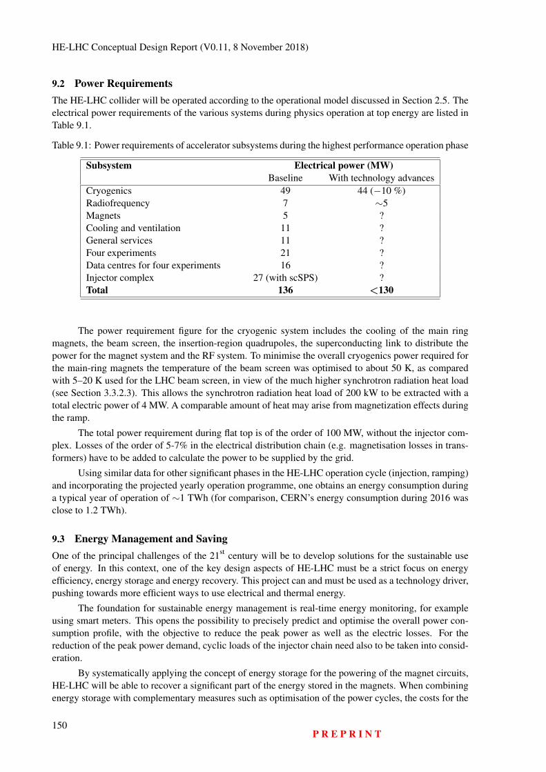
HE-LHC Conceptual Design Report (V0.11, 8 November 2018)
9.2 Power RequirementsThe HE-LHC collider will be operated according to the operational model discussed in Section 2.5. Theelectrical power requirements of the various systems during physics operation at top energy are listed inTable 9.1.
Table 9.1: Power requirements of accelerator subsystems during the highest performance operation phase
Subsystem Electrical power (MW)Baseline With technology advances
Cryogenics 49 44 (−10 %)Radiofrequency 7 ∼5Magnets 5 ?Cooling and ventilation 11 ?General services 11 ?Four experiments 21 ?Data centres for four experiments 16 ?Injector complex 27 (with scSPS) ?Total 136 <130
The power requirement figure for the cryogenic system includes the cooling of the main ringmagnets, the beam screen, the insertion-region quadrupoles, the superconducting link to distribute thepower for the magnet system and the RF system. To minimise the overall cryogenics power required forthe main-ring magnets the temperature of the beam screen was optimised to about 50 K, as comparedwith 5–20 K used for the LHC beam screen, in view of the much higher synchrotron radiation heat load(see Section 3.3.2.3). This allows the synchrotron radiation heat load of 200 kW to be extracted with atotal electric power of 4 MW. A comparable amount of heat may arise from magnetization effects duringthe ramp.
The total power requirement during flat top is of the order of 100 MW, without the injector com-plex. Losses of the order of 5-7% in the electrical distribution chain (e.g. magnetisation losses in trans-formers) have to be added to calculate the power to be supplied by the grid.
Using similar data for other significant phases in the HE-LHC operation cycle (injection, ramping)and incorporating the projected yearly operation programme, one obtains an energy consumption duringa typical year of operation of ∼1 TWh (for comparison, CERN’s energy consumption during 2016 wasclose to 1.2 TWh).
9.3 Energy Management and SavingOne of the principal challenges of the 21st century will be to develop solutions for the sustainable useof energy. In this context, one of the key design aspects of HE-LHC must be a strict focus on energyefficiency, energy storage and energy recovery. This project can and must be used as a technology driver,pushing towards more efficient ways to use electrical and thermal energy.
The foundation for sustainable energy management is real-time energy monitoring, for exampleusing smart meters. This opens the possibility to precisely predict and optimise the overall power con-sumption profile, with the objective to reduce the peak power as well as the electric losses. For thereduction of the peak power demand, cyclic loads of the injector chain need also to be taken into consid-eration.
By systematically applying the concept of energy storage for the powering of the magnet circuits,HE-LHC will be able to recover a significant part of the energy stored in the magnets. When combiningenergy storage with complementary measures such as optimisation of the power cycles, the costs for the
150P R E P R I N T
ENERGY EFFICIENCY
electrical infrastructure as well as for electrical losses can be greatly reduced.
Electricity transmission over long distances and voltage step-down or step-up leads to powerlosses. The overall losses of a conventional transmission and distribution network range between 5%and 10%. Power line losses are resistive losses by Joule effect. Transformers contribute with load losseswhich will vary according to the load on transformer and no-load losses which are caused by the magne-tizing current needed to energize the transformers and are steady losses. The proposed baseline transmis-sion and distribution scheme also considers providing the required level of availability, maintainabilityand operability from the early concept phase onwards. As an example, where needed, two 66/18 kVtransformers are operated on access points in parallel, each at a nominal load level of 50%. Such aconfiguration responds to the above mentioned, non-functional requirements, but it is not optimized forenergy efficiency. Alternative schemes aiming at improving the overall efficiency of the transmission anddistribution network while maintaining the required level of availability, maintainability and operabilityneed therefore to be studied. Industrial partners will lead the development, potentially demonstrating thetechnology in a pilot at CERN’s LHC so that a system at acceptable cost and with the needed reliabilitylevel can be obtained them from market suppliers when needed.
The power demand is particularly high during ramping-up of magnets. With the proposed power-ing layout (see Section 3.8) and the baseline ramp-up time of 20 minutes, the main dipoles would requirea peak power of 70 MW. This value can be reduced by having a different ramp shape, ramping the cir-cuits up with constant power instead of constant voltage. Extending the time of the ramp is another wayto reduce the peak power. For instance, using a constant-power ramp over 30 minutes, the peak powerfor the main dipole circuits will be reduced to 25 MW.
If the power for ramping up the collider were to be drawn from the external supply, the electri-cal distribution would need to be significantly reinforced. Instead of drawing the power directly fromthe grid, it could also be taken from local storage, typically in the form of batteries, high-voltage DCcapacitors, or a combination of different technologies. Examples of this have already demonstrated andare begin gradually implemented in the new power converter systems of PS and PSB at CERN. Thishas the advantage that the energy stored in the magnets can be recovered and fed back into the storagemedia, from where it can be drawn again during the next ramp. 1232 magnets each returning 37 MJ percycle can provide additional power of ∼38 MW to significantly reduce the peak power needed duringthe next acceleration cycle. Depending on where the local energy storage is located, this approach wouldalso reduce the cross section of the cables supplying the power converters and the dimensions of thesub-stations and transformers.
The RF system energy efficiency can be improved by optimising the electrical to RF power con-version efficiency and the cryogenic refrigeration system energy consumption. With new bunching tech-nologies for high efficiency klystrons, efficiencies are expected to raise from 65 % to above 80 %. Theseimprovements reduce the water cooling requirements by the same amount. The cryogenic losses can bereduced by improving the static and dynamic losses of the cavity cryomodule. The static losses in an op-timised cryomodule are expected to be up to 40 % lower than in the LHC. Recent findings on alternativecavity materials promise real progress in cutting the dynamic losses [132].
A future particle collider will use a cryogenics system based on a neon-helium mixture (a.k.a.Nelium), which leads to electrical energy savings of about 16% with respect to the LHC-type infrastruc-ture. Further electrical power savings leading to about 20% of savings with respect to the LHC can beachieved by improving the efficiency of the 40-60 K cooling stage. This includes improvements in thetechnology of turbo-expanders and recovering energy from the system. Additional improvements may beachieved with centrifugal compressors on the helium cycle. However, such developments are on a longtime-scale and are, therefore, not considered at this stage. The initial savings of 20 % of the HE-LHCcryogenics system consumption correspond to about one third of CERN’s electricity expenditure today.
P R E P R I N T151
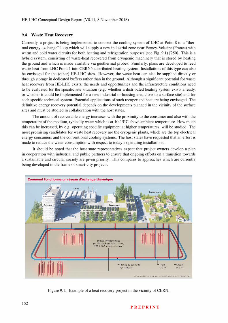
HE-LHC Conceptual Design Report (V0.11, 8 November 2018)
9.4 Waste Heat Recovery
Currently, a project is being implemented to connect the cooling system of LHC at Point 8 to a “ther-mal energy exchange” loop which will supply a new industrial zone near Ferney-Voltaire (France) withwarm and cold water circuits for both heating and refrigeration purposes (see Fig. 9.1) [250]. This is ahybrid system, consisting of waste-heat recovered from cryogenic machinery that is stored by heatingthe ground and which is made available via geothermal probes. Similarly, plans are developed to feedwaste heat from LHC Point 1 into CERN’s distributed heating system. Installations of this type can alsobe envisaged for the (other) HE-LHC sites. However, the waste heat can also be supplied directly orthrough storage in dedicated buffers rather than in the ground. Although a significant potential for wasteheat recovery from HE-LHC exists, the needs and opportunities and the infrastructure conditions needto be evaluated for the specific site situation (e.g. whether a distributed heating system exists already,or whether it could be implemented for a new industrial or housing area close to a surface site) and foreach specific technical system. Potential applications of such recuperated heat are being envisaged. Thedefinitive energy recovery potential depends on the developments planned in the vicinity of the surfacesites and must be studied in collaboration with the host states.
The amount of recoverable energy increases with the proximity to the consumer and also with thetemperature of the medium, typically water which is at 10-15°C above ambient temperature. How muchthis can be increased, by e.g. operating specific equipment at higher temperatures, will be studied. Themost promising candidates for waste heat recovery are the cryogenic plants, which are the top electricalenergy consumers and the conventional cooling systems. The host states have requested that an effort ismade to reduce the water consumption with respect to today’s operating installations.
It should be noted that the host state representatives expect that project owners develop a planin cooperation with industrial and public partners to ensure that ongoing efforts on a transition towardsa sustainable and circular society are given priority. This compares to approaches which are currentlybeing developed in the frame of smart-city projects.
Figure 9.1: Example of a heat recovery project in the vicinity of CERN.
152P R E P R I N T
ENERGY EFFICIENCY
Another potential area of interest is the return to the supplier of cooling water after use for subse-quent heating purposes. GeniLac1, a 280 MCHF investment project close to the United Nations district(Geneva, Switzerland) with a total cooling capacity of 280 MW, can be further investigated in view ofan optimised overall energy balance. The cooling water could also be transported in the tunnel to re-mote points. This study should take the distances from potential consumers and the evolution of urbanareas up to the middle of the century into consideration. Potential consumers include, first of all, publicinstitutions such as healthcare providers, schools, public buildings and industrial zones. Next, innova-tion potentials such as indoor farming, health care centres and support for private district heating can beconsidered.
A third concept involves a step increase of the water temperature in the outer circuits such thatthe supplied heat becomes an interesting resource for industries such as chemical and food processing.Systems for vapour generation stepping up from 25°C quickly become economically feasible [251], buta client needs to be available close to the heat production source and willing to engage in a project thatdoes not require the research infrastructure to function as a reliable energy supplier.
Eventually, direct power generation from waste heat can also be envisaged. Today, the effec-tiveness of such systems is still low, in the few percent range, but industrial interest [252] in view ofincreasing the efficiency of industrial plants is driving R&D activities, for instance via ORC [253] de-vices. Even modest gains from converting heat into electrical or mechanical energy can be beneficial fora large-scale research facility in view of technological advances on a time scale of twenty years for asystem that generates of the order of 100 MW of heat.
1https://www.genie.ch/project/h/genilac-une-innovation-energetique-majeure-et-durable-pour-geneve.html
P R E P R I N T153

HE-LHC Conceptual Design Report (V0.11, 8 November 2018)
154P R E P R I N T
Chapter 10
Environment
10.1 Requirements and Approach Considerations10.1.1 Legal Requirements
For the correct operation of CERN’s facilities, its status as an international organisation requires thatit establishes the requirements and constraints concerning the management of its environmental impactin a pro-active and consensus-based process with the host state on whose territory the installation lies(see Art. II 2 of “L’accord de statut de 1972 entre le CERN et la France” [254]). Where there isstandard infrastructure on the surface sites (e.g. office buildings, car parks, ordinary workshops), CERNimplements the national laws and regulations that apply at the location where the facility is located (seealso “Art. II Convention entre la France et la Suisse de 1965” [255]). A specific process is necessaryfor the non-standard installations like the accelerators, the experiments and the technical infrastructureneeded to operate these facilities. Different rules apply to a project with underground infrastructurewhich crosses the international border and which has surface sites in both Switzerland and France:
Underground infrastructure: In Switzerland, underground volumes below a depth that is con-sidered useful for the land owner is not subject to the acquisition of rights-of-way and the law applying toprivate property. A communication from the Département Fédéral des Affaires Étrangères (DFAE) on 16July 1982, informs CERN that it is exempt from right-of-way acquisition regulations for the LEP/LHCunderground structures. In France, land ownership extends to the centre of the earth. Therefore eithera process to acquire the underground volumes or to acquire the rights-of-way needs to take place. Forboth host states, CERN remains liable for any potential impact on the population and the environmentresulting from the construction and operation of underground and surface installations.
Surface sites: The land plots for surface sites need to be acquired or leased in both host countries.According to a preliminary study carried out with an environmental impact assessment contractor [256],in Switzerland, an environmental impact assessment needs to be performed when new car parks withmore than 500 places are constructed or if per year more than 10’000 t of excavation material are pro-cessed on Swiss territory with the purpose to re-use that material [257]. The “Ordonnance relativeá l’étude de l’impact sur l’environnement (OEIE, Oct. 1988 and 2016)” and the manual “L’étude del’impact sur l’environnement (EIE) (2009)” [258] define the scope and contents of the assessment. InFrance, a recent law revision1 introduced a new environmental impact management process [259]. Thisnew process explicitly requires a public consultation process on the scope, objectives, socio-economicpotentials and the impacts on the development of the territory that needs to take place well before aspecific technical design is developed and before a decision to construct is taken2. The host countries re-
1https://www.ecologique-solidaire.gouv.fr/levaluation-environnementale2See also Art. L121-15-1 of law 2018-148 of 2 March 2018
155
HE-LHC Conceptual Design Report (V0.11, 8 November 2018)
quire an early and continuous involvement of the population in the project development and constructionpreparation phases that goes beyond information exchange. It calls for an active participation, givingpeople the possibility to contribute in well-defined and limited ways in shaping the project and in par-ticular in developing the potential for added value. Consequently, France and Switzerland require thatthe initial assessment process is carried out from the early design phase onwards, followed by regularreviews of the effectiveness of the mitigation measures and assessment of residual or new impacts whichbecome apparent during the construction and operation phases.
Both host states have regulations and laws concerning the continuous assessment and limitation ofenvironmental impact for a variety of different topics. While the processes comprise very similar topics,the organisation of the information and the reporting templates are different for the two host states. InSwitzerland the impact study may be limited to certain topics depending on the project needs, whereas inFrance all topics need to be discussed. In Switzerland the reporting is topically structured and in Francethe reporting is chronological across the entire project life cycle.
Since the project is international in character, the Espoo agreement applies [260]. CERN hasto ensure that both host states are informed about the effects of any new infrastructure project in theircountry and the effects on the neighbouring countries. This includes for instance the use of energy,consumption of water, traffic and the management of waste across the borders.
10.1.2 Environmental Compatibility Management Concept
The international nature of the project and the similarity of the surface points suggest a uniform andstreamlined framework to carry out an environmental impact assessment across both host states. Thisapproach splits the project into locations (e.g. underground structure, individual surface points, associ-ated infrastructures), topics relevant for the impact assessment (e.g. water, air, noise) and the life cyclephases of the project (e.g. construction, operation, maintenance and retirement). Different requirementsand constraints apply to the various locations and phases. For some it may be necessary to meet thestandard national guidelines of the relevant host state or, for some particular installations, the guidelinesneed to be agreed between CERN and the host state on a case-by-case basis.
It is planned to have a central, uniform platform to manage the analysis, the assessment of proposedmitigation measures, the follow up of the effectiveness of mitigation measures and the analysis of theresidual impact. This platform will permit the extraction of information according to the specific needsof the individual host states. Specialised companies and software solutions exist and should be usedwhenever possible (e.g. Envigo by eon+, see Fig. 10.1). A market survey and competitive selectionprocess should be performed in cooperation with the host state partners in order to ensure that a suitableset of experts and tools are selected for this process. It is considered good practice in Switzerland thatthe owner of a large-scale project delivers a "Notice d’Impact sur l’Environement (NIE)", which is morecomprehensive than the minimum required environmental impact assessment. The uniform frameworkmentioned here permits this approach.
The need to perform the environmental impact assessment and management process before a deci-sion to construct is made, calls for the preparation of the assessment framework with the help of experi-enced consultants and the host state authorities in the years 2018 - 2020. Given some basic infrastructure,consultants and authority partners who know the project vision and goals can work with the scientificand engineering team until the design has reached maturity by 2023. By this time, CERN must havereached consensus with the authorities and the population that permits the formal initiation of a publicconsultation process as required in both host states. The process is considered lengthy in both countriesand is expected to require a few iterations. The goal is to obtain clearance to submit a request for con-struction permits by 2026, i.e. before an international consortium (e.g. the CERN member states or aninternational consortium bound by a memorandum, a letter of intent or a similar type of collaborationagreement) takes a formal decision to build the facility.
156P R E P R I N T
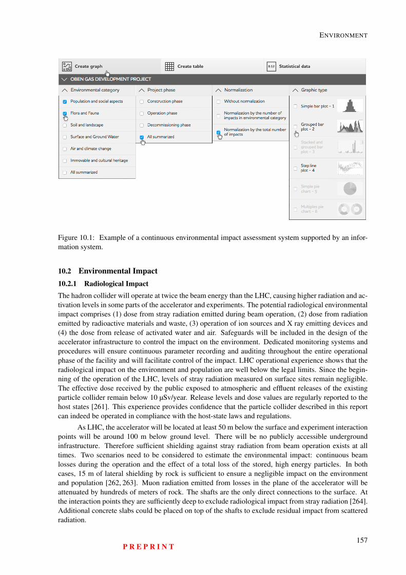
ENVIRONMENT
Envigo has features that can aid you with the analysisand visualization of the results (scores) obtained by theEIA method.
1
Figure 10.1: Example of a continuous environmental impact assessment system supported by an infor-mation system.
10.2 Environmental Impact10.2.1 Radiological ImpactThe hadron collider will operate at twice the beam energy than the LHC, causing higher radiation and ac-tivation levels in some parts of the accelerator and experiments. The potential radiological environmentalimpact comprises (1) dose from stray radiation emitted during beam operation, (2) dose from radiationemitted by radioactive materials and waste, (3) operation of ion sources and X ray emitting devices and(4) the dose from release of activated water and air. Safeguards will be included in the design of theaccelerator infrastructure to control the impact on the environment. Dedicated monitoring systems andprocedures will ensure continuous parameter recording and auditing throughout the entire operationalphase of the facility and will facilitate control of the impact. LHC operational experience shows that theradiological impact on the environment and population are well below the legal limits. Since the begin-ning of the operation of the LHC, levels of stray radiation measured on surface sites remain negligible.The effective dose received by the public exposed to atmospheric and effluent releases of the existingparticle collider remain below 10 µSv/year. Release levels and dose values are regularly reported to thehost states [261]. This experience provides confidence that the particle collider described in this reportcan indeed be operated in compliance with the host-state laws and regulations.
As LHC, the accelerator will be located at least 50 m below the surface and experiment interactionpoints will be around 100 m below ground level. There will be no publicly accessible undergroundinfrastructure. Therefore sufficient shielding against stray radiation from beam operation exists at alltimes. Two scenarios need to be considered to estimate the environmental impact: continuous beamlosses during the operation and the effect of a total loss of the stored, high energy particles. In bothcases, 15 m of lateral shielding by rock is sufficient to ensure a negligible impact on the environmentand population [262, 263]. Muon radiation emitted from losses in the plane of the accelerator will beattenuated by hundreds of meters of rock. The shafts are the only direct connections to the surface. Atthe interaction points they are sufficiently deep to exclude radiological impact from stray radiation [264].Additional concrete slabs could be placed on top of the shafts to exclude residual impact from scatteredradiation.
P R E P R I N T157
HE-LHC Conceptual Design Report (V0.11, 8 November 2018)
Activities involving handling, transport and storage of radioactive materials and the operation ofX-ray emitting equipment on the surface sites are well regulated and are no different from current oper-ations at CERN. The standard procedures in place within the current framework of radiation protectionat CERN are well developed and proven to effectively control the radiological impact.
Beam operation activates air and potentially water close to the machine. The potential environ-mental impact originating from these sources is addressed as follows:
– Air activation:Redundant, partially or fully recycling ventilation systems will limit the release of gaseous isotopes(mainly short-lived) during beam operation. This operation scheme is different from the LHC andhas the potential to help achieve annual doses to members of the public lower than those withLHC [261]. Aerosol releases are expected to be insignificant due to the low activity content andefficient air filtration at the release points, similar to the LHC. Long term experience at manyaccelerator installations confirm this estimation [261].
– Water activation:Drain water, raw water and demineralised water in the accelerator tunnel can become activatedduring beam operation and can carry trace amounts of radioactive corrosion products. Deminer-alised water circuits will be operated in a filtered, closed circuit. Leakage and infiltration water willbe collected in the tunnel and will be pumped to retention and treatment basins at the surface. Thewater will be continuously monitored so that release will only occur after clearance. Experienceshows that radioactivity in water is not a relevant source of radiological impact on the environmentat the LHC [261]. The production rate of radioactivity in water at the future collider is expectedto be lower or equal to the LHC, given the possibility to optimise pipe routing and avoid highactivation areas [262].
– Ground activation and migration of radioactivity towards the biosphere:A limited amount of rock around the tunnel will be activated. Along the arcs, the largest part ofthe collider ring, activation remains at very low levels, well within the set limits [262]. Sectionswith higher activation potentials (e.g. collimation regions, regions close to the high luminosityinteraction points) will be located in rock with negligible water migration risk so that transferto the biosphere can be avoided. Detailed ground investigations at an early design stage phasemust be carried out to optimise the tunnel placement. Considering the low levels of concentrationsproduced [262] and the small residual risk, no radiological impact is expected. Effective mitigationmeasures to limit the rock activation, such as additional wall shielding can be implemented, ifnecessary.
– Solid materials:Equipment and solid materials removed from the accelerator area can be radioactive. Their han-dling, transport, storage and elimination is subject to regulations and processes already in placefor the operating installations at CERN. No radiological exposure is expected in the environmentfrom these tasks.
The impact of ionising radiation on personnel during operation and maintenance phases, as wellas the management of radioactive waste are described in Chapter 8 Safety and Section 10.3 Waste Man-agement, respectively.
10.2.2 Conventional ImpactA preliminary review of underground and surface sites has been performed with expert organisationsin France and Switzerland [256, 265]. The studies established a working framework for the subsequentoptimisation of the placement of the particle collider which is compatible with the existing requirementsand constraints of both host states. The first investigation revealed that a placement of the collider, whichis compatible with the legal and regulatory boundary conditions in both countries can be developed. No
158P R E P R I N T
ENVIRONMENT
conflicts with geothermal boreholes, seismic activities, underground technical features such as pipelines,critical power and communication lines could be found so far. Also, no relevant conflicts with under-ground water layers or hydrocarbons could be identified and puncture of protected water reservoirs can beavoided with an optimised layout and placement. However, the current, first preliminary placement doesnot meet all requirements and constraints at the same time (technical requirements, lepton and hadroncollider optimised layout, environmental exclusion zones, socio-urbanistic constraints). Therefore, fur-ther iterations need to be done on the layout and placement optimisation in order to come to an overallcoherent proposal that meets all the criteria. In addition, dedicated underground investigations need tobe carried out soon in order to validate the preliminary findings with more accurate data and first surfacesite field studies need to be carried out in order to validate those locations, which need to be consideredfor an optimised layout and placement. The entire Geneva basin features water-saturated ground, but thewater remains locally confined. Consequently, it is unlikely that water, which is for human consumptionand which reaches the surface or rivers would be activated by ionising radiation.
Compatibility with protection of flora and fauna as well as agricultural activities has been consid-ered from the beginning by taking into account a number of national and European conservation lawsand guidelines. In this context, preliminary surface site candidates have been identified. Potential sitesfor a next iteration of the surface sites to be considered for a layout and placement iteration for a specificparticle collider scenario have been identified.
Some surface sites require further optimisation in the design phase in order to simplify potentiallandscaping or indemnity processes and to ease accessibility by road. Swiss law requires the reservationof a certain surface area for agricultural activities in order to remain self-sufficient in case of crisis [266].This constraint imposes the launch of a declassification and ground/right-of way acquisition processin the subsequent design phase. Dedicated working groups are currently being established with rep-resentatives of the Swiss confederation and the relevant offices of the Canton and State of Geneva inorder to facilitate this multi-year process. The legal framework in both countries require further detailedinformation in order to jointly develop an optimised placement. These data can only be obtained bydedicated ground investigations and need to occur before the relevant environmental impact analysis cantake place. Confirmation that inadvertent activation of water due to infiltration can be avoided may needto be verified by targeted surveys in a limited number of locations. The environmental impact duringthe construction phase, which extends over many years, needs to be studied. The reuse of the excavatedmaterial (in order of priority: on-site use, processing and reuse, landscaping, storage), construction sitetraffic, noise and dust are all elements which also need to be considered.
Official bodies of both host countries (Secrétariat Generale de la Région Auvergne-Rhône-Alpesand Département de l’aménagement, du logement et de l’énergie de la République et canton de Genève)have informed the study management that for emerging urban areas and where there is a region withhigh-value natural assets, early participation of the authorities and representatives of the population inthe further development of the project plans is required. Surface sites need to blend into the landscape.Synergies with local and regional activities that profit from the infrastructure in the host countries needto be developed. Examples include cooling via the GeniLac [267] water project, waste-heat recoveryfor residential districts and healthcare providers, possibilities for temporary energy storage and releasein cooperation with neighbouring industries. For the construction phase, particular attention needs tobe given to noise, dust and traffic. For the operation phase, topics include the consumption of water,electricity, the emission of noise and the increased need to provide all kinds of infrastructure for an evergrowing community of scientists, engineers and visitors.
The immediate subsequent design phase of the project will focus on the further optimisation of thecollider and surface site placement, based on the findings already obtained in cooperation with the hoststate authorities and their nominated technical advisory bodies for the concept phase. This work will, incompliance with the regulations of both host countries, involve representatives of the local population inorder to ensure a seamless evolution of the project design towards a later construction decision.
P R E P R I N T159
HE-LHC Conceptual Design Report (V0.11, 8 November 2018)
10.3 Waste Management10.3.1 Radioactive Waste ManagementCERN has a radioactive waste management system which has been implemented in agreement with itshost states [268]. The production, temporary storage, processing and elimination of radioactive waste isperformed according to the processes defined in the radioactive waste management system. During thetechnical design phase of the HE-LHC, the production of waste and its provisional classification will beaddressed and quantified and the temporary storage and treatment facilities required will be evaluated indetail. The choice of materials to be used in terms of their isotope production and known eliminationpathways will be optimised during the design phase.
The HE-LHC will produce similar types of radioactive waste as LHC. Given the similarity inmaterials used, the radionuclide inventory is not expected to change significantly. The expected beamloss rate per metre is comparable to the LHC. The increase in beam energy will account for an increasein activity concentration, and it is assumed that the fraction of medium level radioactive waste (classifiedin the French system as “faible et moyenne activité”, FMA, and “très faible activité”, TFA) with respectto the total volume, will not change significantly compared to LHC. The higher luminosity in HE-LHCwill lead to higher activation levels in the detectors of the high-luminosity experiments points 1 and 5,in the final focusing regions next to the interaction points, as well as in the regions with beam cleaning,collimation system and dumps. The dose rates are expected to increase compared to the levels in theLHC. In terms of handling and waste processing, technical developments will be required. These arealready planned and will be implemented for the High Luminosity LHC (HL-LHC) project.
HE-LHC will re-use the existing LHC injector chain. As an alternative, a superconducting SPScould serve as an injector. During the construction, parts of the existing accelerator chain need to beupgraded. As the components of these accelerators are already activated, the material to be removed fromthose areas will be radioactive. Both scenarios above are considered for the estimation of radioactivewaste production during the construction phase of the HE-LHC.
The full replacement of the SPS by a superconducting accelerator would generate an estimatedtotal volume of 5000 m3 (TFA) and 200 m3 (FMA) [269]. In the case of a complete decommissioning ofSPS, the temporary storage space required for the radioactive waste during the decommissioning remainsto be evaluated in terms of the disposal capacity per elimination pathway.
During the operation phase of the accelerator complex, radioactive waste will be produced fromthe collider and the injectors, mostly during the long shutdown periods. As for the LHC, about 87%of the waste generated will be TFA type and 4% FMA. The remaining 9% of the volume could beconsidered as a candidate for release from regulatory control via the clearance procedure. The averagevolume produced per year is estimated to be 2100 m3 (TFA) and 100 m3 (FMA) [269], which correspondto a considerable increase with respect to the current capacities of reception, treatment and disposal ofradioactive waste (average 400 m3 per year). The volumes given above take into account the acceleratorcomponents themselves, but not the associated infrastructure like cables and cable trays inside the tunnel.It is expected that these other elements would add less than 20 % to the total volume.
10.3.2 Conventional Waste ManagementA large-scale research facility produces conventional waste during the construction and operation phases.Typical classes of waste produced during construction are shown in Table 10.2.
While plans for the management of waste during both phases need to be established, the regulatoryframeworks of both host countries require the development of waste prevention plans for the constructionphase as part of a preparatory phase. In France, the "Plan regional de prevention et de gestion desdechets" [270] requires the project owner to include approaches that work towards a circular economy,taking into account the possibilities offered by the regional infrastructures. Waste reduction targets aredocumented in the "Loi relative à la transition énérgetique et a la croissance verte" [271]. In Switzerland,
160P R E P R I N T
ENVIRONMENT
Table 10.1: Estimates of radioactive waste for HE-LHC.
TFA FMAConstruction phaseNew SPS as injector 5000 m3 200 m3
LHC as injector 300 m3 900 m3
Operation phaseInjectors (including LHC) 650 m3/year 30 m3/yearCollider 1450 m3/year 70 m3/year
the "Ordonnance relative à l’étude d’impact sur l’environnement (OEIE)" [257] specifies the activitiesrelated to the planning of how conventional waste is managed. In the canton of Geneva, the "Plandirecteur cantonal 2030" documents the specific waste reduction targets [272].
The management of waste follows three priorities: (1) keeping the amount of conventional wasteas low as reasonably possible, (2) develop a plan to reuse the waste locally and regionally and (3) keepthe impacts of residual waste transport low.
Today, excavation material is still considered waste by law, but the legislation is evolving in manyEuropean countries. Millions of cubic metres of excavation material can be a valuable primary resource.Large-scale processes to transform and make the materials available on the market remain to be devel-oped. The FCC study has launched a research activity with the French tunnel design center (CETU), theGeneva based ”Service de géologie, sols et déchets” (GESDEC) and Montanuniversität Leoben (Aus-tria) on this subject. The study will serve as an input to the environmental impact assessment. Fur-thermore, detailed plans for the construction phase, including the identification of waste, its collection,treatment, reuse and disposal in compliance with the individual national laws have to be developed as partof the environmental impact assessment process. This plan should include measures that can be includedin procurement procedures and in the agreements concerning in-kind contributions from collaborationmembers. The procedures should address the sharing of the responsibility between project owner andsuppliers for dealing with conventional waste.
P R E P R I N T161
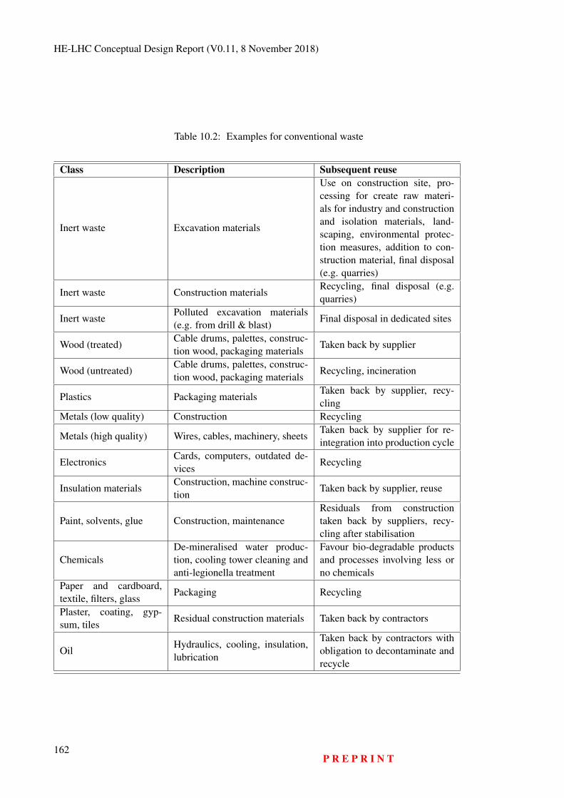
HE-LHC Conceptual Design Report (V0.11, 8 November 2018)
Table 10.2: Examples for conventional waste
Class Description Subsequent reuse
Inert waste Excavation materials
Use on construction site, pro-cessing for create raw materi-als for industry and constructionand isolation materials, land-scaping, environmental protec-tion measures, addition to con-struction material, final disposal(e.g. quarries)
Inert waste Construction materialsRecycling, final disposal (e.g.quarries)
Inert wastePolluted excavation materials(e.g. from drill & blast)
Final disposal in dedicated sites
Wood (treated)Cable drums, palettes, construc-tion wood, packaging materials
Taken back by supplier
Wood (untreated)Cable drums, palettes, construc-tion wood, packaging materials
Recycling, incineration
Plastics Packaging materialsTaken back by supplier, recy-cling
Metals (low quality) Construction Recycling
Metals (high quality) Wires, cables, machinery, sheetsTaken back by supplier for re-integration into production cycle
ElectronicsCards, computers, outdated de-vices
Recycling
Insulation materialsConstruction, machine construc-tion
Taken back by supplier, reuse
Paint, solvents, glue Construction, maintenanceResiduals from constructiontaken back by suppliers, recy-cling after stabilisation
ChemicalsDe-mineralised water produc-tion, cooling tower cleaning andanti-legionella treatment
Favour bio-degradable productsand processes involving less orno chemicals
Paper and cardboard,textile, filters, glass
Packaging Recycling
Plaster, coating, gyp-sum, tiles
Residual construction materials Taken back by contractors
OilHydraulics, cooling, insulation,lubrication
Taken back by contractors withobligation to decontaminate andrecycle
162P R E P R I N T
Chapter 11
Education, Economy and Society
11.1 Implementation with the Host States
11.1.1 Overview
Assuming 2045 for the start of operation, a decision point for a construction project in 2026 and startof construction around the end of 2028, a number of administrative processes need to be set up with thetwo host states and to be carried out during a preparatory phase. Therefore, work with the host stateauthorities has been launched in order to develop a workable schedule for the available time window.The results of this work so far show that an eight year preparatory process is required, in cooperationwith both host states and involving a diverse set of administrative processes with public engagement.A large portion of this schedule has to be completed before a decision for construction is taken. It isonly the activities concerning the preparation of the construction sites that can be postponed until after adecision to build.
The preparatory phase schedule, which has been developed jointly by CERN, representatives ofFrance and Switzerland is shown in Fig. 11.1. The plan represents a minimum-duration process that isowned and steered by the project owner (CERN an international consortium, which includes its mem-ber states and potentially, additional project partners from non-member states). Additional time may beneeded to accommodate further design iterations, in order to integrate feedback and additional require-ments by authorities and to adapt to potentially evolving regulations in the host states.
The host state authorities recommend working with locally experienced contractors for tasks thatrelate to the development of an implementation scenario in the region, to benefit from their knowledgeconcerning territorial specificities and to set up a working environment that permits putting workforceand contracts in place quickly and to be able to adjust to the evolving requirements in a timely manner.Both host states have demonstrated their will to accompany CERN throughout the preparatory phase inorder to ensure a coherent development of the project, thus increasing the likelihood of success whena decision to move forward with construction is taken by the research community. Although the legalframeworks and government structures in the two host states differ and different types of actors need tobe involved on each side of the border, the goals and scope of the individual processes are similar. Somespecific elements have to be planned and carried out in an international framework, e.g. the environmen-tal impact assessments according to the Espoo “Convention on Environmental Impact Assessment in aTransboundary Context” [260] and the establishment of an international agreement between France andSwitzerland for the purpose of preparing, implementing and operating an extension of CERN’s currentparticle accelerator infrastructure in the two territories.
163
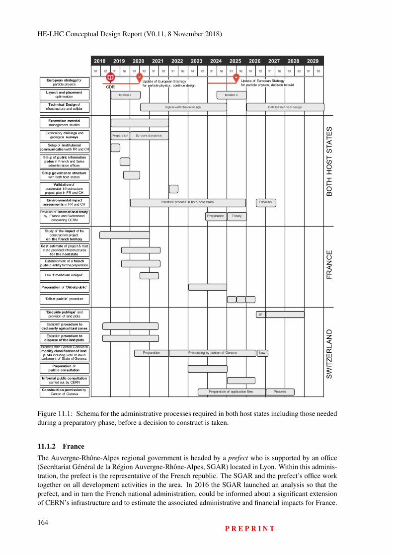
HE-LHC Conceptual Design Report (V0.11, 8 November 2018)
European strategy forparticle physics
2018 2019 2020 2021 2022 2023 2024 2025 2026 2027 2028 2029S1 S2 S1 S2 S1 S2 S1 S2 S1 S2 S1 S2 S1 S2 S1 S2 S1 S2 S1 S2 S1 S2 S1 S2
Update of European Statregyfor particle physics, continue design
Study of the impact of the construction project
on the French territory
Validation ofaccelerator infrastructureproject plan in FR and CH
Cost estimate of project & host state provided infrastructures
for the host state
Excavation materialmanagement studies
Preparation of “Débat public”
EP”Enquête publique” and
provision of land plots
Establishment of a frenchpublic entity for the preparation
“Débat public” procedure
Iterative process in both host statesEnvironmental impact assessments in FR and CH Revision
Law “Procédure unique”
Establish procedure todeclassify agricultural zones
Establish procedure todispose of the land plots
Construction permission by Canton of Geneva Preparation of application files Process
Setup of institutionalcommunicationwith FR and CH
Process with Canton Geneva to modify classification of land plots including vote of law in
parliament of State of Geneva.Processing by canton of GenevaPreparation Law
Setup governance structurewith both host states
Preparation ofpublic consultation
Informal public consultation carried out by CERN
Setup of public informationpoles in French and Swiss
administration offices
Exploratory drillings and geological surveys Surveys & analysisPreparation
Layout and placement optimisation Iteration 2 Iteration 3
Technical Design ofinfrastructure and collider High-level technical design Detailed technical design
Update of European Statregyfor particle physics, decision to buildCDR
Revision of international treatyby France and Switzerland
concerning CERNTreatyPreparation
FRAN
CE
SWIT
ZER
LAN
DBO
THH
OST
STAT
ES
Figure 11.1: Schema for the administrative processes required in both host states including those neededduring a preparatory phase, before a decision to construct is taken.
11.1.2 FranceThe Auvergne-Rhône-Alpes regional government is headed by a prefect who is supported by an office(Secrétariat Général de la Région Auvergne-Rhône-Alpes, SGAR) located in Lyon. Within this adminis-tration, the prefect is the representative of the French republic. The SGAR and the prefect’s office worktogether on all development activities in the area. In 2016 the SGAR launched an analysis so that theprefect, and in turn the French national administration, could be informed about a significant extensionof CERN’s infrastructure and to estimate the associated administrative and financial impacts for France.
164P R E P R I N T
EDUCATION, ECONOMY AND SOCIETY
This activity led to the establishment of a series of regular meetings with CERN for the development ofthe preparatory phase. France promotes a “participative democracy” [273–275], calling for a process tofind a consensus through open discussions amongst all stakeholders in the project from the conceptualstage onwards. The process starts with the development of the basic concept, a feasibility study con-cerning the infrastructural challenges, a proposal for the governance and funding and a socio-economiccost-benefit analysis. The infrastructural changes concern a wide range of topics: the use of excavationmaterial, a concept for managing conventional waste during all project phases, an energy managementplan that can be integrated with the territorial energy balance plan, plans for the consumption of resourcessuch as water, proposals for synergies with the host state to contribute to the territorial development, thedevelopment of traffic and mobility concepts and further topics. CEREMA1, a public entity associatedwith the ministry of ecologic transition and solidarity and the ministry of territorial cohesion, has pro-duced a report for the SGAR and the prefect on the impact of an FCC for the host state concerningadministrative processes and the associated financial engagements [276].
Initially, a specific project scenario needs to be produced since government offices cannot workon concrete preparatory tasks based on generic processes, but need to base their actions on so calledproject invariants that need to be considered in the update of regional development plans. This scenariodescription will cover a wide range of subjects including for instance, the purpose of the research facility,an initial proposal for the placement of the underground and surface sites, known technical infrastructurerequirements including the resources and services (e.g. electricity, water, communication, transport,emergency and security services), the high-level construction and operation project plans, a catalogueof initial risks and benefits, a list of known uncertainties, a construction and operation cost estimate, acost-benefit analysis, a first realisation plan, a governance and management structure and a preliminaryanalysis of the administrative impact on the host states. Once the scenario is validated by the office ofthe president of the republic, which is where the regional and national stakeholders come together, thepreparation of the legally required process for the public to participate in the project (“débat public”)[277] can begin. The goal of this process is to develop an acceptance and appreciation of the projectamongst the population, which forms the basis for a governmental clearance for the project owner tocontinue with the preparation. A commission defines which topics are relevant for the population andwhere there can be reasonable involvement in this process. The formal procedure lasts six months, but itrequires about two years of preparation and is concluded with a one year phase for its implementation.
After this internal preparatory phase, the project owner in close cooperation with the public de-bate commission, prepares information material (documents, databases, Web contents, booklets, videos,travelling information stands, town meetings), organises the nation-wide process, employs consultantsand companies experienced with this process, sets up the required technical infrastructure and finally,defines a schedule that will allow all relevant public representatives to be involved. This takes about oneyear. According to the law revised in 2017 [278], the three-year period also involves the publication ofsummaries of the environmental impact assessment. At the end of the formal “débat public” phase, afollow up consultation process, which continues until the end of the construction phase, must be put inplace. Its findings need to be integrated in an iteration of the technical design and the project documents.
Once the national committee of the public enquiry (CNDP) [277] agrees that the documentationis mature, the formal open discussion can be launched. This milestone is associated with a certainrisk, since if the process is insufficiently mature an extension of the preparatory period will be required.During this consultation phase, the plan for the project is presented and discussed with representatives ofthe population at local, regional and national levels during formal, recorded and audited sessions [279].The project owner is asked to collect all questions and provide answers in a secure and auditable way.The findings lead to another iteration of the required project documentation (e.g. environmental impactassessment, plan for the management of excavation material and waste, energy management plan, trafficand mobility concept, land and rights of way acquisition plan, final land plot valuation). After the
1http://www.cerema.fr
P R E P R I N T165
HE-LHC Conceptual Design Report (V0.11, 8 November 2018)
successful completion of this phase, the acquisition of rights of way of underground volumes and surfaceplots can start.
A public enquiry (“Enquête publique”) concludes the process by confirming the agreed infras-tructure design which emerged from the public debate phase. If the tribunal has no objections, theFrench government will issue the approval of the infrastructure project’s utility for the nation (”Déclara-tion d’utilité publique”) [280] and the project owner can proceed with the preparation of a constructionproject. The acquisition of the rights of way and land plots can take place concurrently with the civilengineering calls for tender.
It is important to note that the entire process relies on the parliamentary submission and acceptanceof a law that needs to be prepared for defining a unique process for the environmental authorisation [281]of a new research infrastructure project. Such a law includes a list of national laws and regulations thatapply to the project, adjustments of existing laws, indications of which laws do not apply and specificregulations concerning particularly relevant topics such as the management of excavation material. Thisinstrument, which appeared in 2016, specifically targets the timely preparation of large-scale projects ofpublic interest such as the Grand-Paris [282] project.
11.1.3 Switzerland
Switzerland is a republic, federating significantly autonomous “Cantons”; this system of semi-directdemocracy which has been in place since 1848, is unique. The country has a long standing tradition ofinvolving the population at all levels (municipal, cantonal and federal) and at all phases of infrastructureprojects. The procedures differ substantially in the different Cantons. Therefore, a workable process hasbeen developed with the assistance of the Canton and State of Geneva, the Swiss permanent mission forinternational organisations in Geneva, the representatives of the Swiss Confederation and a consultantfor public construction project administrative procedures.
Although CERN’s primary communication partner for administrative matters in Switzerland isthe permanent mission and the ministry of foreign affairs, the common work so far revealed that for thepreparatory phase of a large scale particle collider project located in the Canton of Geneva the majorityof processes will be carried out together with the State Office of Geneva. The federal government willbe involved in the entire process with respect to the approval of applicable federal laws, regulationsand financial contributions. In 2017, the “Structure de Concertation Permanente” (SCP) was establishedfor this purpose. It includes Swiss government representatives at federal and cantonal level, expertsfrom different administrative domains on an "as-needed-basis" and representatives of CERN for variousdevelopment areas, including future projects.
The schedule, which has been developed in the frame of the SCP takes note of the status of CERNas an international organisation developing research instruments on a global-scale, which are techni-cally and organisationally unique. Several years before initiating the cantonal formal processes to obtainpermission to construct, the acquisition of rights of way on land plots and the declassification of thoseagricultural zones needed for construction have to be launched and successfully completed. The author-ities assume that CERN also carries out a set of informal processes which include a public consultationprocess, which is similar to the French “débat public”, with a preparatory period to create public infor-mation booths, information materials and events, public hearings, the establishment of an office to collectquestions and to develop responses. In addition, the engagement of a diverse set of stakeholder groupsat municipal, cantonal and federal levels is required, with an initial institutional communication strategyand plan which will be developed in close cooperation with the cantonal and federal authorities.
In order to be able to meet the envisaged overall schedule, which aims to start construction towardsthe end of 2028, two major preparatory actions have been identified by the representatives of the SwissFederation and the Canton of Geneva that need to be initiated as soon as possible: a working group needsto develop a procedure in cooperation with the representatives of the Swiss Federation and the Canton of
166P R E P R I N T
EDUCATION, ECONOMY AND SOCIETY
Geneva that permits CERN to request the Canton of Geneva to process the re-classification of agricultur-ally reserved, green-belt zones (“Surface d’assolement”) [283, 284]. The working group needs to tacklethe process based on concrete, yet preliminary and non-binding assumptions of surface sites in order todevelop concrete plans for the de-classification process, which will include mitigation and compensationmeasures. This process goes along with the development of a re-classification plan for a concrete set ofpotential plots of land that need to be acquired or rented long-term, for the construction project at a laterstage. At the same time, another working group needs to develop the procedures to obtain the rights ofway or the acquisition of those specific plots of land on behalf of CERN. The procedures are expected todiffer for the different specific plots and involve the development of negotiation and acquisition strategiesand the drawing up of plans to provide the sites to the international organisation. Some areas may beprovided only for limited periods of time, for instance during the construction and commissioning peri-ods. Expropriation of land in the interest of the public is generally avoided in Switzerland and thereforenegotiation with the owners of potential surface sites must be started early in the preparatory phase, toallow sufficient time to adjust the placement if needed. This work goes along with an evaluation of themarket value of the land plots, notification of the cantonal authorities of the intent to use the plots foran infrastructure project and pre-agreements with land owners for obtaining the rights of way. Theseprocesses have to be managed by CERN or a CERN mandated project consultant and rely on the activeparticipation of a number of federal and cantonal offices.
Although an environmental impact assessment is formally only required for the creation of parkingspaces for more than 500 cars and for the processing of excavation materials of more than 10,000 t peryear on a site [257], it is seen as good practice and in agreement with the Espoo Convention that theproject owner pro-actively carries out this process. A specific framework needs to be developed to beable to perform one single integrated environmental impact assessment of the project across the two hoststates with the possibility to provide information in a way that is accepted by the relevant administrationoffices in the two nations.
Referenda and federal approval processes may be applicable. They need to be identified duringthe preparatory phase as soon as specific topics are identified by the authorities that may require publicapproval. In such cases, dates need to be agreed with the federal and cantonal authorities to limit publicinitiatives to a certain period so that appropriate reaction to enquiries from citizens and interest groupscan be made without jeopardizing the overall project schedule.
In order to get started with a number of different federal and cantonal offices efficiently, CERN isasked to initially put emphasis on the establishment of an institutional communication plan and its imple-mentation. This will inform all officials who have to support the work of CERN about the project scope,goals, scale and schedule. Regular informal meetings with the regional population, their representativesand various interest groups are welcomed from the initial design phase, since transparency is consideredthe most efficient aspect of activities for the preparation a potential project.
Authorisation for construction can be requested after successful completion of the necessary stepsand before a decision to build takes place. In the same way as is requested by the French authorities, aCost-Benefit-Analysis (CBA) has to be delivered. The Swiss authorities encourage the idea of aimingat creating added value from training, tourist development, creation of a technology pole and synergiesconcerning transport and energy recovery in the Geneva region.
11.2 Socio-Economic Opportunities11.2.1 Introduction and Motivation
Cost Benefit Analysis (CBA) [285] for conventional infrastructures such as roads, power plants, energydistribution networks and public transport systems is a useful tool to identify, quantify and communicatethe potential value, in addition to the gain of scientific knowledge, that a new research facility can bringto society.
P R E P R I N T167
HE-LHC Conceptual Design Report (V0.11, 8 November 2018)
A preliminary, quantitative study of the LHC/HL-LHC project using this method has been carriedout [224] to establish the foundation of an impact analysis of a future collider. The study has beenperformed by three independent organisations: University of Milan, University Roma Tre and the Centrefor Industrial Studies (CSIL), Italy. The result reveals that the estimated Net Present Value (NPV) for theentire, combined LHC/HL-LHC programme over a period of 45 years is positive, taking into account anannual social discounting rate of 3 %. The likelihood of generating benefits of up to 5 billion CHF overthe life of the programme is 80 % [?]. This shows that a research facility like the FCC can generate addedvalue for both industry and society. Despite the significant investment, the overall costs are dominatedby operational expenditure.
CBA has become a requirement for the preparatory phase of research facilities. The upcoming ES-FRI roadmap includes a specific request [286] for it and the EC staff working document on sustainabilityof research facilities asks for it. In 2018 an EC supported H2020 project, RI Impact Pathways [287],was launched with CERN’s participation to develop a uniform CBA method for research facilities inthe European Research Era (ERA). Here, the results from the study on the combined LHC/HL-LHCprogramme are presented. This work serves as a foundation for a dedicated cost benefit analysis of oneparticular collider scenario that needs to be carried out at an early stage of the preparatory phase. Theresults of the investigations so far triggered a set of complementary surveys and studies by the universityof Milan in cooperation with CSIL in order to establish a set of solid input parameters and assumptionsfor a CBA of a post-LHC particle collider scenario.
So far, the studies of the LHC/HL-LHC programme revealed six economically relevant bene-fits: (1) the value of scientific publications, (2) technological spillover, (3) training and education, (4)cultural effects, (5) services for industries and consumers and (6) the value of knowledge as a publicasset. There are two direct socio-economic benefits that stem from the dissemination of scientific in-formation [288–290] (publications, reports, conference presentations): first, the direct value of scientificproducts is conservatively estimated to be equivalent to their production costs [291, 292]. Second, thevalue of publications produced by an additional tier of scientists which cite the scientific products di-rectly emerging from the research infrastructure is equivalent to the cost of their production. For theLHC/HL-LHC project, this added value is around 2% of the total benefits [289]. This report focusses onthe findings concerning training, impact on industry and cultural effects in the following sections.
11.2.2 The Value of TrainingThe value of education and training is the single largest socio-economic benefit of a large-scale, hi-techresearch facility. The impact is high if it is carried out in an open, international environment with strongcooperation between educational institutes, research centres and industrial partners (the “knowledge tri-angle”) [293]. A conservative estimate of the net present value added to the lifetime salary of early stageresearchers (master’s degree, doctoral degree and post-doctoral researcher) after leaving the LHC/HL-LHC project has been estimated. The lifetime salary premium for people who perform research anddevelopment in the scope of the LHC/HL-LHC project at CERN ranges between 5% and 13% in excessof the salary premium of the acquired academic degree. This translates into an absolute lifetime salarypremium of about 90000 Euro to 230000 Euro per person with an average added value of ca. 160000Euro for a doctorate degree obtained during a research period at CERN (2018 currency value) [294,295].Based on CERN’s current training programme capacity, during a 15 year construction phase and an ini-tial operational phase of 20 years. 40,000 individuals would generate more than 6 billion Euros for theeconomies of the participating nations. The training value potential depends significantly on the possibil-ity to acquire inter sectoral and transferrable skills [296] and the number of supervisors that are availableto ensure the quality of the training provided.
These results triggered a process with the two host-states [297] to find how the value of trainingcan be further increased. Proposals include extending the training to non-academic domains (appren-tices, technical schools), continuous professional training (partnerships with companies in the frame of
168P R E P R I N T
EDUCATION, ECONOMY AND SOCIETY
maintenance and upgrades as well as the increasing exploitation of under-used equipment), partnershipswith public services (healthcare providers, public security and emergency services) and the continued en-largement of the training opportunities for non-technical domains (e.g. management, finance, economy,law, business administration). Also, joint academic education through partnerships with universities andindustry should be further strengthened. The EASITrain H2020 Marie Skłodovska Curie Action Innova-tive Training Network project [298], launched by 11 institutes collaborating in the FCC and 13 industrypartners is a first step in this direction and it includes a goal of developing a European joint doctorate inapplied superconductivity.
11.2.3 Opportunities for Industries and Technological SpilloverThe industrial activities that emerge from physics research projects are important for the European econ-omy [299]. A key figure on which all estimates of industrial impacts are based is the utility factor.It indicates that every Swiss franc spent on co-development and customisation projects with industrialpartners generates, on average, 3 Swiss francs worth of follow-up sales revenues for the industrial part-ner [300]. The LHC/HL-LHC CBA study provides quantitative evidence that companies participating inthe project and exhibiting medium to high levels of innovation also benefit from a measurable increase oftheir earnings before interest and taxes [301, 302]. The relevance of this effect has been tested using theaccounting figures of 669 companies involved in CERN procurements worth more than 10,000 CHF anda control group [303]. The majority of companies report that the main benefit stems from the learningexperience in such a project [?].
The LHC/HL-LHC CBA also reveals that there is added economic value due to improved products,services and operation models of∼10 billion CHF: more than 40 % of the total cost (capital and operationexpenditures). Further intensification of industrial involvement in core R&D activities in the frameworkof a well-planned industrialisation strategy can increase this share, so that a payback of 50 % of the totalcosts can become realistic. The most prominent example for such research-induced industrialisationis the development of Nb-Ti superconducting wires for the Tevatron collider which triggered the massproduction of medical magnetic resonance imaging (MRI) devices [304]. Another noteworthy example isthe development of large-scale cryogenic refrigeration plants – the architecture and machinery developedfor helium liquefaction for use in particle accelerators has been the industry standard for almost 40years [305].
For a future particle collider, the benefits emerging from procurement and co-innovation dependon (a) the investment volume, (b) the potential for innovation related to the individual subsystems and (c)on the value of the utility factor. It is not yet possible to reliably quantify the overall impact for industry.A dedicated study for a specific accelerator scenario needs to be carried out, once the detailed technicaldesign starts. Technologies that lead to innovation on a broader scale (see Fig. 11.2) for the variousparticle collider scenarios (FCC-ee and FCC-hh) include superconducting radiofrequency systems for alepton collider (estimated benefit for industries about 150 MCHF), superconducting wires for a hadroncollider (estimated benefit for industries around 1200 MCHF depending on the revenue margin that thesupplier is able to generate for non-research customers), construction and testing of superconductingmagnets for a hadron collider (estimated benefit for industries from 150 to 200 MCHF, depending onthe potentials of the different technologies along the magnet manufacturing value chain) and large-scalecryogenic refrigeration infrastructure for a hadron collider (estimated benefit for industries from 250 to300 MCHF).
An earlier study [306] has shown that hi-tech companies can transfer the knowledge and experi-ence acquired during work with CERN to new products and services easier than companies who offeroff-the-shelf products and services. Therefore, it is crucial to make an effort to cooperate with industryon increasing the potentials for other fields, such as civil engineering. As Figure 11.3 shows, the potentialindustrial spillover for a 100 km civil engineering project with tunnel and caverns is quite different, if theproject is carried out purely as contractor work or if co-innovation is introduced for advanced excavation
P R E P R I N T169
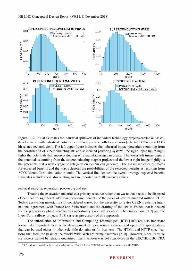
HE-LHC Conceptual Design Report (V0.11, 8 November 2018)
Figure 11.2: Initial estimates for industrial spillovers of individual technology projects carried out as co-developments with industrial partners for different particle collider scenarios (selected FCC-ee and FCC-hh related technologies). The left upper figure indicates the industrial impact potentials stemming fromthe construction of superconducting RF and associated powering systems, the right upper figure high-lights the potentials that superconducting wire manufacturing can create. The lower left image depictsthe potentials stemming from the superconducting magnet project and the lower right image highlightsthe potentials that a new cryogenic refrigeration system can generate. The x-axis indicates estimatesfor expected benefits and the y-axis denotes the probabilities of the expected benefits as resulting from25000 Monte Carlo simulation rounds. The vertical line denotes the overall average expected benefit.Estimates include social discounting and are reported in 2018 currency values.
material analysis, separation, processing and use.
Treating the excavation material as a primary resource rather than waste that needs to be disposedof can lead to significant additional economic benefits of the order of several hundred million CHF2.Today, excavation material is still considered waste, but the necessity to revise CERN’s existing inter-national agreement with France and Switzerland and the drafting of the law in France that is neededfor the preparatory phase, renders this opportunity a realistic scenario. The Grand-Paris [307] and theLyon-Turin railway projects [308] serve as pre-cursors of this approach.
The introduction of Information and Computing Technologies (ICT) [309] are also importantlevers. An important facet is the development of open source software and open ICT specificationsthat can be used either in other scientific domains or for business. The HTML and HTTP specifica-tions that form the basis of the World Wide Web are prime examples [310]. However, since its valuefor society cannot be reliably quantified, this invention was not considered in the LHC/HL-LHC CBA
28.5 million tons of molasse at a value of ca. 35 CHF/t and 260000 tons of limestone at ca. 85 CHF/t
170P R E P R I N T
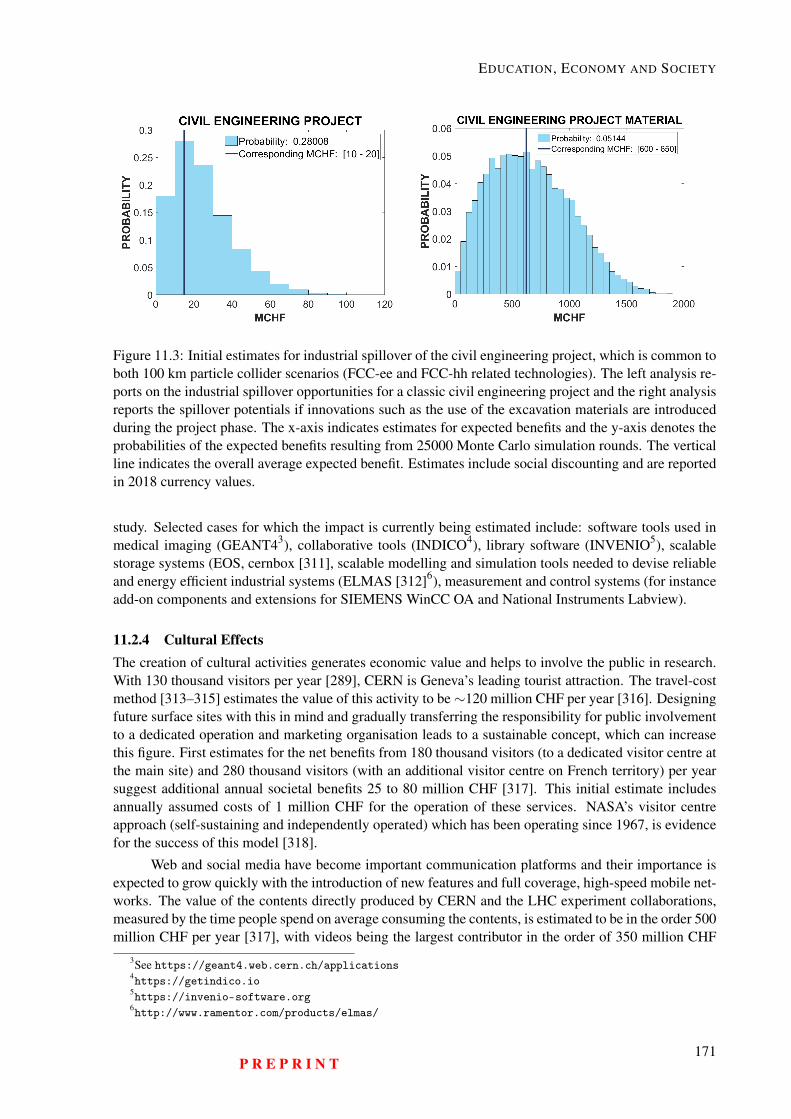
EDUCATION, ECONOMY AND SOCIETY
Figure 11.3: Initial estimates for industrial spillover of the civil engineering project, which is common toboth 100 km particle collider scenarios (FCC-ee and FCC-hh related technologies). The left analysis re-ports on the industrial spillover opportunities for a classic civil engineering project and the right analysisreports the spillover potentials if innovations such as the use of the excavation materials are introducedduring the project phase. The x-axis indicates estimates for expected benefits and the y-axis denotes theprobabilities of the expected benefits resulting from 25000 Monte Carlo simulation rounds. The verticalline indicates the overall average expected benefit. Estimates include social discounting and are reportedin 2018 currency values.
study. Selected cases for which the impact is currently being estimated include: software tools used inmedical imaging (GEANT43), collaborative tools (INDICO4), library software (INVENIO5), scalablestorage systems (EOS, cernbox [311], scalable modelling and simulation tools needed to devise reliableand energy efficient industrial systems (ELMAS [312]6), measurement and control systems (for instanceadd-on components and extensions for SIEMENS WinCC OA and National Instruments Labview).
11.2.4 Cultural EffectsThe creation of cultural activities generates economic value and helps to involve the public in research.With 130 thousand visitors per year [289], CERN is Geneva’s leading tourist attraction. The travel-costmethod [313–315] estimates the value of this activity to be∼120 million CHF per year [316]. Designingfuture surface sites with this in mind and gradually transferring the responsibility for public involvementto a dedicated operation and marketing organisation leads to a sustainable concept, which can increasethis figure. First estimates for the net benefits from 180 thousand visitors (to a dedicated visitor centre atthe main site) and 280 thousand visitors (with an additional visitor centre on French territory) per yearsuggest additional annual societal benefits 25 to 80 million CHF [317]. This initial estimate includesannually assumed costs of 1 million CHF for the operation of these services. NASA’s visitor centreapproach (self-sustaining and independently operated) which has been operating since 1967, is evidencefor the success of this model [318].
Web and social media have become important communication platforms and their importance isexpected to grow quickly with the introduction of new features and full coverage, high-speed mobile net-works. The value of the contents directly produced by CERN and the LHC experiment collaborations,measured by the time people spend on average consuming the contents, is estimated to be in the order 500million CHF per year [317], with videos being the largest contributor in the order of 350 million CHF
3See https://geant4.web.cern.ch/applications4https://getindico.io5https://invenio-software.org6http://www.ramentor.com/products/elmas/
P R E P R I N T171
HE-LHC Conceptual Design Report (V0.11, 8 November 2018)
per year. Channels combining different types of media have the highest impact (text interleaved withshort videos, interactive info-graphics, apps, functions that encourage the reader to provide interactivefeedback and to participate in collective tasks to shape opinion and to create new contents). The doc-umented impact suggests that investing further in the provision of complementary, media-rich contentspermits multiplying today’s measured impacts many times. If technology evolutions such as augmentedreality, tailored contents for different audiences, multi-language support, high-resolution virtual realityare adopted quickly, the research facility can significantly leverage the cultural effects.
In all cases, the research infrastructure operator needs to ensure that the content is made availableby independent Web and social media content producers via a communication network that works well.Other powerful cultural products are computer programs (apps) which engage their users in the research.Higgs Hunters [319] is a good example of such a citizen science project – it attracted 32000 volunteersin one year. The strong use of this technology by other research communities [320] motivates the de-velopment of further cases in the particle accelerator and high-energy physics domain. Computationalphysics applications as needed for the lepton collider FCC-ee and data analysis challenges as created bythe hadron collider FCC-hh are ideal topics to create citizen science and public engagement programmesthat also help disseminating the concepts of modern physics (“the Standard Model of Particle Physics”),which have so far not reached a wide audience.
Exhibitions such as Extreme [321] in Italy and Begin [322] in Austria, combined with interactivesessions and public events are an effective way to introduce the public to the research carried out intheir countries in their own language. Their value so far measured by the number of visitors and thetime visitors dedicate has been estimated to be in the order of 4.4 million CHF per year. The mostsuccessful item is the travelling LHC interactive tunnel, which alone creates about 1.1 million CHF ofsocietal benefit per year, because it engages a large number of people for substantial amounts of time.When designed and created in cooperation with experienced museums and science exhibition centres inthe member states and when accompanied by Web and social media contents that helps to amplify theimpact, the concept is a powerful vehicle to create a lasting awareness and promote the vision of a futureparticle-collider facility.
The value of numerous books, TV shows, films and music produced by people not directly par-ticipating in the research programme undoubtedly has a further economic impact. It is a challenge toprovide evidence for a causal relationship between a particular communication product and the researchfacility’s activity. Therefore it is difficult to quantify the impact and the study is ongoing, focussing onvideo productions, TV and journal coverage and books.
CERN builds an image amongst the population of all member states through its communicationactivities. Because it exists and deals with questions that touch everybody CERN has a value for every-body. This value has been estimated with ‘Willingness To Pay’ (WTP) [285] surveys in CERN’s memberstates specifically targeting the topic of a future particle collider. An initial LHC/HL-LHC CBA studysuggested a total discounted value of 3.1 billion CHF for the total project period from 1993 to 2038. It isbased on the assumption that the average annual voluntary contribution per year and person is 1.5 Euro.For the LHC/HL-LHC programme this very conservative, lower-bound discounted estimate representsabout∼12 % of the total forecast impact [224]. However, a recent survey among French taxpayers [323]performed to establish solid assumptions for a CBA of a post-LHC particle collider infrastructure sug-gests a much higher WTP of around 4.7 CHF per taxpayer and year. In comparison, French taxpayerscontribute to space research through funding of CNES with 35 Euro per year [324]. In addition a highernumber of eligible contributors in CERN member states of the order of 350 million people, needs to beconsidered for future WTP estimates.
11.2.5 Impact PotentialAn initial set of recommendations to increase the impact of a post-LHC particle collider beyond thescience community was developed in the frame of the CBA work carried out during the FCC study. It in-
172P R E P R I N T
EDUCATION, ECONOMY AND SOCIETY
volved the University of Milano, the Centre for Industrial Studies and the University Roma 3 in Italy, thefield study carried out by the company “iddest”, which specialises in public consultation processes [325]and finally the common working groups with French [297] and Swiss [326] host-state representatives.
Table 11.1: Opportunities to further strengthen the reuse of a large-scale particle collider infrastructure
Domain Actions
Training
Common inter-sectoral education programmes with universities worldwide, exten-sion of trainee programmes with industry, extension of adult training in the scope ofdevelopment and service contracts, strengthening of the involvement of non-STEMdomains in the training programmes. Reliable reporting of the research infrastructureinduced salary premium will require periodic surveys via the CERN Alumni network,HR offices of collaborating universities and research centres as well as cooperationwith national and international statistics institutes and selected industrial partners.
Industry
Technological competence leveraging projects to increase the probability of creatingproducts and services from leading-edge technologies developed in the framework ofthe new particle accelerator, strengthening of the participation in the developmentof standards and specifications, develop technological spillovers for conventionalproject domains such as civil engineering, increase the focus on the developmentof information technologies, open specifications and open source software with usecases outside the particle accelerator and high-energy physics domain, closer workwith national ministries of economy and industry interest groups to create densernetworks with industrial partners.
Culturalgoods
The channels with the highest impact potential are social media and on-line contents.It makes sense to further strengthen the presence in this domain, to complement itwith media-rich contents (videos, interactive applications, augmented reality, citizenengagement). Creation and operation of high-quality and high-capacity visitor cen-tres by an independent profit-making organisation that continuously involves the sci-entists, citizen science projects in collaboration with academic partners worldwide,promoting exhibitions developed by professional organisations in the member states,particular projects in other areas of the world (Africa, Asia, South America).
All consultants for relations with the public recommended the creation of a future collider am-bassador programme. A dedicated communication plan, regular training and support material for targetgroups at different levels (institutional, local, regional, national, international) should make project mem-bers at all levels and from all sectors effective advocates of a future project. In the member states, thissource of information will be the first and most effective communication channel to promote future re-search, to explain its benefits and challenges and to explain its purpose in simple terms. It is importantthat this programme also addresses common concerns. It should include a balanced set of ambassadorswith different professional, cultural and personal backgrounds. The narratives should focus on whatstimulates people’s imagination like the origin of the universe, the nature of the matter which we aremade of and where we come from.
P R E P R I N T173

HE-LHC Conceptual Design Report (V0.11, 8 November 2018)
174P R E P R I N T
Chapter 12
Strategic Research and Development
12.1 IntroductionThe information presented in this volume presents a feasible concept for a future circular collider. Thelevel of detail corresponds to the conceptual development stage requirements as defined in the EuropeanStrategy for Research Infrastructures (ESFRI) methodology roadmap [327, 328]. At this level, a numberof concepts are presented that can be screened by experts in the domain, funding agencies and otherstakeholders. It forms the basis for an implementation project of one of the scenarios and prepares theground for developing a funding concept. The subsequent preparatory phase focuses on the developmentof the implementation plans and therefore relies on coming to credible designs based on a set of technolo-gies that enable the research infrastructure to be built. At this stage, any project of such scale, ambitionand with a long-term vision spanning many decades comprises a number of uncertainties with differentprobabilities and potential impact. Appendix C in the appendix compiles the most relevant uncertaintiesfor the specific collider scenario presented in this volume. Before a decision to build is taken the most rel-evant technical uncertainties require investments in research and development to bring the technologiesto readiness levels that permit the construction and subsequent operation with acceptable project risks.Therefore, the immediate next step, the design phase, focuses on the development of a technically achiev-able and coherent blueprint, which successfully responds to the requirements and concepts presented atthis first stage. The R&D topics presented in this section are considered ”strategic”, since they representthose key elements which are considered necessary prerequisites to come to a technical design that canactually be implemented within acceptable time and cost envelopes. The topics are not ranked in anyway and many more research topics need to be addressed before arriving at a particle collider technicaldesign which can meet the physics goals and which can be operated in a sustainable fashion throughoutthe planned operational period. However, additional topics which are not considered decisive in termsof technical feasibility or operational sustainability are not presented in this volume. This allows thescenario to be screened whilst remaining focused on the physics opportunities, the long-term importancefor the worldwide particle and high energy physics community and on the most essential technical feasi-bility questions. It is assumed that also the existing diverse and vibrant set of R&D activities in the fieldof particle accelerator technology will continue and will lead to a converging programme for a futureparticle collider, nourished by cross-fertilisation of different particle acceleration technologies, designstudies and the continuous optimisation of facilities in operation. Some of the enabling technologies areequally important for all three particle collider scenarios (FCC-hh, FCC-ee and HE-LHC).
– 16 Tesla superconducting high-field, dual aperture accelerator magnet– Cost-effective and high-performance Nb3Sn superconducting wire at industrial scale– Energy efficient, large-scale cryogenic refrigeration plants for temperatures down to 40 K
175
HE-LHC Conceptual Design Report (V0.11, 8 November 2018)
– Invar based cryogenic distribution line– Superconducting septum magnet– High-speed, high-power switching system for beam transfer elements– Efficient radiofrequency power sources– Decentralised, high-capacity energy storage and release– Particle detector technologies– High-power solid state amplifiers– Efficient and cost-effective DC power distribution
12.2 16 Tesla Superconducting MagnetMotivation
At the design stage of the LHC, the dipole field level was chosen to give the highest collision energypossible with Nb-Ti technology, cooling the magnets to 1.9 K and operating them with a 14 % marginon the load line.
For the future hadron collider a similar approach is used. The goal is to fill the 100 km longtunnel with magnets that can provide the highest field using the technology which provides the bestcost/performance ratio. With Nb3Sn technology, hadron beams of 50 TeV can be achieved in a 100 kmlong circular accelerator with bending magnets with a nominal field of 16 T. This is about twice the 8.3 Tgenerated by the Nb-Ti magnets in the LHC and about 5 T higher than the 11 T of the Nb3Sn-baseddipole magnet of the high-luminosity LHC (HL-LHC). The cost of such superconducting magnets isdominated by the amount of conductor and increases rapidly when the parameters are approaching theconductor critical surface. Therefore, it is important to operate with the smallest possible margin on theload line to exploit the full potential of the conductor.
Objectives
The goal is to develop a viable design for a superconducting 16 T, dual-aperture magnet. The designneeds to be verified using simulations first and then with short (∼1.5 m) models. Eventually, full-scalemodels need to be built to validate the design. This programme depends on a separate R&D programmefor the development of a high-performance, cost-effective Nb3Sn superconducting wire. It is assumedthe FCC-hh will work with the same 14 % margin on the load line as was adopted for the LHC. TheR&D programme aims to achieve the margin, which is lower than today’s state-of-the-art Nb3Sn HL-LHC magnets, where the margin ranges between 20 and 22 %. A main concern for the programme isto achieve reliable operation with a margin of 14 % or even as little as 10 %. It is also necessary toreduce the superconducting magnet training so that initial test times are shorter and consequently fewerresources are needed and finally, reliable operation during the nominal thermal cycle must be established.
Description of the work
The programme spans three distinct domains:
1. The development of various magnets including the development of the associated design and man-ufacturing technologies.
2. The design, construction and verification of magnets for R&D purposes.3. The design, construction and validation of model magnets.
The design studies aim to develop feasible concepts for a high-field accelerator magnet. Thedesigns are verified and compared using electromechanical performance simulations including their be-haviour under mechanical stress. The design process includes the identification and specification of new
176P R E P R I N T
STRATEGIC RESEARCH AND DEVELOPMENT
structural components for the ferromagnetic yoke and the coil end spacers and wedges. It also includesthe development and specification of new resin impregnation systems and the development of advancedinternal splicing techniques for the superconducting cables. The design process will also lead to thedevelopment of an in-depth understanding of the mechanical conductor and coil stack properties cor-responding to the various manufacturing processes (insulation materials and layout, heat treatment andimpregnation).
The construction of magnets for R&D purposes is based on the study of short model coil (SMC),enhanced racetrack model coil (ERMC) and racetrack model magnet (RMM) assemblies. The SMC isused as an intermediate stage to determine the effectiveness of the technologies developed for trainingimprovements, conductor insulation and impregnation resins, as well as specific production steps, inparticular the adhesion conditions between coil and poles. ERMCs are developed in two variants withnon-graded and with graded coils. They facilitate the assessment of strategies for coil manufacture andassembly, namely the interface between conductor and end spacers or conductor and pole, heat treatmentand impregnation conditions (volume, stress), internal splices for the graded versions, loading condi-tions to minimise degradation and training and finally, the management of transitions (layer jump, ends).Eventually, ERMCs will demonstrate that the field level of 16 T can be achieved with some margin andwith limited or no training. The RMM and the ERMC share the same structure but the insertion of an ad-ditional coil between the two pancakes of the ERMC creates an aperture of 50 mm over a straight sectionof 470 mm in addition to a 250 mm layer jump. The structure will be designed to contain large longitudi-nal rods made of stainless steel or aluminium, tightened in different ways to explore various conditions oflongitudinal loading, including extreme situations of nearly rigid boundaries. These magnets will enablethe training performance for a straight section of a real accelerator magnet to be determined. In addition,the measurement of the magnetic field in the aperture will be possible, even in the absence of free accessfrom the ends. Finally, the magnetisation effects over the powering cycle, including reproducibility fromcycle to cycle as a function of the injection field will be recorded.
By building short models of all the viable options explored by the EuroCirCol H2020 EU projectthe cosine-theta, block coils, common coils and canted cosine-theta designs can be verified under realisticconditions. Eventually, full-scale models of the most promising designs have to be constructed to validatethe approach before a decision to launch a construction project for a high-energy hadron collider can betaken.
Collaboration with universities and research institutes
From the beginning this R&D programme has been a collaborative endeavour that requires the com-mitted involvement of universities and research centres from around the world. The EuroCirCol H2020study initiated a worldwide consortium to develop and explore designs of different high-field acceleratormagnets. Research institutes with established track records in the design and development of super-conducting high-field magnets need to intensify their contributions further. Model magnets are alreadyplanned to be constructed by CERN (international organisation), CEA (France), CIEMAT (Spain), INFN(Italy), PSI (Switzerland) and Fermilab (USA). The design, construction and testing activities include thecooperation of well-known institutes and universities such as EPFL (Switzerland), KEK (Japan), Techni-cal University of Tampere (Finland), Karlsruhe Institute of Technology (Germany), University of Patras(Greece), University of Twente (The Netherlands), University of Geneva (Switzerland), National HighMagnetic Field Laboratory (USA), Brookhaven National Laboratory (USA) and Berkeley Lab (USA). Inparticular, the high-field magnet development programme led by the Department of Energy (USA) willbe a crucial factor on the way to determine a viable design for a 16 T magnet. In the near future, the con-sortium needs to be enlarged with additional academic partners, in particular universities and institutesin Russia with a track record in the development of high-field superconducting magnets. The consortiumalso needs the involvement of academic partners in Asia and more regional partners in North America,including Canada.
P R E P R I N T177
HE-LHC Conceptual Design Report (V0.11, 8 November 2018)
Collaboration with industrial partners
The design and development of the 16 T magnet relies strongly on the capability to manufacture, installand operate a large number of devices. Therefore, industrial partners will be included at all stages of theR&D programme, from the development of fundamental technologies through assembly and process-related activities to quality management, installation, maintenance and repair concepts. Co-developmentwith industrial partners during the R&D phase prioritises the following key topics: automated windingsystems with integrated quality control, quality improvements and resource optimisation of impregnationand heat treatment, the optimisation of assembly, the optimisation of internal and external interfacesto improve assembly, testing, installation, maintenance and repair. These activities will include thedefinition of collaborative, EC co-funded, projects to increase the impact of transferring technologicaldevelopments from research to industry.
Milestones and deliverables
Table 12.1: Milestones and deliverables for 16 T magnets
Title and description Year4 different electro-mechanical magnet designs studied 2019SMC tested 2019ERMC tested 201915 T cos-theta model (US) tested 2020RMM tested 2021SMC, ERMC, RMM results 20223 short 16 T models validated 20231 long 16 T model validated 2025
12.3 Nb3Sn WireMotivation
The feasibility of a 16 T superconducting accelerator magnet with two apertures of 50 mm each dependson the availability of an affordable conductor tha can deliver a current density (Jc) of at least 1500 A/mm2
at 4.2 K and 16 Tesla [329]. If a high-energy hadron collider was to be built as an immediate next stepafter the LHC/HL-LHC programme, Nb3Sn is seen today as the only superconducting material that canbe produced at the rate and in the quantity needed for a series production of thousands of magnets by2030 [330]. This material is being produced for use in the magnets of the HL-LHC upgrade project,the first application of Nb3Sn technology in a particle accelerator. Industrial production of such wire ispresently with one leading company in the field (Bruker) that masters two processes: internal tin (RRP©)and powder-in-tube (PIT). A performance up to 1200 A/mm2 at 4.2 K in a field of 16 T is available and istherefore considered to be the current state-of-the-art. The push to reach higher critical current density tomeet the target requires extensive material science research efforts and the development of new manufac-turing technologies. High critical current density is necessary, but not sufficient. Dynamic and adiabaticstability, field quality and protection considerations as well as a need for high-current in compact Ruther-ford cables call for small superconducting sub-elements, low resistivity of the matrix stabilizer and goodmechanical properties. The conductor research and development program launched by the FCC studyaims at developing a Nb3Sn that can meet exactly all those needs. This program is based on a set ofacademic institutes and industrial partners worldwide that are tied together by an FCC R&D researchagreement. This nucleus has started to investigate routes to reach the performance goals [331], first aim-ing at verifying different approaches and then aiming at validating a viable technology in a full-scale
178P R E P R I N T
STRATEGIC RESEARCH AND DEVELOPMENT
magnet. For the series production of the particle collider magnets, about 8000 t of superconducting ma-terial will be needed. Therefore, the initiative is also a first step in the direction of preparing the groundfor a credible large-scale supply chain at global scale. Affordable wire cost is a third goal of the conduc-tor program. Since the early research and development phase, effort focus on production processes thatappear promising in terms of scalability and that have a potential for industrial low-cost production. Thetarget maximum cost, derived from magnet design and conductor analysis, is 5 Euro/kA at 4.2 K and16 T.
Objectives
The main objective is to achieve a performance of 1500 A/mm2 at 4.2 K and 16 T for a Jc of at least to2300 A/mm2 at 1.9 K and 16 T – the latter are the operating conditions set for the magnet. The full setof objectives are outlined in Table 12.2.
Table 12.2: Target parameters for the conductor of 16 T magnet series production
Parameter Value UnitWire diameter ca. 1 mmNon-copper Jc (4.2 K, 16 T) ≥ 1500 A/mm2
Copper to non-copper ratio 0.8 : 1Sub-elements effective diameter 20 μmMagnetization - μo ΔM (4.2 K, 1 T) ≤ 150Residual Resistivity Ration ≥ 150Wire unit length ≥ 5 kmCost (4.2 K, 16 T) ≤ 5 Euro/kAm
Smaller sub-elements diameters are important to limit losses in coils during transients (accelera-tion ramp), to assure dynamic and adiabatic stability and to achieve the required field quality. State-of-the-art Nb3Sn wires have sub-elements diameters of about 50 μm. Obtaining smaller sub-elements sizetogether with higher Jc and high RRR are requirements that conflict with each other. This is a challengethat the conductor development program faces.
Description of the work
The main focus of the work is the development of a high-performance Nb3Sn wire via the internaltin process. Different wire layouts have to be developed and studied in collaboration with industry,including both common and separated barrier designs. Industrial partners will produce R&D billets inorder to encourage continuation of the developments by industry, to consider industrial production fromthe beginning and in order to produce wire that industry can also test for applications beyond researchapplications.
The conductor programme needs to be in parallel with the magnet development programme, ac-companying the development and verification of short and long model magnets. The programme focuseson three main themes:
1. Development of novel wire layouts and compositions2. Industrial production of medium size billets3. Development of cost-efficient, large-scale industrial production of large billets
Task 1) to study and development novel wire layouts and compositions aims to improve the crit-ical current and high RRR properties. However, the development of a suitable wire for the HL-LHC
P R E P R I N T179
HE-LHC Conceptual Design Report (V0.11, 8 November 2018)
upgrade project the HL-LHC wire does not indicate a way to achieve the target performance throughfurther optimisation of state-of-the-art Nb3Sn wire. For this reason, implementation of new processesis spotlighted in this activity. Among the new processes, "internal oxidation" is considered as one routetowards a substantial improvement of the conductor in-field performance. Only limited work has beenperformed by the community to date, but preliminary results are promising. Both industry and researchlaboratories have taken up this challenge, which requires fundamental research that calls for a combinedeffort of industrial and academic partners.
Task 2) spans from fundamental material properties, in model system configurations, up to theproduction of small amounts of R&D wire. The developments needs to include also other performanceindicators such as the effective filament diameter. The test samples are produced in simplified configu-rations (e.g. material layers, mono-filaments) up to small-size billets and up to a few kilometers of wirefor selected routes. Independent academic partners will perform extensive analysis of electro-magnetic,mechanical and thermal properties, as well as advanced analysis such as SEM, TEM and XRD. ThisR&D is an iterative process, during which results from wire manufacturing and testing provide feedbackfor improved designs. Optimisation of heat treatments, study of tin diffusion and wire composition,in-depth microstructural analysis, study of phase transformations, preliminary evaluation of mechani-cal properties, measurement of electrical and magnetic in-field properties are typical investigations thatneed to be performed to evaluate the progress and to indicate the viable paths for further developments.Experimental work, material analysis and testing/analysis are at the core of this activity.
The time necessary to perform the R&D of tasks 1) and 2) is expected to cover a period of about tenyears. During these phases, until 2025, the production of about 1.5 t of conductor per year is needed tomeet the requirements for testing, development of cables and short model coils and to build short magnetmodels. This activity is needed to provide essential feedback to the conductor programme. Conductorand magnet R&D are therefore synchronised and closely related.
Task 3), the production of medium-sized billets by industrial partners aims to re-produce the ex-perimental billets by industry, on a larger scale and to increase the technological readiness of the mostpromising designs that emerge from the wire R&D activity. The aim is to produce wire lengths of afew tens of kilometres. The development of industrial processes will be accompanied by further wiredesign improvements to be able to meet all additional requirements: stable and controlled magnetisation,filament diameter, mechanical properties. Achieving this objective will require further progress in wiredesign and layout. It is therefore an iterative R&D loop. At this stage, in addition to wire measure-ments and testing, the qualification of Rutherford cables made from the wires starts. Short cable sampleswill be tested and, according to the results, will be used for short model coils. For each wire layout,production of Rutherford cables requires a specific development, with iterative studies, production runs,optimisation of cable geometries and heat treatments, electro-mechanical and magnetic measurements.
Eventually, industrial lines that permit cost-efficient large-scale production of large billets needto be developed and validated for the wire architectures that meet all objectives and meet the targetperformance. This part of the programme aims to show the feasibility of the production of long conductorlengths of up to 5 km in a cost-effective manner. Ultimately, large billets up to hundreds of km of thematerial with the target characteristics, required to feed the optimised Rutherford cables production forthe long model magnets and prototypes need to be produced.
Cooperation with universities and research institutes
From the beginning this R&D programme has been a collaborative endeavour that requires the committedinvolvement of world-wide universities and research centres. The EuroCirCol and EASITrain H2020projects catalysed the establishment of a solid set of committed academic partners to make progress infundamental materials research.
At the nuclear reactor institute, the Technical University of Vienna (Austria) is leading the ef-
180P R E P R I N T
STRATEGIC RESEARCH AND DEVELOPMENT
fort concerning the material characteristics using SEM and FIB techniques and the investigation of thecreation of artificial pinning centres. CERN is complementing the work on characteristics with TEManalysis.
In its fundamental material research programme, the University of Geneva (Switzerland) is explor-ing ways of reducing the grain size using an internal oxidation method, thus advancing wire performance.TU Bergakademie Freiberg (Germany) has launched a project to investigate the phase formation in theternary Cu-Nb-Sn system. The Bochvar Institute (Russia) is experimenting with various layouts of in-ternal tin wires which show a significant performance increase, currently reaching 1200 A/mm2 at 16 Tand 4.2 K.
In the near future, the consortium will be enlarged with additional academic partners, for instancewith the Applied Superconductivity Center at Florida State University in the US.
Cooperation with industrial partners
The establishment of a representative set of industrial partners who participate in the improvement ofNb3Sn wire performance is vital for the preparatory phase of a high-energy hadron collider project.Therefore, in 2016 the FCC collaboration launched a conductor R&D program involving industry. Todate JASTEC and Furukawa in Japan, KAT in South Korea, Bochvar Institute associated with TVEL inRussia and Luvata Pori in Finland have joined the effort. A joint R&D project with Bruker in Germanyis being developed.
Milestones and deliverables
The joint research initiative with the HL-LHC project and the progress in conductor development duringthe FCC study period (2014-2018) has created confidence that the performance target can be achieved.A dedicated workshop at CERN in March 20181, federating a large and active group of participants fromacademia and industry reported on preliminary, encouraging results from the work performed so far. Thecommitment of the participating industrial partners and the confident enthusiasm to be able to achieve thetarget performance led to the definition of well-focused plans for the continuation of this R&D initiativeon an international scale.
Table 12.3: Milestones and deliverables for Nb3Sn wire
Title and description YearMulti-phase R&D initiative set up on an international scale 2019Routes to develop performance improvements identified 2021Methods and processes to increase the current density towards the target per-formance 2024Target performance demonstrated 2025Industrial process for large scale production developed 2028Scale-up and preparation of series production achieved 2030Procurement start 2030
12.4 Efficient and Cost-effective Cryogenic RefrigerationMotivation
Satisfying the cryogenic refrigeration requirements of a future hadron collider with the traditional tech-nologies in use today at the LHC is not possible. The FCC study therefore launched a long-range R&D
1See https://indico.cern.ch/event/698917
P R E P R I N T181
HE-LHC Conceptual Design Report (V0.11, 8 November 2018)
programme at an early stage to develop an alternative approach. The current machinery for helium re-frigeration is based on warm screw compressors which have a unit capacity more than 10 times smallerthan that required for the FCC-hh and they have a poor isothermal efficiency of about 50%. Since purehelium cannot be compressed easily, a novel concept based on a mixture of about 75% light helium and25% heavier neon (known as nelium) is being developed for cooling down to 40 K in a scalable andcost-effective way. The light gas mixture together with a high isothermal efficiency centrifugal compres-sor reduces the number of cooling stages required from 20 to 14, leading to power and cost savings of∼16%. This translates into savings in operating expenditure of almost 20 MCHF per year. Building onrecent advances, a novel turbo compressor with fewer moving parts, less lubrication and a sealed designfor light gas mixtures will boost reliability and efficiency.
Objectives
The primary objective is to showcase a full scale nelium cryogenic refrigeration system. The neliumcycle has been studied conceptually but the practical feasibility remains to be demonstrated. In order todo this, the core components, centrifugal compressors with up to 80% of isoentropic efficiency and withlarger unit capacities, need to be introduced as an alternative to the screw-based compressors.
Description of the work
In parallel with the simulations of a nelium cycle-based refrigeration architecture, design studies and alimited-scale test bed for turbo-compressor machinery is currently being established in the framework ofthe EASITrain H2020, EU funded, project. To demonstrate that the nelium cycle is viable, a dedicatedtest bed must be built with the smallest centrifugal compressor available today. Such a machine would beabout one third of the size of the full-scale system required for FCC-hh and will consume about 5 MWof electrical power. The project goals are:
– validating the concept,– determining the optimum helium/neon mixture,– optimising the overall efficiency,– determining the availability of such a system,– identifying the turndown capacity of the machinery.
Cooperation with universities and research institutes
In the last few years a set of academic partners including the Technical University of Dresden (Germany),the Technical University Stuttgart (Germany) and CEA Service Basses Temperatures Grenoble (France)has been formed to push this technology forward. As the R&D progresses, further academic partnerswill be attracted and they can become involved in additional activities such as materials for machinery,dedicated system simulation including fluid dynamics, reliability and availability engineering, businesscase development, automation technologies, mechanical engineering and much more.
Cooperation with industrial partners
As the development of the technology advances towards general implementation, it becomes an interest-ing test bed for the industrial partners who drive compressor machinery technology forward (e.g. MANTurbo and ATLAS-COPCP). Eventually, when the programme approaches the practical demonstrationof the nelium-cycle, companies who are leaders in cryogenics such as Linde and Air Liquide will beinterested in the developments for their own use.
182P R E P R I N T
STRATEGIC RESEARCH AND DEVELOPMENT
Impact potential
The main impact of this technology is the produce a large-scale cryogenic refrigeration system, whichmakes the FCC-hh feasible. Beyond that goal, the development of an entirely novel refrigeration tech-nology could have a substantial economic impact. The potential extends to hydrogen liquefaction, con-sidered the most difficult liquefaction process but a key technology to enable a shift to clean energy pro-duction. In general, any application that requires highly efficient and reliable compressors will directlyprofit from this R&D. Examples include the production of liquid oxygen for space transport systems,industrial production of metal, natural gas production and transport.
Milestones and deliverables
The milestones and deliverables are presented in Table 12.4.
Table 12.4: Milestones and deliverables for cryogenic refrigeration
Title and description YearNelium cycle modelling and simulation results available 2019Test station and compressor prototype design and specifications available 2020Test station operational 2021Results from experience with test station available 2023Architecture for a demonstrator with optimised machinery available 2024Designs of the machinery for a demonstrator available 2025Demonstrator operational 2026Results available for co-design of full-scale nelium plant with leading industries 2027
12.5 Cryogenic Distribution LineMotivation
The state-of-the-art large cryogen distribution systems deploy stainless steel headers equipped with com-pensation units and fixed/sliding points in order to accommodate the 3 mm/m contraction during thecool-down phase. The 100 km long cryogen distribution line requires the compensation of a total thermalcontraction of 300 m (c.f. 90 m for the HL-LHC collider). In the conventional design, the compensationunits and the sliding points are the main source of failure (buckling, leaks). In order to achieve a feasibletechnical design and good reliability, R&D for a new approach is required.
Objectives
Designing the internal cold headers based on Invar is one way to have a system that is technically feasibleand is sufficiently robust. Invar is a nickel-iron alloy, invented in 1896, notable for its uniquely lowcoefficient of thermal expansion. Its inventor, physicist Charles Edouard Guillaume received the Nobelprize for his discovery in 1920. Using this material, compensation units and sliding points are notrequired and consequently, the overall reliability of the system increases.
Description of the work
In order to validate the approach, a 100 m long demonstration example of a compound cryogenic distri-bution line needs to be designed and studied under realistic operating conditions. This project comprisesthe proof of feasibility of production (e.g. definition of welding procedures), the development of a me-chanical and thermal design that suits the various operation modes (cool-down, steady-state, warm-up)and the gathering of detailed information about the reliability of the system over long periods of opera-tion.
P R E P R I N T183
HE-LHC Conceptual Design Report (V0.11, 8 November 2018)
Cooperation with universities and research institutes
Several universities who are active in the field of low temperature engineering are candidates for thisproject. In particular, Wroclaw University of Technology (Poland) has a background in this domain.The possibility to set up a large-scale test facility is also an ideal opportunity for universities of appliedsciences, higher technical schools and apprentices to participate in an international technological researchproject which has industrial collaboration.
Cooperation with industrial partners
The nature of this project with its close links to industry creates a favourable environment for a collab-orative project with industry. In addition to the leaders in cryogenic systems, Air Liquide (France) andLinde (Switzerland), other companies such as Alstom (Switzerland), Kraftanlagen (Germany), Messer-Griesheim (Germany), Nexans (Germany), Nordon (France), as well as ancillary equipment providerssuch as Criotec (Italy) can all contribute to the project.
Impact potential
The large-scale demonstration of the Invar based approach can translate into direct benefits for thoseindustries which deliver cryogenic refrigeration plants and infrastructure. In addition, the knowledgegained by participating universities, schools, apprentices and industrial engineers is a notable facet of thisR&D. The outcome should be an expansion of the market and an increase of competitiveness throughthe adoption of this validated advanced technology.
Milestones and deliverables
Table 12.5: Milestones and deliverables for the cryogenic distribution line
Title and description YearRequirements and design 2019Prototype specification and test-bed definition 2020Test bed operational 2022Prototype built and installed 2023Tests complete 2024Concept validated and recommendations formulated 2025
12.6 Superconducting Septum MagnetsMotivation
The extraction system is a key component of the collider, ensuring safety of operation. Conventionalnormal conducting septa are limited to magnetic fields of around 1.5 T. For transferring beams withvery high energies at the FCC-hh or HE-LHC this limitation would lead to power-intensive systemswhich occupy a large amount of space. Superconducting septa reaching field levels of 3 to 4 T willallow significantly more compact injection and extraction systems, will simplify straight section andoverall system design and will also greatly reduce the operating cost by having a lower electrical powerconsumption. The development of such an accelerator device is therefore considered a key research topicin enabling technologies.
Objectives
This specific R&D project aims to design, build and validate a short (∼0.5 m), accelerator-quality proto-type magnet based on the flux-shield principle. It can be used to demonstrate the validity of the concept
184P R E P R I N T
STRATEGIC RESEARCH AND DEVELOPMENT
and will have the following target parameters: 20 mm aperture for the circulating beam, 30 mm aperturefor the extracted beam, 3.2 T field, 1% field homogeneity and an apparent septum thickness of 25 mm.
Description of the work
The project consists of the following steps:
– Design of the shield, including simulation of the element– Investigation of quench protection aspects and design of a viable quench protection system– Construction of a 700 mm long, MgB2-based, superconducting half-moon shield– Test of shield performance in an HL-LHC CCC corrector prototype– Design of a dedicated CCT septum magnet incorporating the half-moon shield– Construction and test of a CCT magnet– Construction of a Ni-Ti/Cu multilayer shield (optional)– Test of shields in the CCT septum magnet– Assessment of the septum system performance
Cooperation with universities and research institutes
This well-defined and self-contained R&D package is an ideal candidate for a collaborative researchactivity. Wigner Institute (Hungary), having already accumulated experience in this field of supercon-ducting technologies, would lead the design and simulation activities as well as the manufacture of theCCT magnet. CERN would provide essential components, expertise in superconducting magnet designand quench protection systems as well as a cryogenic test facility (SM18). The project is open to fur-ther academic partnerships in the fields of superconducting magnets, instrumentation and field testing,electronics and software development.
Cooperation with industrial partners
Potential industrial partners for this topic are in the process of being identified. Engious Ltd. (Hungary)for instance, is an advanced manufacturing company that could develop the precision tooling and me-chanical assembly methods for the shield and magnet. Additional high-tech companies could be partnersfor the provision of services for ancillary equipment components and the testing facility.
Impact potential
In addition to the design of a viable extraction system of the FCC-hh or the HE-LHC, applications includethe FAIR facility at GSI (Germany) and a new extraction system at the potential new superconductingSPS accelerator at CERN. The co-development with a fast growing high-tech manufacturing companywould provide the partner with the possibility of gaining experience in an international project and thusto build a reputation and enter new markets. In particular the acquisition of expertise in the handling ofthe superconducting material MgB2, which is increasingly used in medical imaging devices, and in thedomain of lossless power transmission will help to improve the competitiveness of the R&D partners.
Milestones and deliverables
12.7 Solid State GeneratorsMotivation
Modular, scalable, fast and affordable high-power switching systems are key components of beam trans-fer systems. The current gas-filled thyratron switches are becoming increasingly outdated and their futurecommercial availability is already uncertain. In addition, they suffer drifts in performance and have high
P R E P R I N T185
HE-LHC Conceptual Design Report (V0.11, 8 November 2018)
Table 12.6: Milestones and deliverables for superconducting septum magnets
Title and description Year700 mm MgB2 shield manufactured 2019Shield tested in HL-LHC CCT corrector in SM18 at CERN 2019Design of CCT septum dipole available 2019CCT septum dipole constructed 2020Septum assembly tested in SM18 at CERN 2020Ni-Ti/Cu multilayer shield manufactured 2020Ni-Ti/Cu septum assembly tested in SM18 at CERN 2021Assessment of superconducting septum documented 2022
operational complexity. Solid-state switches are the ideal technology for large systems and for systemswith high operational availability requirements. However, such high-performance systems are not yetcommercially available.
Objectives
This R&D programme progresses along three well-aligned paths:
1. Fundamental research on switches aims to increase the performance of individual switching SiC,dynistor and GTO modules. This activity includes the development of the associated high-speed,reliable triggering methods such as impact ionisation, laser and potentially other optical methods,which are robust against spurious activation. The developments aim to operate reliably in radia-tion environments, therefore one part of the work will deal with understanding and increasing theradiation-related performance limits. Finally, this package needs to carefully cover all protection-related issues.
2. A novel inductive adder generator with fast rise-time and high-voltage for short-pulses for use withterminated and short-circuit loads needs to be developed.
3. A Marx generator for slower rise time, lower voltages and longer pulses for use with terminatedand short-circuit loads, needs to be developed.
Description of the work
The project consists of the three steps described below.
For fundamental research and development on switches, the following activities are needed:
– Evaluate the basic performance of single devices such as MOSFET, SiC, dynistor and GTO.– Improve the performance of stacked arrays and single-switch applications. Verify the switching
time, voltage, current and resistance.– Establish the potential performance reach of the individual technologies from the technology as-
sessment and improvement activities.– Develop appropriate triggering methods that match the individual device characteristics, stacking
topologies, EMC and performance needs. In particular, drive the development of laser triggeringand investigate the potential of impact ionisation triggering for GTOs.
– Determine the characteristics of the different switching modules for use in radiation environments.To achieve this, advances in the measurement techniques for radiation-related performance analy-sis are required.
186P R E P R I N T
STRATEGIC RESEARCH AND DEVELOPMENT
– Develop fast, scalable, modular systems that meet the new protection requirements of single andstacked switches, especially in view of adaptation to short-circuit loads.
For the inductive adder generator development, the following activities are needed:
– Design and build an inductive adder generator with a target pulse length of 1 µs to be evaluated inthe PS complex at CERN (e.g. test on the ion injection kicker).
– Set up a demonstration device consisting of a series of generators to gain experience with theoperational behaviour of a large distributed system.
– Based on the findings, develop the detailed specifications for a complete system including non-functional requirements such as operation, maintenance and repair, safety and industrial supply.
For the Marx generator, the following activities are needed:
– Identify institutes for a collaborative project for the construction of a Marx generator with a targetpulse length of 10 µs.
– Design and build the generator. Deploy it in the PS complex at CERN to gain experience inoperating such a system.
– Based on the findings, develop the detailed specifications for a complete system including non-functional requirements such as operation, maintenance and repair, safety and industrial supply.
Cooperation with universities and research institutes
The individual, well-defined and self-contained parts of this R&D package are ideal candidates for col-laborative research activities. Several institutes such as ETH Zürich (Switzerland), various HelmholtzGesellschaft institutes (Germany), the Institute of Electrophysics (Russia), the University of Manchester(UK) and Lisbon University (Portugal) have already been identified as partners in this programme. Theproject is open to further academic partners in the fields of high-power semiconductor technology, elec-tronics and embedded systems development.
Cooperation with industrial partners
Potential industrial partners are in the process of being identified. ABB (multinational with headquartersin Switzerland) is a potential co-innovation partner for switches and EnergyPulseSystems (Portugal) formodulators. Additional high-tech companies could be partners to provide services for ancillary equip-ment and for system integration.
Impact potential
In addition to ensuring the long term future of kicker systems for particle accelerator laboratories (e.g.ALBA-CELLS, ESRF, INFN labs, ISIS, SOLEIL, GSI, PSI, FNAL, BNL, JPARC to name but a few),developing this innovative technology with industrial partners has many potential applications in indus-try: wherever high-energy (voltage and current) pulses are needed, the technology can be deployed.Examples include high-speed forming systems, such as electro-hydraulic magnetic forming and mag-netic pulse forming, which has become wide-spread in the automotive and aerospace industries, and formetallic forming processes of commodity goods, radar power supplies and medical x-ray devices.
Milestones and deliverables
12.8 Energy Storage and Release R&DMotivation
The development of novel energy storage systems has seen impressive progress over recent years, mainlydriven by the automotive sector and the increasing use of renewable energies. Batteries appear to be the
P R E P R I N T187
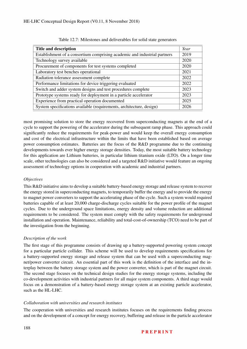
HE-LHC Conceptual Design Report (V0.11, 8 November 2018)
Table 12.7: Milestones and deliverables for solid state generators
Title and description YearEstablishment of a consortium comprising academic and industrial partners 2019Technology survey available 2020Procurement of components for test systems completed 2020Laboratory test benches operational 2021Radiation tolerance assessment complete 2022Performance limitations for device triggering evaluated 2022Switch and adder system designs and test procedures complete 2023Prototype systems ready for deployment in a particle accelerator 2023Experience from practical operation documented 2025System specifications available (requirements, architecture, design) 2026
most promising solution to store the energy recovered from superconducting magnets at the end of acycle to support the powering of the accelerator during the subsequent ramp phase. This approach couldsignificantly reduce the requirements for peak-power and would keep the overall energy consumptionand cost of the electrical infrastructure within the limits that have been established based on averagepower consumption estimates. Batteries are the focus of the R&D programme due to the continuingdevelopments towards ever higher energy storage densities. Today, the most suitable battery technologyfor this application are Lithium batteries, in particular lithium titanium oxide (LTO). On a longer timescale, other technologies can also be considered and a targeted R&D initiative would feature an ongoingassessment of technology options in cooperation with academic and industrial partners.
Objectives
This R&D initiative aims to develop a suitable battery-based energy storage and release system to recoverthe energy stored in superconducting magnets, to temporarily buffer the energy and to provide the energyto magnet power converters to support the accelerating phase of the cycle. Such a system would requiredbatteries capable of at least 20,000 charge-discharge cycles suitable for the power profile of the magnetcycles. Due to the underground space limitations, energy density and volume reduction are additionalrequirements to be considered. The system must comply with the safety requirements for undergroundinstallation and operation. Maintenance, reliability and total-cost-of-ownership (TCO) need to be part ofthe investigation from the beginning.
Description of the work
The first stage of this programme consists of drawing up a battery-supported powering system conceptfor a particular particle collider. This scheme will be used to develop requirements specifications fora battery-supported energy storage and release system that can be used with a superconducting mag-net/power converter circuit. An essential part of this work is the definition of the interface and the in-terplay between the battery storage system and the power converter, which is part of the magnet circuit.The second stage focuses on the technical design studies for the energy storage systems, including theco-development activities with industrial partners for all major system components. A third stage wouldfocus on a demonstration of a battery-based energy storage system at an existing particle accelerator,such as the HL-LHC.
Collaboration with universities and research institutes
The cooperation with universities and research institutes focuses on the requirements finding processand on the development of a concept for energy recovery, buffering and release in the particle accelerator
188P R E P R I N T
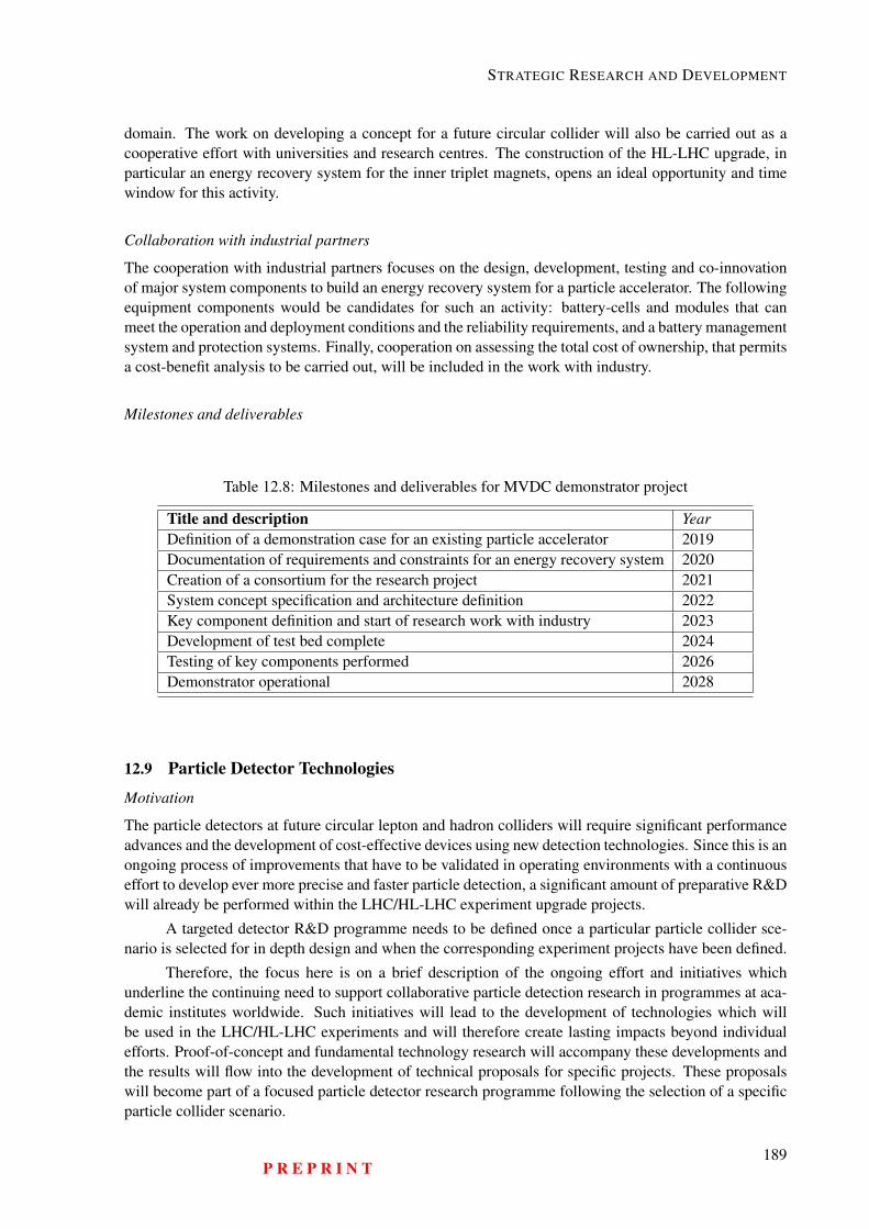
STRATEGIC RESEARCH AND DEVELOPMENT
domain. The work on developing a concept for a future circular collider will also be carried out as acooperative effort with universities and research centres. The construction of the HL-LHC upgrade, inparticular an energy recovery system for the inner triplet magnets, opens an ideal opportunity and timewindow for this activity.
Collaboration with industrial partners
The cooperation with industrial partners focuses on the design, development, testing and co-innovationof major system components to build an energy recovery system for a particle accelerator. The followingequipment components would be candidates for such an activity: battery-cells and modules that canmeet the operation and deployment conditions and the reliability requirements, and a battery managementsystem and protection systems. Finally, cooperation on assessing the total cost of ownership, that permitsa cost-benefit analysis to be carried out, will be included in the work with industry.
Milestones and deliverables
Table 12.8: Milestones and deliverables for MVDC demonstrator project
Title and description YearDefinition of a demonstration case for an existing particle accelerator 2019Documentation of requirements and constraints for an energy recovery system 2020Creation of a consortium for the research project 2021System concept specification and architecture definition 2022Key component definition and start of research work with industry 2023Development of test bed complete 2024Testing of key components performed 2026Demonstrator operational 2028
12.9 Particle Detector Technologies
Motivation
The particle detectors at future circular lepton and hadron colliders will require significant performanceadvances and the development of cost-effective devices using new detection technologies. Since this is anongoing process of improvements that have to be validated in operating environments with a continuouseffort to develop ever more precise and faster particle detection, a significant amount of preparative R&Dwill already be performed within the LHC/HL-LHC experiment upgrade projects.
A targeted detector R&D programme needs to be defined once a particular particle collider sce-nario is selected for in depth design and when the corresponding experiment projects have been defined.
Therefore, the focus here is on a brief description of the ongoing effort and initiatives whichunderline the continuing need to support collaborative particle detection research in programmes at aca-demic institutes worldwide. Such initiatives will lead to the development of technologies which willbe used in the LHC/HL-LHC experiments and will therefore create lasting impacts beyond individualefforts. Proof-of-concept and fundamental technology research will accompany these developments andthe results will flow into the development of technical proposals for specific projects. These proposalswill become part of a focused particle detector research programme following the selection of a specificparticle collider scenario.
P R E P R I N T189

HE-LHC Conceptual Design Report (V0.11, 8 November 2018)
Objectives
At CERN, a strategic R&D initiative, to define and organise the detector technology related researchactivities for the coming years, was launched in 2017 [332]. It covers the following topics:
1. Silicon sensors2. Gas detectors3. Calorimetry and light based detectors4. Mechanical supports for detectors5. Integrated circuits6. High-speed data links7. Simulation and analysis software8. Detector magnets
These technological aspects will be accompanied by detector performance studies in order to havea clear understanding of the improvement potential for various detection technologies and to be able toquantitatively document the further improvement potential and to identify potential limits of the varioustechnologies.
It is only at this stage the detector concepts that have been developed for the hadron and leptonparticle colliders can be simulated with a sufficient degree of fidelity. The results will give a betterunderstanding of the physics performance that can be expected and will identify the technological gapsand how they can be overcome. This activity will eventually lead to the specification of the function,performance, reliability and other qualitative requirements that form the foundation of the technicaldesign of the experiments.
Description of the work
The CERN coordinated detector technology research initiative spans a five-year period. Regular work-shops are already taking place (e.g. [333]) to develop the detailed research programme and to prioritisethe work together with an open, international consortium of academic institutes. The programme alsoaims to identify possible involvement of industrial partners from a very early stage so that it can be un-derstood which technologies can eventually be produced on an industrial scale and which technologiesindustry is particularly interested in.
The initiative is structured in several working groups (WG), each one focusing on a particulartechnological domain. This setup forms the nucleus of a converging activity of international researchinstitutions and universities which provides the opportunity to involve partners from all over the world.
The depleted CMOS technology attracts a lot of interest in the domain of silicon detectors (WG 1),as it allows low-mass and high-resolution sensors, which have the potential to cover large areas at af-fordable cost, to be built. In recent last years, substantial progress was achieved in terms of radiationhardness, a key requirement for all future experiments. Another trend is in low gain avalanche detectors(LGAD), which have achieved timing precision in the range of a few tens of picoseconds. Finally, thereis also a strong need to continue the development of classic silicon detectors (pixels, strips and pads) andthe associated electronics.
Gas detectors (WG 2) will continue to play an important role in future experiments as they cancover large areas at moderate cost. Micro pattern technologies have boosted their performance anda wealth of new ideas in terms of materials, production techniques and readout methods, show howthis success story can be pursued. An important question concerns the choice of the gases and theircompatibility with environmental standards.
Working group 3 deals with calorimetry and light based detectors, two topics often closely linked.One focus is on highly granular calorimeter concepts which allow the decomposition of jets into their
190P R E P R I N T
STRATEGIC RESEARCH AND DEVELOPMENT
individual particles (’particle flow calorimetry’). The requirements are manifold as are the options interms of active media (e.g. scintillators, noble liquids, silicon), absorbers and readout concepts. Accurateand high-precision timing is a key topic, too. In recent years, photosensors have been evolving rapidly.The silicon photomultiplier (SiPM) has matured and has become a standard tool for many applications.However, its high dark count rate and moderate radiation hardness limit its use when it comes to thedetection of low light levels, e.g. in Cherenkov detectors. This is still the domain of vacuum tubes,where emerging, finely segmented multi-anode devices, micro-channel plate tubes (for ultra-fast timing)and completely new concepts go far beyond the classic PMT.
Working group 4 on detector mechanics pursues the use of advanced materials, design tools andproduction technologies, which have the potential to change the way detectors are built and help to boosttheir performance. Ultra-light, precise and large size carbon-fibre components have become accessibleand permit the development of solutions which were inconceivable ten years ago. Environmentallyfriendly cooling technologies, combined with 3D printing and micro-fabrication technologies reduce theamount of material in vertex and tracking detectors. Close cooperation with industrial partners is seen asthe best way forward.
Working groups 5 and 6 deal with the development of application-specific electronics and high-rate, high throughput, data transmission for applications with severe constraints (radiation, power con-sumption, heat dissipation and space limits, accessibility, cable path limitations and more). The numbersof custom made chips in the LHC experiments is counted in millions and the high energy physics com-munity is considered to be an expert customer with very special requirements. The ever-decreasingsize feature in the CMOS manufacturing processes leads to benefits (higher functionality), but also toemerging behaviour (higher sensitivity to radiation, challenging cooling needs) and much higher costs(the number of transistors that can be obtained levelled out in around 2012 and since then it has starteddecreasing again. As a result of consolidation in industry fewer suppliers of very high density integra-tion devices exist and the competition across the market has decreased. The main challenges remain thestrongly increasing ionising doses and the necessity to read and transfer continuously increasing amountsof data.
Found at the other end of the data acquisition systems are the event filtering farms with theiradvanced software for pattern recognition, track reconstruction and other event selection processes. Thisis the topic covered by WG 7. New approaches to cope with the track reconstruction challenge at eventpile-up rates of 1000 and more (FCC-hh scenario) need to be developed. Machine learning is one topicthat needs to be investigated as a possible support technology for such challenges. Already more than tenthousand physicists world-wide use the software frameworks and algorithm toolkits produced by suchsoftware development initiatives. The Exabyte era, which is appearing on the horizon, calls for newconcepts to manage such amounts of data on a global scale throughout several decades of research.
Last but not least, WG 8 pursues the development of sustainable concepts for large high-fieldmagnets for the experiments. There is a study for FCC-ee of an ultra-thin 2 T magnet with a free boreof 4.4 m and 6 m lengths and a target material budget below 1 radiation length. The FCC-hh baselinedesign has a main solenoid with a free bore of 10 m and a length of 20 m and forward solenoids at bothends. All of these magnet developments require progress in superconducting wire technology.
Milestones and deliverables
The second workshop scheduled for autumn 2018 [334] concerns the writing of a report that summarisesthe focus and the priorities of the R&D programme. This roadmap will include the milestones anddeliverables for the initial five-year period.
P R E P R I N T191
HE-LHC Conceptual Design Report (V0.11, 8 November 2018)
12.10 Efficient Power Distribution InfrastructureMotivation
Power quality is a primary concern for all three of the colliders studied (FCC-hh, FCC-ee and HE-LHC).Achieving adequate availability to ensure efficient use of the new infrastructure, to avoid costly down-times and to achieve energy-efficient operation by reducing the need for recovery and restore actions isclosely linked to those parameters that determine power quality: transient voltage dip mitigation, reactivepower control, harmonic filtering and voltage stability. Switching from an alternating current (AC) dis-tribution network to a direct current (DC) power distribution in combination with local energy bufferingaddresses several of the key impact factors. Frequent transient power dips can be tolerated, active andreactive power can be compensated on the load side, AC harmonic filtering is not needed, distributionlosses are significantly reduced and larger spacing between electrical infrastructures compared to ACdistribution is permitted which leads to reduced infrastructure component investments.
Today, this technology is still in its infancy, mainly lacking adequate standardisation of operatingparameters and the availability of a set of equipment from different vendors due to its lack of widespreadadoption. Viable designs of electrical components for DC current and voltage switching, short-circuitcurrent switching, fault detection and protection system selectivity remain to be developed and stillrepresent technical challenges.
Objectives
The objective is to raise the readiness level of medium-voltage DC distribution network technology bydemonstrating its merits at CERN in close-cooperation with an industry-driven demonstrator project.This case serves as a platform for a consortium of industry partners to develop standards for this gridtechnology and to trigger the development of market-ready equipment. Technical challenges that stillremain to be addressed mainly concern electrical components for current and voltage switching andprotection elements such as short-circuit current switching, the detection of faults and an appropriateapproach to implement selective protection for the network (e.g. a fast fault-detection and protectioncommunication system to separate only the faulty element, maintaining overall high system reliability).This project aims at facilitating the acceptance of the technology among potential end-users in the com-modity market. Eventually, if this technology becomes wide-spread it will be available to large-scaleresearch infrastructure customers at the time when a future particle accelerator is to be installed.
Description of the work
The first phase to be carried out during a particle collider preparatory phase aims to establish a stableconsortium of companies who are active in standardisation bodies and who actively study the marketopportunities of commodity sectors, companies who have an interest in the development of key compo-nents and integrating them in a demonstrator at one of CERN’s accelerators. Universities and researchcentres that develop solutions for the technical challenges and who have the necessary experience shouldalso be part of this consortium. The first phase of the work consists in analyzing a specific use case toprovide power for one of CERN’s accelerators, the capture of the requirements and a detailed technicalgap analysis in cooperation with academic and industrial partners. In a second phase, consortium mem-bers draw up an architecture and propose a design for a demonstrator that includes the development ofnovel components to address the most critical technical challenges. In a third phase, prototypes of thetechnical components are developed by different contributors, fostering the co-development of academiaand industry. Finally, a demonstrator setup is installed at CERN that can also serve as a showcase forindustries to raise the acceptance of the technology at large scale. This work programme needs to beaccompanied with the conceptual and technical design work of a DC network for a specific particle col-lider scenario. This work can be based on the recommendation of the next European Srategy for ParticlePhysics update.
192P R E P R I N T
STRATEGIC RESEARCH AND DEVELOPMENT
Collaboration with universities and research institutes
MVDC distribution systems are an active area of academic research that spans various sectors includ-ing electrical engineering, electronics, information and computing technologies, reliability engineering,functional safety, economics and business analysis. Consequently, this is an ideal application to bringacademic partners with complementary competencies from different geographical regions together atCERN in a concrete technological research project with tangible impact potential at academic levels,with high-educational value and with opportunities to work in a close-to-market environment. Specifi-cally, EPFL (Lausanne, Switzerland), a technical university, has an active programme on the developmentof MVDC power distribution networks with support of the Swiss Federal Office of Energy (SFOE).
Collaboration with industrial partners
With the increasing availability of modern power electronics technologies such as switch-mode convert-ers with higher power ratings, DC networks are being increasingly considered for high voltage trans-mission lines (HVDC). DC networks start to be deployed for specific applications such as the supply ofpower for trains in underground metro transport facilities.
In addition to point to point and residential collection grids, MVDC is an interesting solution forindustrial applications due to its efficient operation, the small footprint and the low installation and op-erating costs. Companies like Hyundai, ABB, Siemens and Rolls-Royce are investigating the suitabilityof this technology for off-shore and maritime vessel applications as well as for heavy industries (e.g.aluminium manufacturing) and DC microgrids like those found in shopping centres, office blocks andin particular ever power hungry data centres, smart residential areas and also rural electrification. Sincethe technology is also ideal for integrating environmentally friendly power sources such as photovoltaicpanels (PV) and to a lesser extent fuel cells, companies that are active in the power generation market arealso starting to have an interest in this technology. The “EMerge Alliance” (www.emergealliance.org)built around this elusive technology is a mirror of who-is-who in the electrical industry and also theworld’s most important standardization organisations IEEE and ISO are involved in the ongoing activ-ities. Hence, this is an ideal opportunity for an international community with a vision for a large-scaleresearch infrastructure to provide a test-bed for academia and industry world-wide with the potential oflarge benefits for society and at the same time preparing the path for large-scale science infrastructuresto be operated in a sustainable fashion.
Initially, the focus can be on designing and standardising components, such as DC current break-ers, rectifiers, rectifier-transformer solutions and protection systems. The co-developments should lever-age existing application development efforts, such as DC railway systems.
Milestones and deliverables
P R E P R I N T193
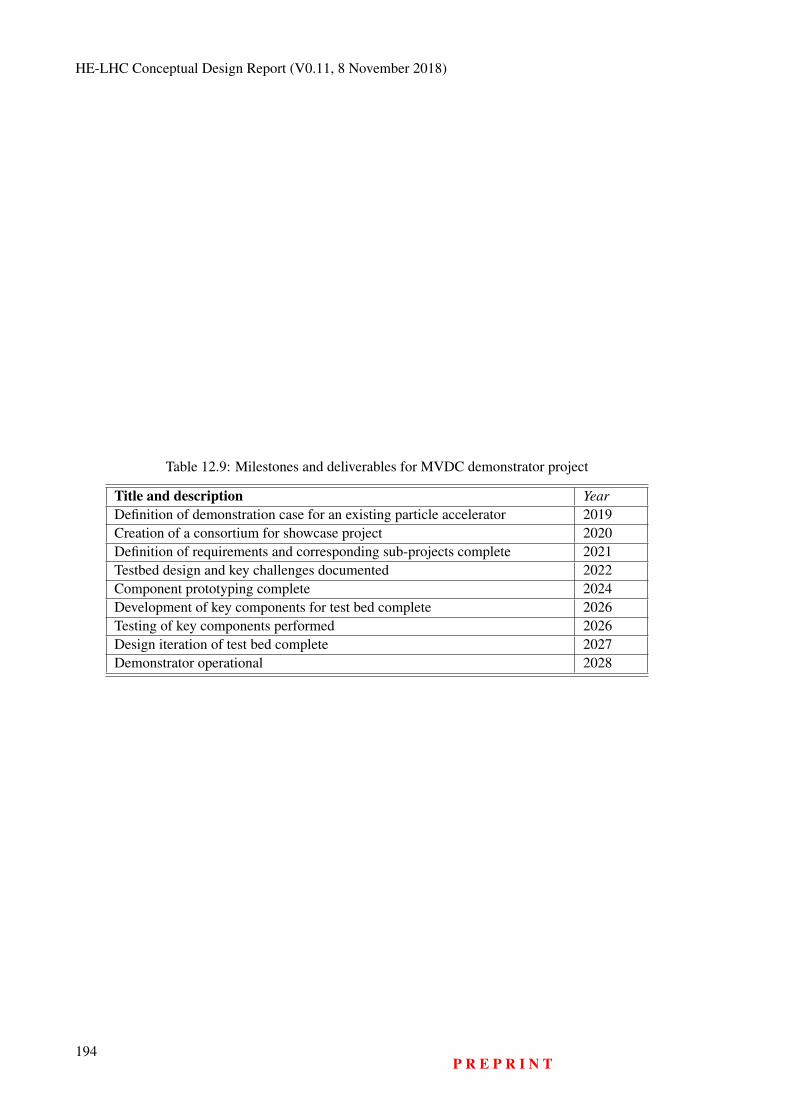
HE-LHC Conceptual Design Report (V0.11, 8 November 2018)
Table 12.9: Milestones and deliverables for MVDC demonstrator project
Title and description YearDefinition of demonstration case for an existing particle accelerator 2019Creation of a consortium for showcase project 2020Definition of requirements and corresponding sub-projects complete 2021Testbed design and key challenges documented 2022Component prototyping complete 2024Development of key components for test bed complete 2026Testing of key components performed 2026Design iteration of test bed complete 2027Demonstrator operational 2028
194P R E P R I N T

Chapter 13
Schedule Considerations
Appendices
195

HE-LHC Conceptual Design Report (V0.11, 8 November 2018)
196P R E P R I N T
Appendices A
Collider Parameter Tables
A ColliderB LHC as InjectorC Superconducting SPS
197

HE-LHC Conceptual Design Report (V0.11, 8 November 2018)
198P R E P R I N T
Appendices B
Experiment Parameter Tables
199

HE-LHC Conceptual Design Report (V0.11, 8 November 2018)
200P R E P R I N T

Appendices C
Uncertainties
This chapter summarises those uncertainties, which have the highest potentials of leading to adverseimpacts on the project scenario. They are grouped by technological and implementation-related un-certainties, depending on their origin. The information provided in this volume is a non-exhaustive,simplified assembly of risks, risk origins, impacts and mitigation measures, to give a glimpse of thecomprehensive risk management process, which has been set up and which is currently ongoing in thefuture circular collider study. A comprehensive risk assessment database is continuously maintained bythe study group in order to establish an early warning and mitigation process that is expected to growinto a comprehensive project risk management scheme during a preparatory phase project.
201
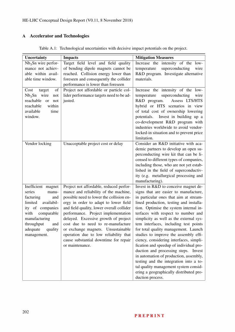
HE-LHC Conceptual Design Report (V0.11, 8 November 2018)
A Accelerator and Technologies
Table A.1: Technological uncertainties with decisive impact potentials on the project.
Uncertainty Impacts Mitigation MeasuresNb3Sn wire perfor-mance not achiev-able within avail-able time window.
Target field level and field qualityof bending dipole magnets cannot bereached. Collision energy lower thanforeseen and consequently the colliderperformance is lower than foreseen
Increase the intensity of the low-temperature superconducting wireR&D program. Investigate alternativematerials.
Cost target ofNb3Sn wire notreachable or notreachable withinavailable timewindow.
Project not affordable or particle col-lider performance targets need to be ad-justed.
Increase the intensity of the low-temperature superconducting wireR&D program. Assess LTS/HTShybrid or HTS scenarios in viewof total cost of ownership loweringpotentials. Invest in building up aco-development R&D program withindustries worldwide to avoid vendor-locked-in situation and to prevent pricelimitation.
Vendor locking Unacceptable project cost or delay Consider an R&D initiative with aca-demic partners to develop an open su-perconducting wire kit that can be li-censed to different types of companies,including those, who are not yet estab-lished in the field of superconductiv-ity (e.g. metallurgical processing andmanufacturing).
Inefficient magnetseries manu-facturing andlimited availabil-ity of companieswith comparablemanufacturingthroughput andadequate qualitymanagement.
Project not affordable, reduced perfor-mance and reliability of the machine,possible need to lower the collision en-ergy in order to adapt to lower fieldand field quality, lower overall colliderperformance. Project implementationdelayed. Excessive growth of projectcost due to need to re-manufactureor exchange magnets. Unsustainableoperation due to low reliability thatcause substantial downtime for repairor maintenance.
Invest in R&D to conceive magnet de-signs that are easier to manufacture,in particular ones that aim at stream-lined production, testing and installa-tion. Optimise the system internal in-terfaces with respect to number andsimplicity as well as the external sys-tem interfaces, including test pointsfor total quality management. Launchstudies to improve the assembly effi-ciency, considering interfaces, simpli-fication and speedup of individual pro-duction and processing steps. Investin automation of production, assembly,testing and the integration into a to-tal quality management system consid-ering a geographically distributed pro-duction process.
202P R E P R I N T
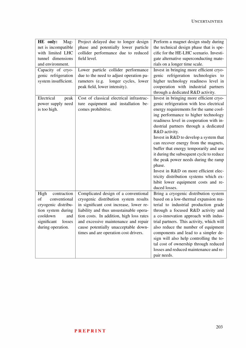
UNCERTAINTIES
HE only: Mag-net is incompatiblewith limited LHCtunnel dimensionsand environment.
Project delayed due to longer designphase and potentially lower particlecollider performance due to reducedfield level.
Perform a magnet design study duringthe technical design phase that is spe-cific for the HE-LHC scenario. Investi-gate alternative superconducting mate-rials on a longer time scale.
Capacity of cryo-genic refrigerationsystem insufficient.
Lower particle collider performancedue to the need to adjust operation pa-rameters (e.g. longer cycles, lowerpeak field, lower intensity).
Invest in bringing more efficient cryo-genic refrigeration technologies tohigher technology readiness level incooperation with industrial partnersthrough a dedicated R&D activity.
Electrical peakpower supply needis too high.
Cost of classical electrical infrastruc-ture equipment and installation be-comes prohibitive.
Invest in bringing more efficient cryo-genic refrigeration with less electricalenergy requirements for the same cool-ing performance to higher technologyreadiness level in cooperation with in-dustrial partners through a dedicatedR&D activity.Invest in R&D to develop a system thatcan recover energy from the magnets,buffer that energy temporarily and useit during the subsequent cycle to reducethe peak power needs during the rampphase.Invest in R&D on more efficient elec-tricity distribution systems which ex-hibit lower equipment costs and re-duced losses.
High contractionof conventionalcryogenic distribu-tion system duringcooldown andsignificant lossesduring operation.
Complicated design of a conventionalcryogenic distribution system resultsin significant cost increase, lower re-liability and thus unsustainable opera-tion costs. In addition, high loss ratesand excessive maintenance and repaircause potentially unacceptable down-times and are operation cost drivers.
Bring a cryogenic distribution systembased on a low-thermal expansion ma-terial to industrial production gradethrough a focused R&D activity anda co-innovation approach with indus-trial partners. This activity, which willalso reduce the number of equipmentcomponents and lead to a simpler de-sign will also help controlling the to-tal cost of ownership through reducedlosses and reduced maintenance and re-pair needs.
P R E P R I N T203
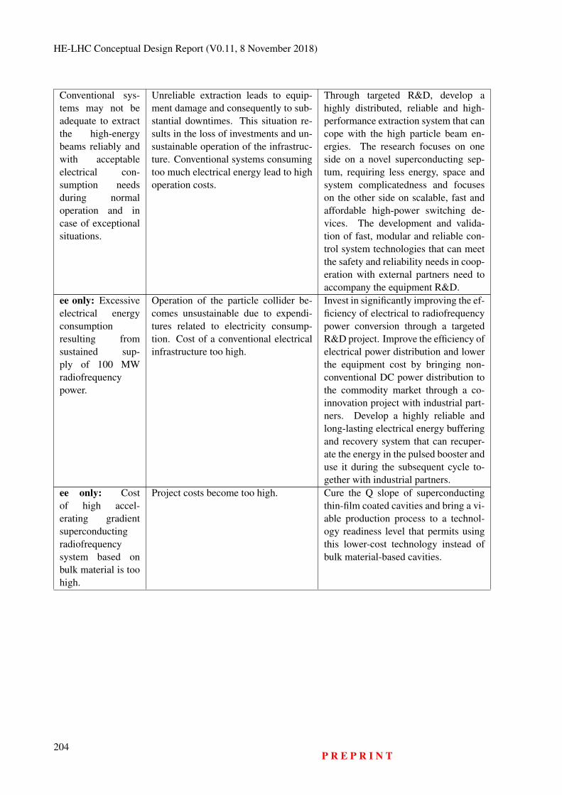
HE-LHC Conceptual Design Report (V0.11, 8 November 2018)
Conventional sys-tems may not beadequate to extractthe high-energybeams reliably andwith acceptableelectrical con-sumption needsduring normaloperation and incase of exceptionalsituations.
Unreliable extraction leads to equip-ment damage and consequently to sub-stantial downtimes. This situation re-sults in the loss of investments and un-sustainable operation of the infrastruc-ture. Conventional systems consumingtoo much electrical energy lead to highoperation costs.
Through targeted R&D, develop ahighly distributed, reliable and high-performance extraction system that cancope with the high particle beam en-ergies. The research focuses on oneside on a novel superconducting sep-tum, requiring less energy, space andsystem complicatedness and focuseson the other side on scalable, fast andaffordable high-power switching de-vices. The development and valida-tion of fast, modular and reliable con-trol system technologies that can meetthe safety and reliability needs in coop-eration with external partners need toaccompany the equipment R&D.
ee only: Excessiveelectrical energyconsumptionresulting fromsustained sup-ply of 100 MWradiofrequencypower.
Operation of the particle collider be-comes unsustainable due to expendi-tures related to electricity consump-tion. Cost of a conventional electricalinfrastructure too high.
Invest in significantly improving the ef-ficiency of electrical to radiofrequencypower conversion through a targetedR&D project. Improve the efficiency ofelectrical power distribution and lowerthe equipment cost by bringing non-conventional DC power distribution tothe commodity market through a co-innovation project with industrial part-ners. Develop a highly reliable andlong-lasting electrical energy bufferingand recovery system that can recuper-ate the energy in the pulsed booster anduse it during the subsequent cycle to-gether with industrial partners.
ee only: Costof high accel-erating gradientsuperconductingradiofrequencysystem based onbulk material is toohigh.
Project costs become too high. Cure the Q slope of superconductingthin-film coated cavities and bring a vi-able production process to a technol-ogy readiness level that permits usingthis lower-cost technology instead ofbulk material-based cavities.
204P R E P R I N T
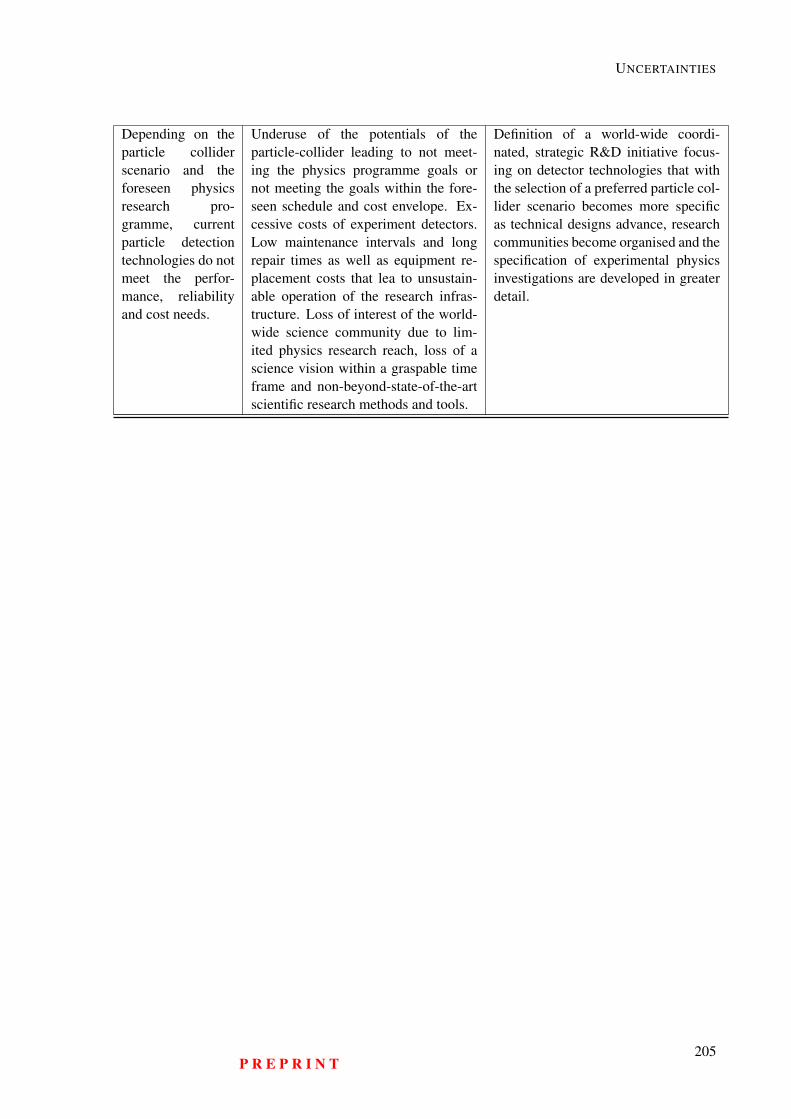
UNCERTAINTIES
Depending on theparticle colliderscenario and theforeseen physicsresearch pro-gramme, currentparticle detectiontechnologies do notmeet the perfor-mance, reliabilityand cost needs.
Underuse of the potentials of theparticle-collider leading to not meet-ing the physics programme goals ornot meeting the goals within the fore-seen schedule and cost envelope. Ex-cessive costs of experiment detectors.Low maintenance intervals and longrepair times as well as equipment re-placement costs that lea to unsustain-able operation of the research infras-tructure. Loss of interest of the world-wide science community due to lim-ited physics research reach, loss of ascience vision within a graspable timeframe and non-beyond-state-of-the-artscientific research methods and tools.
Definition of a world-wide coordi-nated, strategic R&D initiative focus-ing on detector technologies that withthe selection of a preferred particle col-lider scenario becomes more specificas technical designs advance, researchcommunities become organised and thespecification of experimental physicsinvestigations are developed in greaterdetail.
P R E P R I N T205
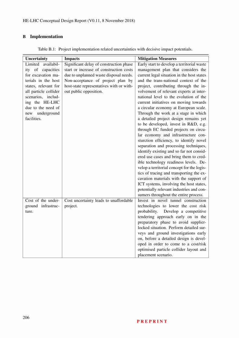
HE-LHC Conceptual Design Report (V0.11, 8 November 2018)
B Implementation
Table B.1: Project implementation related uncertainties with decisive impact potentials.
Uncertainty Impacts Mitigation MeasuresLimited availabil-ity of capacitiesfor excavation ma-terials in the hoststates, relevant forall particle colliderscenarios, includ-ing the HE-LHCdue to the need ofnew undergroundfacilities.
Significant delay of construction phasestart or increase of construction costsdue to unplanned waste disposal needs.Non-acceptance of project plan byhost-state representatives with or with-out public opposition.
Early start to develop a territorial wastemanagement plan that considers thecurrent legal situation in the host statesand the trans-national context of theproject, contributing through the in-volvement of relevant experts at inter-national level to the evolution of thecurrent initiatives on moving towardsa circular economy at European scale.Through the work at a stage in whicha detailed project design remains yetto be developed, invest in R&D, e.g.through EC funded projects on circu-lar economy and infrastructure con-sturction efficiency, to identify novelseparation and processing techniques,identify existing and so far not consid-ered use cases and bring them to cred-ible technology readiness levels. De-velop a territorial concept for the logis-tics of tracing and transporting the ex-cavation materials with the support ofICT systems, involving the host states,potentially relevant industries and con-sumers throughout the entire process.
Cost of the under-ground infrastruc-ture.
Cost uncertainty leads to unaffordableproject.
Invest in novel tunnel constructiontechnologies to lower the cost riskprobability. Develop a competitivetendering approach early on in thepreparatory phase to avoid supplier-locked situation. Perform detailed sur-veys and ground investigations earlyon, before a detailed design is devel-oped in order to come to a cost/riskoptimised particle collider layout andplacement scenario.
206P R E P R I N T
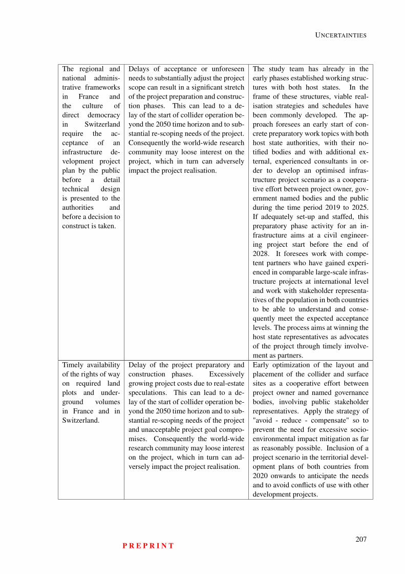
UNCERTAINTIES
The regional andnational adminis-trative frameworksin France andthe culture ofdirect democracyin Switzerlandrequire the ac-ceptance of aninfrastructure de-velopment projectplan by the publicbefore a detailtechnical designis presented to theauthorities andbefore a decision toconstruct is taken.
Delays of acceptance or unforeseenneeds to substantially adjust the projectscope can result in a significant stretchof the project preparation and construc-tion phases. This can lead to a de-lay of the start of collider operation be-yond the 2050 time horizon and to sub-stantial re-scoping needs of the project.Consequently the world-wide researchcommunity may loose interest on theproject, which in turn can adverselyimpact the project realisation.
The study team has already in theearly phases established working struc-tures with both host states. In theframe of these structures, viable real-isation strategies and schedules havebeen commonly developed. The ap-proach foresees an early start of con-crete preparatory work topics with bothhost state authorities, with their no-tified bodies and with additional ex-ternal, experienced consultants in or-der to develop an optimised infras-tructure project scenario as a coopera-tive effort between project owner, gov-ernment named bodies and the publicduring the time period 2019 to 2025.If adequately set-up and staffed, thispreparatory phase activity for an in-frastructure aims at a civil engineer-ing project start before the end of2028. It foresees work with compe-tent partners who have gained experi-enced in comparable large-scale infras-tructure projects at international leveland work with stakeholder representa-tives of the population in both countriesto be able to understand and conse-quently meet the expected acceptancelevels. The process aims at winning thehost state representatives as advocatesof the project through timely involve-ment as partners.
Timely availabilityof the rights of wayon required landplots and under-ground volumesin France and inSwitzerland.
Delay of the project preparatory andconstruction phases. Excessivelygrowing project costs due to real-estatespeculations. This can lead to a de-lay of the start of collider operation be-yond the 2050 time horizon and to sub-stantial re-scoping needs of the projectand unacceptable project goal compro-mises. Consequently the world-wideresearch community may loose intereston the project, which in turn can ad-versely impact the project realisation.
Early optimization of the layout andplacement of the collider and surfacesites as a cooperative effort betweenproject owner and named governancebodies, involving public stakeholderrepresentatives. Apply the strategy of"avoid - reduce - compensate" so toprevent the need for excessive socio-environmental impact mitigation as faras reasonably possible. Inclusion of aproject scenario in the territorial devel-opment plans of both countries from2020 onwards to anticipate the needsand to avoid conflicts of use with otherdevelopment projects.
P R E P R I N T207
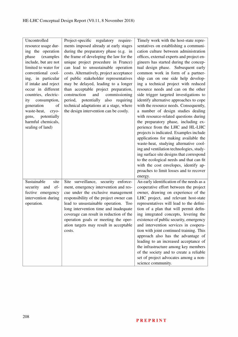
HE-LHC Conceptual Design Report (V0.11, 8 November 2018)
Uncontrolledresource usage dur-ing the operationphase (examplesinclude, but are notlimited to water forconventional cool-ing, in particularif intake and rejectoccur in differentcountries, electric-ity consumption,generation ofwaste-heat, cryo-gens, potentiallyharmful chemicals,sealing of land)
Project-specific regulatory require-ments imposed already at early stagesduring the preparatory phase (e.g. inthe frame of developing the law for theunique project procedure in France)can lead to unsustainable operationcosts. Alternatively, project acceptanceof public stakeholder representativesmay be delayed, leading to a longerthan acceptable project preparation,construction and commissioningperiod, potentially also requiringtechnical adaptations at a stage, wherethe design intervention can be costly.
Timely work with the host-state repre-sentatives on establishing a communi-cation culture between administrationoffices, external experts and project en-gineers has started during the concep-tual design phase. Subsequent earlycommon work in form of a partner-ship can on one side help develop-ing a technical project with reducedresource needs and can on the otherside trigger targeted investigations toidentify alternative approaches to copewith the resource needs. Consequently,a number of design studies dealingwith resource-related questions duringthe preparatory phase, including ex-perience from the LHC and HL-LHCprojects is indicated. Examples includeapplications for making available thewaste-heat, studying alternative cool-ing and ventilation technologies, study-ing surface site designs that correspondto the ecological needs and that can fitwith the cost envelopes, identify ap-proaches to limit losses and to recoverenergy.
Sustainable sitesecurity and ef-fective emergencyintervention duringoperation.
Site surveillance, security enforce-ment, emergency intervention and res-cue under the exclusive managementresponsibility of the project owner canlead to unsustainable operation. Toolong intervention time and inadequatecoverage can result in reduction of theoperation goals or meeting the oper-ation targets may result in acceptablecosts.
An early identification of the needs as acooperative effort between the projectowner, drawing on experience of theLHC project, and relevant host-staterepresentatives will lead to the defini-tion of a plan that will permit defin-ing integrated concepts, levering theexistence of public security, emergencyand intervention services in coopera-tion with joint continued training. Thisapproach also has the advantage ofleading to an increased acceptance ofthe infrastructure among key membersof the society and to create a reliableset of project advocates among a non-science community.
208P R E P R I N T

UNCERTAINTIES
Cost-effectivenessand quality of sup-plied materials andservices due to ex-cessive constraintson public tenderingprocesses. This in-cludes limitationsof a well-definedcost/performancebased procurementscheme for theproject, ineffec-tive internationalnetworks withindustries andpotential suppliersof all sizes, toomuch generic focuson either in-houseor out-sourcedservices, insuf-ficient personnel(in-house or con-tracted) resourcesfor procurement,contract followupand inadequatebusiness processesas well as a lack oflegal advisors withextensive industrialexperience duringpeak periods.
High administrative efforts resulting inlengthy and costly procurement pro-cesses impact project preparation andconstruction phase durations. These inturn can lead to the selection of under-performing suppliers. This leads inthe long run to potentially unaccept-able high total costs of ownership (re-construction of subsystems, high repairor maintenance costs, high operationcosts)
Timely preparation of an adequate pro-curement and academia/industry co-development framework. Timely in-vestment in preparing the ground forwell staffed project procurement fora limited period of time, respect-ing the different needs during dif-ferent phases of the project lifecy-cle (preparation, CE construction, ma-chine construction, commissioning).Timely development of an appropri-ate concept for in-kind participation ofmember-states and non-member stateswith a corresponding project gover-nance and management structure thatincludes effective levers to proceedwith the implementation of the project(early stall warning, re-prioritization,re-scheduling, re-assignment).
P R E P R I N T209
HE-LHC Conceptual Design Report (V0.11, 8 November 2018)
Availability ofstable structuresdriving forward thetechnical design ofa particle colliderscenario, of theassociated experi-ment detectors, thehost state activitiesand the financingstrategy.
The lack of a priority vision, whichis further developed in the frameworkof a defined governance and man-agement structure with adequate re-source assignment leads to a stall inthe progress of the technical designs,the development of mitigtation mea-sures of the identified uncertainties andfails to strengthen the momentum ofan ever growing international commu-nity, which is a pre-requisite of a re-search infrastructure project of suchscale. Consequently, investments madeso far and being made for limited ac-tivities cannot result in lasting impacts.Consequently the research communitymay choose to re-orient towards alter-native project opportunities.
With the next update of the Euro-pean strategy for particle physics, anadequate governance and preparatoryproject phase management structureneeds to be established for the acceler-ator and infrastructure project and fora particle detector design project that iswell anchored in CERN’s structure andmission program, which has the meansand personnel resources to adequatelycarry out the planned tasks before a de-cision to build is taken. Consequently,the successful preparation of a new re-search infrastructure for high-energyparticle physics relies on the unam-biguous recommendation that emergesfrom the next strategy update, permit-ting to focus the available resources onthose tasks, which need to be accom-plished with highest priority.
210P R E P R I N T

Glossary
Ω The ohm is the SI derived unit of electrical resistance.
4DCHM 4-Dimensional Composite Higgs Model.
A The ampere (symbol: A) is the base unit of electric current in the International System of Units(SI).
A15 A15 phases are series of intermetallic compounds with the chemical formula A3B, where A is atransition metal and B can be any element. Many of these compounds have superconductivity ataround 20 K and remain superconducting in magnetic fields of tens of Teslas. One example forsuch a compound is Nb3Sn.
ab An attobarn corresponds to an area equal to 10-46 m2.
ABCI The Azimuthal Beam Cavity Interaction is software which solves the Maxwell equations directlyin the time domain when a bunched beam goes through an axi-symmetric structure on or off axis.An arbitrary charge distribution can be defined by the user.
AC Alternating Current.
a-C Amorphous Carbon.
ADC Analogue-to-Digital Converter.
ADT The ADT is a transverse damping system deployed in the LHC to reduce the oscillations of theinjected proton beam, to reduce emittance blow-up due to ground motion and magnetic noise orripple and to stabilise the beam against the resistive wall instability and other possible instabilitiescaused by narrow band parasitic transverse impedances in the ring.
Alcove An alcove is a recessed area open from a larger room but enclosed by walls, pillars, or otherarchitectural elements.
AMD Adiabatic Matching Device.
APC Artificial Pinning Centres.
Ar Argon is a chemical element with symbol Ar and atomic number 18.
Arc A circular collider is composed of bent cells called arcs that are separated by straight sections (seeLSS). An arc half-cell forms the periodic part of the arc lattice (see lattice).
ARIES An H2020 EC funded research and development project in the area of particle accelerator tech-nologies.
ARMCO American Rolling Mill Company pure iron became synonymous with the purest steel millproduced iron with a purity of more than 99.85 % Fe.
ASIC An Application-Specific Integrated Circuit is an integrated circuit (IC) customised for a particularuse, rather than intended for general-purpose use.
211
HE-LHC Conceptual Design Report (V0.11, 8 November 2018)
ATLAS A Toroidal LHC ApparatuS is one of the seven particle detector experiments constructed at theLarge Hadron Collider.
B The byte is a unit of digital information that most commonly consists of eight bits, representing abinary number.
b The bit, a binary digit, is a basic unit of information used in computing and digital communications.A binary digit can have only one of two values, and may be physically represented with a two-statedevice.
Bi The dispersion function of a beam line is determined by the strength and placement of dipolemagnets. As a consequence, dipole field errors also contribute to the dispersion function. Multipolecomponents corresponding to a magnetic flux distribution, which can be added up are denoted byBi and Ai. B1 corresponds to a normal dipole component, B2 to a normal quadrupole component,B3 to a normal sextupole component, A1 to a skew dipole, A2 to a skew quadrupole and A3 to askew sectupole..
barn A barn (symbol: b) is a unit of area equal to 10-28 m2. It is best understood as a measure of theprobability of interaction between small particles. A barn is approximately the cross-sectional areaof a uranium nucleus.
BCS BardeenâASCooperâASSchrieffer theory (named after John Bardeen, Leon Cooper, and JohnRobert Schrieffer) is the first microscopic theory of superconductivity since Heike KamerlinghOnnes’s 1911 discovery. The theory describes superconductivity as a microscopic effect causedby a condensation of Cooper pairs into a boson-like state.
Be Beryllium is a rare chemical element with symbol Be and atomic number 4.
Beam pipe Volumes of different shape (e.g. cylindrical, conical, flanges and bellows) and material (e.g.metallic, ceramic) used to transport the beam. The contained ultrahigh-vacuum reduces beam-gasinteractions to a level at which the beam lifetime is acceptable.
Beamline A series of functional elements, such as magnets and vacuum pipe, which carry the beamfrom one portion of the accelerator to another.
Beamscreen Perforated tube inserted into the cold bore of the superconducting magnets in order toprotect the cold bore from synchrotron radiation and ion bombardment.
Beta function An optical function proportional to the square of the local transverse beam size. Thebeta function details how the beam width changes around the accelerator. There are separate Κfunctions for the x and y planes.
B-factory A B-factory, or sometimes a beauty factory, is a particle collider experiment designed toproduce and detect a large number of B mesons so that their properties and behaviour can bemeasured with small statistical uncertainty. Tauons and D mesons are also copiously produced atB-factories.
BFPP Bound-Free Pair Production is one of the new types of processes that occur in relativistic col-lisions of atoms and ions. It is the production of an electron-positron pair with the electron notproduced as a free state but as a bound state of one of the ions.
Bhabha scattering The electron-positron scattering process: e+e− → e+e− There are two leading-order Feynman diagrams contributing to this interaction: an annihilation process and a scatteringprocess.
BHWIDE A Monte Carlo event generator software simulating Bhabha-scattering, developed for linearcollider detector luminosity studies.
BIM Building information modeling is a process involving the generation and management of digitalrepresentations of physical and functional characteristics of places.
212P R E P R I N T

Glossary
BLM Beam Loss Monitor.
BPM Beam Position Monitor.
Bq The becquerel is the SI derived unit of radioactivity. One becquerel is defined as the activityof a quantity of radioactive material in which one nucleus decays per second. The becquerel istherefore equivalent to an inverse second, s1.
BR In particle physics and nuclear physics, the branching ratio for a decay is the fraction of particleswhich decay by an individual decay mode with respect to the total number of particles whichdecay.
BR (machine) The Booster Ring is an accelerator in the collider tunnel, which provides the particlecollider continuously with particles at collision energy.
BRGM Bureau de Recherches Géologiques et Minières, France.
BS Beamstrahlung.
BSCCO Bismuth strontium calcium copper oxide (pronounced "bisko"), is a family of high-temperaturesuperconductors. Specific types of BSCCO are usually referred to using the sequence of the num-bers of the metallic ions. Thus Bi-2201 is the n = 1 compound (Bi2Sr2CuO6+x), Bi-2212 is the n= 2 compound (Bi2Sr2CaCu2O8+x), and Bi-2223 is the n = 3 compound (Bi2Sr2Ca2Cu3O10+x)..
BSM Beyond Standard Model.
Bunch A group of particles captured inside a longitudinal phase space bucket.
BX Bunch crossing.
C The coulomb (symbol: C) is the International System of Units (SI) unit of electric charge. It is thecharge (symbol: Q or q) transported by a constant current of one ampere in one second.
C band The C band is a designation by the Institute of Electrical and Electronics Engineers (IEEE) fora part of the microwave band of the electromagnetic spectrum covering frequencies from 4 to 8gigahertz.
C++ An object-oriented programming language.
CAD Computer-Aided Design is the use of computer systems to aid in the creation, modification, anal-ysis, or optimisation of a design.
CAF A Compressed Air Foam system is used in firefighting to deliver fire retardant foam for the purposeof extinguishing a fire or protecting unburned areas.
CAPEX Capital expenditures are the funds used to acquire or upgrade fixed assets, such as expenditurestowards property, plant, or equipment.
Carnot Efficiency Carnot efficiency describes the maximum thermal efficiency that a heat engine canachieve as permitted by the Second Law of Thermodynamics.
CBA Cost-benefit analys is a systematic process for estimating and comparing benefits and costs of aproject. The purpose of CBA is to facilitate a more efficient allocation of resources, demonstratingthe convenience for society of a particular intervention rather than possible alternatives.
CC60 The CC60 facility at CERN uses a 60Co source for the qualification of components against TIDeffects.
CCT A Canted-Cosine-Theta magnet is an accelerator magnet that superposes fields of nested and tiltedsolenoids that are oppositely canted.
CDR A Conceptual Design Report completes the first stage of the ESFRI roadmap methodology, per-mitting concept screening, consortium formation, access policy and funding concept preparation,scientific and project leadership definition.
P R E P R I N T213

HE-LHC Conceptual Design Report (V0.11, 8 November 2018)
CEA The French Alternative Energies and Atomic Energy Commission (Commissariat à’ l’énergieatomique et aux énergies).
CepC The Circular Electron Positron Collider is an electron-positron collider proposed by the Chinesehigh energy physics community, acting as a Higgs-factory in a new tunnel 80 to 100 km in length.
CEREMA The French ’Centre d’Etude et d’Expertise sur les Risques, l’Environnement, la Mobilitéet l’Aménagement’ is a public administration organisation, governed by the ’ministre chargé del’écologie, du développement durable et de l’énergie’ and the ‘ministre du transport, de l’égalitédes territoires et de la ruralité’. The organisation works with the territorial state services during alldevelopment projects, notably with respect to implement sustainable development goals (urban-ism, environment, infrastructures and transport, risk management).
CERN European Organisation for Nuclear Research.
CETU The ‘Centre d’études des tunnels’ is a technical service of the French ‘ministère de l’Écologie,du Développement et de la Mer’, a notified body for the safety of tunnels in France.
CFC Carbon Fibre Composite.
CFD Computational Fluid Dynamics uses numerical analysis to solve and analyse problems that involvefluid flows.
CH4 Methane is a chemical compound.
CHARM Cern High energy AcceleRator Mixed field facility, located in the CERN East Area, suppliesa wide spectrum of radiation types and energies.
CHF ISO code of the Swiss franc currency.
Chilled Water Chilled water is a commodity used to cool a building’s air and equipment. It’s tempera-ture is between 4°C and 7°C.
CIR Circuit.
CIXP CERN Internet eXchange Point.
CL Confidence Level.
CLD The CLic Detector is a conceptual design for an experiment detector at Compact Linear Collider,which also serves as a design model for an experiment detector at the FCC-ee.
CLIC The Compact Linear Collider (CLIC) is a concept for a future linear electron-positron collider ina new tunnel, ranging from 11 to 50 km, depending on the collision energy.
CLIC-dp The CLIC detector and physics study is an international collaboration currently composed of30 institutions.
CLIQ The Coupling-Loss-Induced Quench method is a superconducting magnet protection approach.
CM Cold Mass.
CMM Coordinated measuring machines.
CMOS Complementary metal oxide semiconductor is a technology for constructing integrated circuitspatented in 1963 by Frank Wanlass while working for Fairchild Semiconductor.
CMS The Compact Muon Solenoid is one of the seven particle detector experiments constructed at theLarge Hadron Collider.
CNDP The French ‘Commission nationale du débat public’ was created in 1995 and is since 2002 anindependent administration authority. The organisation ensures that the public participates in theprocess of construction projects of national interest.
CNES The National Centre for Space Studies is the French government’s space agency.
CNRS The French National Center for Scientific Research (Centre national de la recherche scientifique).
214P R E P R I N T
Glossary
COL Collimation.
Collimator A device that removes beam particles at large amplitudes. They are used to keep beam-losses low and to protect critical elements of the accelerator.
Collision A close encounter of particles during which dynamic quantities such as energy, momentum,and charge may be exchanged.
Comsol A cross-platform, finite element analysis, solver and multiphysics simulation software devel-oped by private company COMSOL Inc. (Sweden). It allows conventional physics-based userinterfaces and coupled systems of partial differential equations.
Cooper pair Two electrons that appear to ”team up” in accordance with theory, BCS or other, despitethe fact that they both have a negative charge and normally repel each other. Below the supercon-ducting transition temperature, paired electrons form a condensate, a macroscopically occupiedsingle quantum state, which flows without resistance. However, since only a small fraction of theelectrons are paired, the bulk does not qualify as being a ”bose-einstein condensate”.
COTS Commercial-Off-The-Shelf.
CP Charge conjugation parity symmetry is the product of two symmetries: C for charge conjugation,which transforms a particle into its antiparticle, and P for parity, which creates the mirror imageof a physical system. The strong interaction and electromagnetic interaction seem to be invariantunder the combined CP transformation operation, but this symmetry is slightly violated duringcertain types of weak decay. Historically, CP-symmetry was proposed to restore order after thediscovery of parity violation in the 1950s.
Cr2O3 Chromium(III) oxide is an inorganic compound. It is one of the principal oxides of chromiumand is used as a pigment. In nature, it occurs as the rare mineral eskolaite.
Critical temperature Temperature Tc below which characteristics of superconductivity appear. Thevalue varies from material to material and depends on the magnetic field.
Cryo magnet Complete magnet system integrated into one cryostat, including main magnet coils, col-lars and cryostat, correction magnets and powering circuits.
Cryogenic system A system that operates below a temperature set by convention at 150 K (-123.15C).
CST Computer Simulation Technology is a computational tool from Dassault Systems for 3D electro-magnetic design and analysis.
Cu Copper is a chemical element with symbol Cu and atomic number 29.
CW A Continuous Wave is an electromagnetic wave of constant amplitude and frequency, almost al-ways a sine wave, that for mathematical analysis is considered to be of infinite duration.
Cybersecurity Cybersecurity is the protection of computer systems from theft or damage to their hard-ware, software or electronic data, as well as from disruption or misdirection of the services theyprovide.
DA Dynamic Aperture.
DAΦNE The Double Annular Φ Factory for Nice Experiments is an electron-positron collider at theINFN Frascati National Laboratory in Frascati, Italy. It has been colliding electrons and positronsat a centre of mass energy of 1.02 GeV to create φ mesons Since 1999.
DAQ Data Acquisition.
Dark matter Invisible matter that makes up 26% of the universe and which can only be detected fromits gravitational effects. Only 4% of the matter in the Universe are visible. The remaining 70% areaccounted to dark energy.
dB The decibel (symbol: dB) is a unit of measurement used to express the ratio of one value of a
P R E P R I N T215
HE-LHC Conceptual Design Report (V0.11, 8 November 2018)
physical property to another on a logarithmic scale. When expressing power quantities, the numberof decibels is ten times the logarithm to base 10 of the ratio of two power quantities. That is, achange in power by a factor of 10 corresponds to a 10 dB change in level.
DC Direct Current.
DCAL Digital hadron calorimeter.
DCCT A Direct Current-Current Transformer is a current-to-voltage transducer, employed when mea-surement of very high current is required.
DCH Drift CHamber.
DD4hep A Detector Description toolkit for High Energy Physics.
DELPHES Delphes is a C++ framework, performing a fast multipurpose detector response simulation.The simulation includes a tracking system, embedded into a magnetic field, calorimeters and amuon system.
DELPHI The Detector with Lepton, Photon and Hadron Identification was one of the four main detec-tors of the Large Electron-Positron Collider (LEP) at CERN.
DESY The German Electron Synchrotron (Deutsches Elektronen-Synchrotron).
DFAE The Département Fédéral des Affaires Étrangères is the Swiss foreign ministry.
Dipole A magnet with two poles, like the north and south poles of a horseshoe magnet. Dipoles are usedin particle accelerators to keep particles moving in a circular orbit.
DIS Dispersion suppressor.
DM Dark Matter.
DN Diametre Nominal, the European equivalent of Nominal Pipe Size (NPS) defines a set of nominalpipe sizes in standard ISO 6708. The dimensionless number after the letters DN indicate thephysical size in millimetres of the bore.
DOE The United States Department of Energy.
DPA Displacement Per Atom.
DR A Damping Ring reduces the emittances produced by the particle source to the small values re-quired for the collider. Emittance reduction is achieved via the process of radiation damping, i.e.the combination of synchrotron radiation in bending fields with energy gain in RF cavities.
DRAM Dynamic Random-Access Memory.
DVR Dynamic Voltage Restorer.
Dynamic aperture Maximum transverse oscillation amplitude that guarantees stable particle motionover a given number of turns. If the motion amplitude of a particle exceeds this threshold, thebetatron oscillation of the particle will not have any bounds, and the motion will become unstable,leading to loss of the particle. It is expressed in multiples of the beam size together with theassociated number of turns. Unlike the physical aperture, dynamic aperture separating stable andunstable trajectories is not a hard boundary.
Dynistor A dynistor is an unidirectional thyristor breakover diode. It can be used as switches in micro-and nanosecond power pulse generators.
EASITrain An H2020 EC funded Marie Słodovska Curie Innovative Training Network project to ad-vance superconducting wire and thin film technologies as well as cryogenic refrigeration systemsfor particle accelerators.
EBITDA A company’s Earnings Before Interest, Taxes, Depreciation, and Amortisation is an account-ing measure calculated using a company’s net earnings, before interest expenses, taxes, depreci-
216P R E P R I N T
Glossary
ation, and amortisation are subtracted, as a proxy for a company’s current operating profitability(i.e., how much profit it makes with its present assets and its operations on the products it producesand sells, as well as providing a proxy for cash flow.
EC Electron Cloud.
ECal Electromagnetic Calorimeter (also ECAL).
ECFA European Committee for Future Accelerators.
EDLC Electrical Double-Layer Capacitors.
EES Energy Extraction System.
EFT An Effective Field Theory is a type of approximation, or effective theory, for an underlying physi-cal theory, such as a quantum field theory or a statistical mechanics model.
EHF ElectroHydraulic Forming is a type of metal forming in which an electric arc discharge in liquidis used to convert electrical energy to mechanical energy and change the shape of the workpiece.
EIA Environmental Impact Assessment.
EIE Étude de l’impact sur l’environnement is the Swiss name for the environmental impact assessmentin the scope of the OEIE.
EIR Experimental Insertion Region.
Electron cloud A cloud of electrons generated inside an accelerator beam pipe due to gas ionisation,photoemission from synchrotron radiation, or ”beam-induced multipacting” via electron acceler-ation in the field of the beam and secondary emission. Electron clouds may cause single- andmulti-bunch beam instabilities as well as additional heat load on the beam screen inside the coldmagnets.
electronvolt In physics, the electronvolt (symbol eV, also written electron-volt and electron volt) is aunit of energy equal to approximately 1.6× 10âLŠ19 joules (symbol J) in SI units. By definition, itis the amount of energy gained (or lost) by the charge of a single electron moving across an electricpotential difference of one volt. The electronvolt is not an SI unit, and its definition is empirical.By mass-energy equivalence, the electronvolt is also a unit of mass, expressed in units of eV/c2,where c is the speed of light in vacuum.
Electroweak symmetry breaking Although electromagnetism and the weak force have the same strengthat high energies, electromagnetism is much stronger than the weak force in our everyday experi-ence. The mechanism by which, at low energies, a single unified electroweak force appears as twoseparate forces is called electroweak symmetry breaking.
EM Electro Magnetic.
EMB Electromagnetic barrel calorimeter.
EMEC Endcap electromagnetic calorimeter.
EMF Forward electromagnetic calorimeter.
Emittance The area in phase space occupied by a particle beam. The units are mm-milliradians fortransverse emittance and eV·sec for longitudinal emittance.
EN European Norms are documents that have been ratified by one of the three European Standard-ization Organizations (ESOs), CEN, CENELEC or ETSI; recognised as competent in the area ofvoluntary technical standardisation as for the EU Regulation 1025/2012.
EOT The most common type of overhead crane, found in many factories. These cranes are electricallyoperated by a control or remote control pendant, or from an operator cabin attached to the crane.
EPFL The École polytechnique fédérale de Lausanne is one of the two Swiss Federal Institutes ofTechnology.
P R E P R I N T217
HE-LHC Conceptual Design Report (V0.11, 8 November 2018)
ERL Energy Recovery Linac.
ERMC Enhanced Racetrack Model Coil.
ES Electro Static.
ESD Electron-Stimulated Desorption.
ESFRI European Strategy Forum for Research Infrastructures.
Espoo Convention The Espoo Convention sets out the obligations of Parties to assess the environmentalimpact of certain activities at an early stage of planning. It also lays down the general obligationof States to notify and consult each other on all major projects under consideration that are likelyto have a significant adverse environmental impact across boundaries.
ESPP European Strategy for Particle Physics. See also https://europeanstrategy.cern.
ESRF The European Synchrotron Radiation Facility is a joint research facility situated in Grenoble,France, and supported by 22 countries (13 member countries: France, Germany, Italy, UK, Spain,Switzerland, Belgium, The Netherlands, Denmark, Finland, Norway, Sweden, Russia and 9 asso-ciate countries: Austria, Portugal, Israel, Poland, Czech Republic, Hungary, Slovakia, India andSouth Africa).
ESS Energy Storage System.
ETHZ The Eidgenössische Technische Hochschule Zürich is one of the two Swiss Federal Institutes ofTechnology.
EU European Union.
EuCARD02 A FP7 EC funded research and development project in the area of particle acceleratortechnologies.
EuroCirCol An H2020 EC funded research and development project to develop the foundations of afuture circular hadron collider.
EW Electroweak.
EWPO Electroweak Precision Observables.
EWPT Electroweak Phase Transition.
EWSB Electroweak Symmetry Breaking.
EXP Experiment.
Experiment insertion region Place in the particle collider hosting the interaction region in which thetwo beams are brought to collision and the surrounding particle physics experiments.
EXT Extraction.
fb A femtobarn corresponds to an area equal to 10-43 m2.
FCC Future Circular Collider is a feasibility study aiming at the development of conceptual designsfor future energy and high-intensity frontier particle colliders based on a technically feasible andaffordable circular layout permitting staged implementation.
FCC-ee Future circular intensity-frontier electron-positron collider with multiple centre-of-mass colli-sion energies ranging from the Z peak to tt collision energies at luminosities up to almost 5×1036
cm−2s−1 in a new circular tunnel of about 100 km length.
FCC-eh Future circular energy-frontier electron-hadron collider interaction point scenario. The sce-nario foresees an energy recovery linac (ERL) to generate electron beams and to collide them withhigh-energetic proton or ion beams of a hadron collider in a new circular tunnel of about 100 kmlength.
218P R E P R I N T
Glossary
FCC-hh Future circular energy-frontier hadron-hadron collider reaching up to 100 TeV centre-of-masscollision energies at luminosities of 5 − 10 × 1034 cm−2s−1. Operation with protons and ions isenvisaged.
FED Fractional Effective Dose.
FEM European Federation of Material Handling.
FF Final Focus.
FIB A FIB setup is a scientific instrument that resembles a scanning electron microscope (SEM). How-ever, while the SEM uses a focused beam of electrons to image the sample in the chamber, a FIBsetup uses a focused beam of ions instead.
FinFET A Fin Field Effect Transistor is a type of non-planar or "3D" transistor used in the design ofmodern processors.
FLUKA A particle physics Monte Carlo simulation package for high energy experimental physics andengineering, shielding, detector and telescope design, cosmic ray studies, dosimetry, medicalphysics and radio-biology.
Flux pinning The phenomenon where a magnet’s lines of force (called flux) become trapped or ”pinned”inside a superconducting material. This pinning binds the superconductor to the magnet at a fixeddistance. Flux-pinning is only possible when there are defects in the crystalline structure of thesuperconductor (usually resulting from grain boundaries or impurities). Flux-pinning is desirablein high-temperature ceramic superconductors in order to prevent ”flux-creep”, which can create apseudo-resistance and depress Jc and Hc.
FMA Radioactive waste of ‘Faible et moyenne activité’ (low and intermediate activity), the classifica-tion depends on the level of activity and on the radionuclides.
FMECA The Failure Mode, Effects, and Criticality Analysis is a bottom-up, inductive analytical methodwhich may be performed at either the functional or piece-part level. It is used to chart the prob-ability of failure modes against the severity of their consequences. The result highlights failuremodes with relatively high probability and severity of consequences, allowing remedial effort tobe directed where it will produce the greatest value.
FNAL Fermi National Accelerator Laboratory.
FODO The FOcusing and DefOcusing cell is a widespread lattice concept for designing a particle ac-celerator based on a magnet structure consisting alternately of focusing and defocusing quadrupolelenses.
FPC Fixed Power Coupler.
FPGA A Field-Programmable Gate Array is an integrated circuit designed to be configured by a cus-tomer or a designer after manufacturing.
FSI Frequency Scanning interferometry.
GB A gigabyte is by definition of the IEC, 109 B.
Gd Gadolinium is a chemical element with symbol Gd and atomic number 64.
Gd2O3 Gadolinium(III) oxide is an inorganic compound. It is one of the most commonly availableforms of the rare-earth element gadolinium, derivatives of which are potential contrast agents formagnetic resonance imaging.
GEANT4 GEANT4 is a platform for the simulation of the passage of particles through matter using MonteCarlo methods. It is the successor of the GEANT series of software toolkits developed by CERN.
GeniLac A project planned in Geneva to use the water of lake Geneva for cooling and heating of publicbuildings and international organisations.
P R E P R I N T219
HE-LHC Conceptual Design Report (V0.11, 8 November 2018)
GESDEC The ‘Service de géologie, sols et déchets’ is the office of the canton and state of Geneva incharge of questions related to excavation materials, ground acquisition and classification, protec-tion of underground volumes and underground water.
GeV 109 electronvolt.
GHz 109 Hz.
Gif++ The Gamma Irradiation Facility is located in the CERN North Area. It combines a 137Cs sourcewith a high-energy particle beam from the SPS H4 beam line.
GIM In quantum field theory, the GIM mechanism (or Glashow-Iliopoulos-Maiani mechanism) is themechanism through which flavour-changing neutral currents (FCNCs) are suppressed in loop dia-grams. It also explains why weak interactions that change strangeness by 2 are suppressed, whilethose that change strangeness by 1 are allowed, but only in charged current interactions.
GIS Geographical Information System.
GNSS The Global Navigation Satellite System is the standard generic term for satellite navigation sys-tems that provide autonomous geo-spatial positioning with global coverage. This term includese.g. the GPS, GLONASS, Galileo, Beidou and other regional systems.
GRI A Global Research Infrastructure is mandated by the G8+5 and addresses worldwide science andtechnology challenges, following the ”GSO Framework for Global Research Infrastructures”. TheGSO maintains a list of potential GRIs.
GRN Geodetic Reference Network.
GSO Group of Senior Officials mandated by G8+5 to develop GRI concepts.
GTO A gate turn-off thyristor (GTO) is a special type of thyristor, which is a high-power semiconduc-tor device. It acts as a bistable switch, conducting when the gate receives a current trigger, andcontinuing to conduct until the voltage across the device is reversed biased, or until the voltageis removed. GTOs, as opposed to normal thyristors, are fully controllable switches which can beturned on and off by their third lead, the gate lead.
Guinea-Pig++ An electron-positron beam-beam simulation software developed at CERN.
GV 109 volt.
GV (vacuum) Gate Valve.
Gy The gray (symbol: Gy) is a derived unit of ionising radiation dose in the International System ofUnits (SI). It is defined as the absorption of one joule of radiation energy per kilogram of matter.
H The Higgs boson (symbol: H) is an elementary particle in the Standard Model of particle physics,produced by the quantum excitation of the Higgs field. The particle has a spin of 0.
H2020 Horizon 2020 is an EU Research and Innovation funding programme over 7 years (2014 to2020). It is the financial instrument implementing the ”Innovation Union”, a Europe 2020 flagshipinitiative aimed at securing Europe’s global competitiveness.
Hc The scientific notation representing the ”critical field” or maximum magnetic field that a super-conductor can endure before it is ”quenched” and returns to a non-superconducting state. Usuallya higher Tc also brings a higher Hc.
ha The hectare is an SI accepted metric system unit of area equal to a square with 100 metre sides, or1 ha = 10,000 m2.
Hadron A subatomic particle that contains quarks, antiquarks, and gluons, and so experiences the strongforce. The proton is the most common hadron.
HB Barrel hadron calorimeter.
220P R E P R I N T
Glossary
HCAL Hadron calorimeter.
HCal Hadron Calorimeter.
HEB High Energy Booster.
HEC Endcap hadron calorimeter.
HEH High Energy Hadron fluence, i.e. hadrons with energies greater than 20 MeV.
HEIKA The High Efficiency International Klystron Activity was initiated at CERN in 2014 to evaluateand develop new bunching technologies for high-efficiency klystrons.
HEL Hollow Electron Lens.
HE-LHC High-energy Large Hadron collider. A new particle collider with about twice the LHC colli-sion energy in the existing LHC tunnel, using technologies conceived for the FCC-hh.
HERA The Hadron-Elektron-Ringanlage (English: Hadron-Electron Ring Accelerator) was a particleaccelerator at DESY in Hamburg. It began operating in 1992. At HERA, electrons or positronswere collided with protons at a center of mass energy of 318 GeV. It was the only lepton-protoncollider in the world while operating. HERA was closed down on 30 June 2007.
HF Hadron forward calorimeter.
HFSS A 3D electromagnetic simulation software for designing and simulating high-frequency elec-tronic products from ANSYS.
HIE-ISOLDE The High-Intensity and Energy upgrade of ISOLDE project incorporates a new linearaccelerator (Linac) into CERN’s ISOLDE facility (which stands for the Isotope mass SeparatorOn-Line DEvice).
Higgs boson An elementary particle linked with a mechanism to model, how particles acquire mass.
HiRadMat The High-Radiation to Materials facility at CERN provides high-intensity pulsed beams toan irradiation area where material samples as well as accelerator component assemblies can betested.
HL-LHC High Luminosity upgrade of the LHC to a levelled constant luminosity of 5 × 1034 cm2s−1.A dedicated FP7 design study (HiLumi LHC DS) precedes the implementation of the upgrade.
HLS Hydrostatic Levelling System.
HLT High Level Trigger.
HOM Higher Order Modes are undesired Eigenmodes parasitically excited in a resonant (accelerating)radiofrequency cavity.
HTML Hypertext Markup Language.
HTS High Temperature Superconductors have critical temperatures above 77 K.
HTTP HyperText Transfer Protocol.
HV High Voltage.
HVDC High Voltage Direct Current power distribution.
HX Heat eXchanger.
Hz The hertz (symbol: Hz) is the derived unit of frequency in the International System of Units (SI)and is defined as one cycle per second.
IBS Iron-based superconductors (IBS) are iron-containing chemical compounds whose superconduct-ing properties were discovered in 2006.
IC Integrated Circuit.
ICS Inverse Compton Scattering.
P R E P R I N T221
HE-LHC Conceptual Design Report (V0.11, 8 November 2018)
ICT Information and Communications Technology.
IDEA The International Detector for Electron Accelerator is a conceptual design for an experimentdetector at the FCC-ee.
IEEE The Institute of Electrical and Electronics Engineers is is the world’s largest association of tech-nical professionals. Its objectives are the educational and technical advancement of electrical andelectronic engineering, telecommunications, computer engineering and allied disciplines.
ILC The International Linear Collider (ILC) is a proposed linear electron-positron particle collideraiming at collision energies of 500 GeV and an upgrade to 1000 GeV (1 TeV).
Impedance A quantity that quantifies the self-interaction of a charged particle beam, mediated by thebeam environment, such as the vacuum chamber, RF cavities, and other elements encounteredalong the accelerator or storage ring.
INFN Istituto Nazionale di Fisica Nucleare.
INJ Injection.
Innovation New ideas that respond to societal or economic needs and generate new products, services,business and organisational models that are successfully introduced into an existing market andare able to create new markets and that contribute value to society.
Invar Invar, also known generically as FeNi36 (64FeNi in the US), is a nickel-iron alloy notable forits uniquely low coefficient of thermal expansion (CTE). The name Invar comes from the wordinvariable, referring to its relative lack of expansion or contraction with temperature changes. Itwas invented in 1896 by Swiss physicist Charles Édouard Guillaume. He received the Nobel Prizein Physics in 1920 for this discovery, which enabled improvements in scientific instruments.
IP Interaction Point.
IPC Incoherent Pair Creation.
IR Interaction Region.
IrCe Iridium-Cerium is an alloy used as a photocathode.
ISD Ion-Stimulated Desorption.
ISO The International Organization for Standardisation is an international standard-setting body com-posed of representatives from various national standards organizations.
IT Information Technology.
ITER ITER is an international nuclear fusion research and engineering project. It is an experimentalTokamak fusion reactor that is being built next to the Cadarache facility in Saint-Paul-lèz-Durance,in Provence, southern France.
ITS Inner Tracking System.
J The joule (symbol: J) is a derived unit of energy in the International System of Units. It is equal tothe energy transferred to or work done on an object when a force of one newton acts on that objectin the direction of its motion through a distance of one metre. It is also the energy dissipated asheat when an electric current of one ampere passes through a resistance of one ohm for one second.
Jc The scientific notation representing the ”critical current density” or maximum current that a su-perconductor can carry. As the current flowing through a superconductor increases, the Tc willusually decrease.
JLab Thomas Jefferson National Accelerator Facility (TJNAF), commonly called Jefferson Lab or JLab.
K See Kelvin.
222P R E P R I N T

Glossary
kB A kilobyte refers traditionally to 1024 bytes. In december 1998, the IEC defined 210 = 1024 bytesas 1 kibiyte (KiB).
KEKB KEKB is a particle accelerator used in the Belle experiment to study CP violation. KEKB islocated at the KEK (High Energy Accelerator Research Organisation) in Tsukuba, Ibaraki Prefec-ture, Japan.
Kelvin Unit of measurement for temperature (K) using as null point the absolute zero, the temperatureat which all thermal motion ceases. 0 K = −273.15Celsius.
keV 103 electronvolt.
kg The kilogram or kilogramme (symbol: kg) is the base unit of mass in the International System ofUnits (SI), and is defined as being equal to the mass of the International Prototype of the Kilogram(IPK, also known as ”Le Grand K” or ”Big K”), a cylinder of platinum-iridium alloy stored by theInternational Bureau of Weights and Measures at Saint-Cloud, France.
KLOE A particle physics experiment at the INFN Frascati National Laboratory, Italy.
KlyC Software developed at CERN for the optimisation and design of high efficiency Klystrons basedon new bunching mechanisms.
Klystron A specialised linear-beam vacuum tube, which is used as an amplifier for high radio frequen-cies.
Kr Krypton is a chemical element with symbol Kr and atomic number 36.
kW 103 Watt.
l The litre (SI spelling) or liter (American spelling) (symbol l in this document) is an SI acceptedmetric system unit of volume equal to 1,000 cubic centimetres or 1/1,000 cubic metre.
L* tbd.
LAL Laboratoire de l’accélérateur linéaire (LAL) of CNRS in Orsay in France.
LAr Liquid Argon.
LASE Laser-Ablated Surface Engineering.
Lattice The arrangements of quadrupoles, dipole magnets, drift spaces and higher-order magnetic ele-ments in the optical description of an accelerator.
LCBI Longitudinal Coupled Bunch Instability.
LCCS Local Chromatic Correction System.
LEP The Large Electron–Positron Collider, which was operated at CERN until 2000.
LEP3 A concept for an electron-positron collider in the existing LHC tunnel with a centre-of-mass of240 GeV and a peak luminosity of 1× 1034 cm−2s−1 at each of two experiments.
Lepton A class of elementary particles that do not experience the strong force. The electron is the mostcommon lepton.
LF Low Field.
LFV Lepton Flavour Violation.
LGAD Low Gain Avalanche Detectors.
LHC The Large Hadron Collider is a circular particle collider for protons and heavy ions with a designcentre-of-mass energy of 14 TeV for proton-proton collisions at a peak luminosity of 1 × 1034
cm2s−1 at CERN in Geneva, Switzerland.
LHCb The Large Hadron Collider beauty experiment is one of the seven particle detector experimentsconstructed at the Large Hadron Collider.
P R E P R I N T223
HE-LHC Conceptual Design Report (V0.11, 8 November 2018)
LHeC A study to extend the current LHC collider with an energy recovery linac (ERL) to generateelectron beams and to collide them with high-energetic proton or ion beams of the LHC.
LIL LEP Injector Linac.
Linac A LINear ACcelerator for charged particles in which a number of successive radiofrequency cav-ities that are powered and phased such that the particles passing through them receive successiveincrements of energy.
Linac4 The linear accelerator 4 at CERN accelerates negative hydrogen ions (H−, consisting of a hydro-gen atom with an additional electron) to 160 MeV to prepare them to enter the Proton SynchrotronBooster (PSB), which is part of the LHC injection chain.
LIU LHC Injector Upgrade.
LLRF Low Level RF.
LN2 Liquid nitrogen is nitrogen in a liquid state at an extremely low temperature.
LSP Lightest Supersymmetric Particle.
LSS Long Straight Section: quasi-straight segments of a circular collider, which are available for beaminteractions or utility insertions (e.g. injection, extraction, collimation, RF).
LTO Lithium Titanium Oxide.
LTS Low Temperature Superconductors have critical temperatures below 77 K.
Luminometer A calorimeter inside the detector to precisely measure the luminosity.
Luminosity Luminosity is the rate of collision events normalised to the cross section. It is expressed asinverse square centimetre and inverse second (cm−2s−1) or barn (1 barn = 10−24 cm2).
LV Low Voltage.
MAC Media access control is a sublayer of the data link layer (DLL) in the seven-layer OSI networkreference model. MAC is responsible for the transmission of data packets to and from the network-interface card, and to and from another remotely shared channel.
MAD-X MAD-X is a project and computational physics software to aid particle accelerator design andsimulation.
MADX-PTC MAD X Polymorphic Tracking Code.
MAPS Monolithic Active Pixel Sensor. A silicon detector technology for high-energy physics particledetectors.
MB A megabyte are by definition of the IEC, 1,000,000 bytes (106 B).
MC Monte Carlo.
MCHF 106 CHF.
MD (magnet) Main Dipole.
MDI The Machine Detector Interface refers to the topics and regions where the beamlines of the accel-erator overlap with the physics experiment’s detector. Key elements include mechanical support offinal beamline elements, luminosity monitoring, feedback, background suppression and radiationshielding.
MDISim A tool set developed in the frame of the FCC study for Machine Detector Interface SIMulationsusing and combining the standard tools MAD-X, ROOT and GEANT4.
MDT Monitored Drift Tube.
MEG A particle physics experiment at the Paul Scherrer Institute, Switzerland.
MeV 106 electronvolt.
224P R E P R I N T
Glossary
MgB2 Magnesium diboride is the inorganic compound. It is a dark gray, water-insoluble solid. Thecompound becomes superconducting at 39 K.
MGy 106 gray.
MHz 106 Hz.
MI Microwave Instability.
MIIT Millions of amp squared seconds. A performance indicator of a superconducting cable that deter-mines two primary factors of the adequate quench protection system: how quickly the current inthe magnet must be reduced once a quanch is detected and how quickly a quench must be detected,once the initiating spot quenches.
MJ 106 joule.
MLI Multi Layer Insulation.
mm 10−3 m.
MO Main Octupole corrector magnet.
MolfFlow+ Software developed at CERN to calculate the pressure in an arbitrarily complex geometrywhen ultra-high vacuum condition is met.
MOSFET Metal-Oxide-Semiconductor Field-Effect Transistor.
MoU Memorandum of Understanding.
MP Medium Pressure, around 20 bar.
MPGD Micro Pattern Gas Detector.
MQ Main Quadrupole.
MQDA Main Quadrupole Dispersion supressor magnet.
MQS Main Quadrupole Skew magnet.
MQT Main Quadrupole Tuning magnet.
MQTL Main Quadrupole Trim manget.
MRI Magnetic Resonance Imaging.
MRN Metrologial Reference Network.
MS Main Sextupole.
MTE Multi Turn Extraction.
MTTF Mean Time To Failure.
MTTR Mean Time To Repair.
MVDC Medium Voltage Direct Current power distribution.
MW 106 Watt.
N The newton (symbol: N) is the SI unit of force. A newton is how much force is required to makea mass of one kilogram accelerate at a rate of one metre per second squared.
NASA National Aeronautics and Space Administration.
Nb Niobium, formerly known as columbium, is a chemical element with symbol Nb (formerly Cb)and atomic number 41. It is a soft, grey, crystalline, ductile transition metal, often found in theminerals pyrochlore and columbite, hence the former name ”columbium”. Niobium is used invarious superconducting materials.
Nb3Sn A metallic chemical compound of niobium (Nb) and tin (Sn). An LTS with Tc = 18.3 K that canwithstand magnetic field intensities up to 30 Tesla.
P R E P R I N T225

HE-LHC Conceptual Design Report (V0.11, 8 November 2018)
NbTi Niobium-titanium is an alloy of niobium and titanium, used industrially as a type II supercon-ductor wire for superconducting magnets, normally as Nb-Ti fibres in an aluminium or coppermatrix.
NEG Non-Evaporable Getter materials are mostly porous alloys or powder mixtures of Al, Zr, Ti, V andiron (Fe). They help to establish and maintain vacuums by soaking up or bonding to gas moleculesthat remain within a partial vacuum.
Nelium A light gas mixture made of neon and helium.
Net Present Value NPV is a measurement of profit calculated by subtracting the present values (PV) ofcash outflows (including initial cost) from the present values of cash inflows over a period of time.It is determined by calculating the costs (negative cash flows) and benefits (positive cash flows) foreach period of an investment. After the cash flow for each period is calculated, the PV of each oneis obtained by discounting its future value at a periodic rate of return.
NEXTorr A patented flanged vacuum pumping solution, combining NEG and ion pumping technologiesby the saes group, Milan, Italy.
NIE The Notice d’Impact sur l’Environnement is an assembly of the results of environmental impactassessments for large projects in Switzerland.
NMR Nuclear Magnetic Resonance.
NN Neural Network.
NTU The Number of Transfer Units is defined as a ratio of the overall thermal conductance to thesmaller heat capacity rate. It may also be interpreted as the relative magnitude of the heat transferrate compared to the rate of enthalpy change of the smaller heat capacity rate fluid.
NuPECC Nuclear Physics European Collaboration Committee.
O Big O notation is a mathematical notation that describes the limiting behavior of a function whenthe argument tends towards a particular value or infinity.
OBS Organisation Breakdown Structure.
ODH Oxygen Deficiency Hazard.
OEIE The Ordonnance relative à’ l’étude de l’impact sur l’environnement is the Swiss environmentalimpact assessment regulation.
OFHC Oxygen-free copper (OFC) or oxygen-free high thermal conductivity (OFHC) copper is a groupof wrought high conductivity copper alloys that have been electrolytically refined to reduce thelevel of oxygen to 0.001% or below.
OPEX An operating expense, operating expenditure, operational expense, operational expenditure oropex is an ongoing cost for running a product, business, or system.
Optics An optical configuration refers to a powering scheme of the magnets. There can be severaldifferent optics for a single lattice configuration. Different optics exist for instance, for injectionand for luminosity operation corresponding to different β∗ values in the experiment insertions.
ORC The Organic Rankine Cycle is named for its use of an organic, high molecular mass fluid with aliquid-vapor phase change, or boiling point, occurring at a lower temperature than the water-steamphase change. The fluid allows Rankine cycle heat recovery from lower temperature sources. Thelow-temperature heat is converted into useful work, that can itself be converted into electricity.
OSI The Open Systems Interconnection model is a conceptual model that characterises and standardisesthe communication functions of a telecommunication or computing system without regard to itsunderlying internal structure and technology.
OSI Model The Open Systems Interconnection Model is a conceptual and logical layout that defines
226P R E P R I N T
Glossary
network communication used by systems open to interconnection and communication with othersystems.
Overburden Material (rock, soil) that lies above an underground structure, e.g. a tunnel or cavern..
Pa The pascal is the SI derived unit of pressure. A common multiple unit of the pascal us the hec-topascal (1 hPa = 100 Pa) which is equal to one millibar.
Pandora PFA The Pandora Particle Flow Algorithm is an event reconstruction software developed forfuture linear collider studies ILC and CLIC.
Pb Lead is a chemical element with symbol Pb (from the Latin plumbum) and atomic number 82.
PBR The Pre Booster Ring is an injector to the booster top-up ring (BR), which continuously providesthe particle collider with particles at collision energy.
PBS Product Breakdown Structure.
PCB Printed Circuit Board.
PCO Power COnverter.
PDF The Parton name was proposed by Richard Feynman in 1969 as a generic description for anyparticle constituent within the proton, neutron and other hadrons. These particles are referredtoday as quarks and gluons. A Parton Distribution Function is defined as the probability densityfor finding a particle with a certain longitudinal momentum fraction at a certain resolution scale.
PEDD Peak Energy Deposition Density.
PEP-II The PEP-II facility consists of two independent storage rings, one located atop the other in theat the Stanford Linear Accelerator Center (SLAC). The high-energy ring, which stores a 9-GeVelectron beam, was an upgrade of the existing Positron-Electron Project (PEP) collider; it reused allof the PEP magnets and incorporated a state-of-the-art copper vacuum chamber and a new radio-frequency system capable of supporting a stored beam of high current. The low-energy ring, whichstores 3.1-GeV positrons, was newly constructed. Injection is achieved by extracting electrons andpositrons at collision energies from the SLC and transporting them each in a dedicated bypass line.The low-emittance Stanford Linear Collider (SLC) beams are used for the injection process. Thecollider was completed in July 1998.
PERLE Powerful Energy Recovery Linac for Experiments, an envisaged test facility for an energyrecovery linac (ERL) at Laboratoire de l’accélérateur linéaire (LAL) of CNRS in Orsay in France.
PFL Pulse Forming Line.
PFN Pulse Forming Network.
pH A logarithmic scale used to specify the acidity or basicity of an aqueous solution. It is approx-imately the negative of the base 10 logarithm of the molar concentration, measured in units ofmoles per liter, of hydrogen ions.
Phase Space A six-dimensional space consisting of a particle’s position (x, y, z) and divergence (x′, y′,z′). Phase space is represented in two dimensions by plotting position on the horizontal axis andthe corresponding divergence on the vertical axis.
PHY In the seven-layer OSI model of computer networking, the physical layer or layer 1 is the firstand lowest layer. This layer may be implemented by a dedicated PHY chip. The physical layerconsists of the electronic circuit transmission technologies of a network.
pileup The situation where a particle detector is affected by several events at the same time.
PIT The Powder-In-Tube process is often used for making electrical conductors from brittle supercon-ducting materials such as niobium-tin or magnesium diboride and ceramic cuprate superconductorssuch as BSCCO.
P R E P R I N T227
HE-LHC Conceptual Design Report (V0.11, 8 November 2018)
PLC Programmable Logic Controller.
PMNS The Pontecorvo-Maki-Nakagawa-Sakata matrix, Maki-Nakagawa-Sakata matrix (MNS matrix),lepton mixing matrix, or neutrino mixing matrix is a unitary mixing matrix which contains infor-mation on the mismatch of quantum states of neutrinos when they propagate freely and when theytake part in the weak interactions. It is a model of neutrino oscillation. This matrix was introducedin 1962 by Ziro Maki, Masami Nakagawa and Shoichi Sakata, to explain the neutrino oscillationspredicted by Bruno Pontecorvo..
PMT Photomultiplier tube.
pNGB pseudo Nambu-Goldstone Boson.
PoT Protons On Target.
PPLP Parabolic Parabolic Linear Parabolic.
ppm Parts per million (10−6).
PS The Proton Synchrotron is a particle accelerator at CERN. It was CERN’s first synchrotron, begin-ning operation in 1959. It has since served as a pre-accelerator for the Intersecting Storage Rings(ISR) and the Super Proton Synchrotron (SPS), and is currently part of the Large Hadron Collider(LHC) accelerator complex. In addition to protons, PS has accelerated alpha particles, oxygen andsulphur nuclei, electrons, positrons and antiprotons.
PSB The Proton Synchrotron Booster at CERN is an accelerator made up of four superimposed syn-chrotron rings that receive beams of protons from the linear accelerator Linac 2 or 4 at 50 MeVand accelerate them to 1.4 GeV for injection into the Proton Synchrotron (PS).
PSD Photon Stimulation Desorption is a phenomenon whereby a substance is released from or througha surface.
PSO In computational science, particle swarm optimisation is a computational method that optimisesa problem by iteratively trying to improve a candidate solution with regard to a given measure ofquality. It solves a problem by having a population of candidate solutions, here dubbed particles,and moving these particles around in the search-space according to simple mathematical formulaeover the particle’s position and velocity. Each particle’s movement is influenced by its local bestknown position, but is also guided toward the best known positions in the search-space, whichare updated as better positions are found by other particles. This is expected to move the swarmtoward the best solutions.
PU Pileup.
PV Photovoltaics.
PVSS Prozessvisualisierungs- und Steuerungssoftware. A SCADA product from SIEMENS companyETM Professional Control now called WinCC OA.
Px One of the 12 FCC access points. x can be one of A, B, C, D, E, F, G, H, I, J, K, L, e.g. PA is theaccess point A close to the CERN Meyrin site.
PyHEADTAIL A macroparticle tracking software designed specifically to simulate collective effects incircular accelerators.
Pythia A Monte Carlo event generator software.
Q The quality factor or Q factor is a dimensionless parameter that describes how underdamped anoscillator or resonator is, and characterises a resonator’s bandwidth relative to its centre frequency.Higher Q indicates a lower rate of energy loss relative to the stored energy of the resonator. For anRF cavity it characterises RF losses in the cavity: an RF cavity having a higher Q factor is a moreefficient user of RF power.
228P R E P R I N T
Glossary
QC1 First final focus quadrupole next to the IP.
QC2 Second final focus quadrupole, behind QC1.
QCD Quantum chromodynamics.
QD Defocusing Quadrupole.
QED In particle physics, quantum electrodynamics is the relativistic quantum field theory of electrody-namics.
QF Focusing Quadrupole.
QFT Quantum Field Theory.
QGP Quark Gluon Plasma.
QPS Quench Protection System.
QPU Quench Processing Unit.
QRL Cryogenic distribution line.
QS Quench instrumentation units in the tunnel.
Quench The change of state in a material from superconducting to resistive. If uncontrolled, this processdamages equipment due to thermal stress induced by the extremely high-currents passing throughthe material.
R&D Research and Development refers to activities to develop new services and products, or to improveexisting services and products. Research and development constitutes the first stage of develop-ment of a potential new service or the production process.
R2E Radiation to electronics.
rad The radian (SI symbol rad) is the SI unit for measuring angles. The length of an arc of a unitcircle is numerically equal to the measurement in radians of the angle that it subtends; 360 degreescorrespond to 2π rad.
RAMS Reliability, Availability, Maintainability and Safety. Four non-functional key characteristics thatdetermine the performance and total cost of technical systems.
RD52 A research and development project at CERN, carried out by an international collaboration, todevelop a detector technology for a future electron-positron particle collider using the simultane-ous measurement of scintillation light and Cerenkov light generated in the shower developmentprocess.
RDC Radiation Dependent Capacitor.
RDP Resonant DePolarisation.
RDR Radiation Dependent Resistor.
ReBCO Rare-earth barium copper oxide is a family of chemical compounds known for exhibiting hightemperature superconductivity.
RF Radiofrequency.
RF cavity An electromagnetically resonant cavity used to convey energy (accelerate) to charged parti-cles as they pass through by virtue of the electric field gradient across the cavity gap(s). RadioFrequency is a rate of oscillation in the range of around 3 kHz to 300 GHz.
RH Relative humidity is the ratio of the partial pressure of water vapor to the equilibrium vapor pres-sure of water at a given temperature. Relative humidity depends on temperature and the pressureof the system of interest. The same amount of water vapor results in higher relative humidity incool air than warm air.
P R E P R I N T229
HE-LHC Conceptual Design Report (V0.11, 8 November 2018)
RHA Radiation Hardness Assurance.
RI A Research Infrastructure is a facility, a set of resources and services that are used by researchcommunities to conduct research and foster innovation in their fields. This includes major scientificequipment or sets of instruments, knowledge-based resources such as collections, archives andscientific data, e-infrastructures, such as data and computing systems and communication networksand any other tools that are essential to achieve excellence in research and innovation.
RMC Racetrack Model Coil.
RMM Racetrack Model Magnet.
RMS The Root Mean Square is square root of the arithmetic mean of the squares of a set of numbers.
Roadheader An excavation equipment consisting of a boom mounted cutting head with a hydraulicmechanism..
Rockbreaker A hydraulically powered tool used to break up rock during the excavation process..
RoHS The Restriction of Hazardous Substances Directive 2002/95/EC, (RoHS 1), short for Directiveon the restriction of the use of certain hazardous substances in electrical and electronic equipment,was adopted in February 2003 by the European Union.
ROOT ROOT is a modular scientific software toolkit. It provides functionalities needed to deal withbig data processing, statistical analysis, visualisation and storage.
ROXIE Software developed at CERN for the electromagnetic simulation and optimisation of acceleratormagnets.
RPC Resistive Plate Chamber.
RRP The Restacked Rod- Restack Process is a manufacturing process for Nb3Sn wires developed bythe company Oxford Instruments Technologies (OST), which has been subsequently acquired byBruker Energy and Supercon Technologies, Inc (BEST).
RRR The Residual-Resistivity Ratio is usually defined as the ratio of the resistivity of a material atroom temperature and at 0 K. Since 0 K can not be reached, in practice so an estimation is made.It serves as a rough index of the purity and overall quality of a sample. Since resistivity usuallyincreases as defect prevalence increases, a large RRR is associated with a pure sample.
RTE Réseau de Transport d’Électricité is the French electricity transmission system operator. It is re-sponsible for the operation, maintenance and development of the French high-voltage transmissionsystem.
RW Resistive Wall. The resistive wall impedance is one of the main sources for beam instabilities insynchrotrons and storage rings.
S The siemens (symbol: S) is the derived unit of electric conductance, electric susceptance and elec-tric admittance in the International System of Units (SI). Conductance, susceptance, and admit-tance are the reciprocals of resistance, reactance, and impedance respectively; hence one siemensis redundantly equal to the reciprocal of one ohm, and is also referred to as the mho.
√s The total centre of mass energy of the colliding particles.
S band The S band is a designation by the Institute of Electrical and Electronics Engineers (IEEE) fora part of the microwave band of the electromagnetic spectrum covering frequencies from 2 to 4gigahertz.
S275JR A structural steel grade according to EN 10025: part 2: 2004.
SAD Strategic Accelerator Design is a software tool for particle accelerator design developed at KEKsince 1986.
SC coating A very thin layer of SuperConducting material on normal-conducting material (e.g. copper).
230P R E P R I N T
Glossary
Used for various purposes such as quench avoidance of a neighbouring superconductor, reductionof production costs due to use of cheaper support material and impedance reduction.
SCADA Supervisory Control and Data Acquisition.
SCP The ‘Structure de Concertation Permanente’ federates representatives of CERN, the Swiss federaland cantonal governments as well as the Swiss permanent mission at the international organisationsin order to work in common on adequate administrative frameworks for CERN’s operation andfuture developments on Swiss territory.
scSPS The superconducting SPS is a superconducting synchrotron, replacing the current SPS acceleratorat CERN.
SDA The ’Surfaces d’assolement’ are land plots in Switzerland, which are reserved for potential agri-cultural purposes in the event of crisis. They are not constructible.
SEE Single Event Effect is a general class of radiation effects in electronic devices. There are two typesof effects: those which cause permanent damage to the equipment’s functionality and those, whichcause a transient fault.
SEM A scanning electron microscope (SEM) is a type of electron microscope that produces images ofa sample by scanning the surface with a focused beam of electrons.
SESAME The Synchrotron-light for Experimental Science and Applications in the Middle East is athird-generation synchrotron light source. SESAME is located in Allan, Jordan (30 km fromAmman and 30 km from the King Hussein/Allenby Bridge crossing of the Jordan River).
SEU A Single Event Upset is a change of state caused by one single ionising particle (ions, electrons,photons) striking a sensitive node in a micro-electronic device, such as in a microprocessor, semi-conductor memory, or power transistor. It is not considered to permanently damage the equip-ment’s functionality. It is an example of a general class of radiation effects in electronic devicescalled single event effects (SEE).
SEY Secondary Electron Yield.
SFOE The Swiss Federal Office of Energy.
SFOPT Strongly First Order Phase Transition.
SGAR The Secretariat Générale de la Région Auvergne-Rhône-Alpes assists the prefect of the regionin the implementation of the government’s policies in the region.
Shotcrete A sprayed concrete lining that is projected at high velocity via a hose onto a surface..
SI The International System of Units (SI, abbreviated from the French Système international (d’unités))is the modern form of the metric system, and is the most widely used system of measurement. Itcomprises a coherent system of units of measurement built on seven base units that are ampere,kelvin, second, metre, kilogram, candela, mole, and a set of twenty prefixes to the unit names andunit symbols that may be used when specifying multiples and fractions of the units. The systemalso specifies names for 22 derived units, such as lumen and watt, for other common physicalquantities.
Sic Silicon Carbide (SiC) devices belong to the so-called wide band gap semiconductor group. Theyoffer a number of attractive characteristics for high voltage power semiconductors when comparedto commonly used silicon (Si). In particular, the much higher breakdown field strength and thermalconductivity of SiC allow creating devices which outperform by far the corresponding Si ones.This way you can reach unattainable efficiency levels in your designs.
SiD The Silicon Detector is a conceptual design for an experiment detector at the International LinearCollider.
SiPM Silicon photomultiplier.
P R E P R I N T231
HE-LHC Conceptual Design Report (V0.11, 8 November 2018)
SIRIUS Sirius is a Synchrotron Light Source Facility based on a 4th generation low emittance storagering that is under construction in Campinas, Brazil.
SITROS A tracking program developed at DESY in 1983 for the simulation of polarising and depolar-ising effects in electron-positron storage rings.
Sixtrack A single particle 6D symplectic tracking code optimised for long term tracking in high energyparticle accelerators.
SLC Stanford Linear Collider.
Slurry shield TBM A TBM fitted with a full face cutterhead which provides face support by pressuriz-ing boring fluid inside the cutterhead chamber. These machines are most suited for tunnels throughunstable material subjected to high groundwater pressure or water inflow that must be stopped bysupporting the face with a boring fluid subjected to pressure.
SM Standard Model.
SMC Short Model Coil.
sMDT Small Diameter Muon Drift Tube.
SME Small and medium-sized enterprises.
SMEFT The Standard Model Effective Field Theory is a model independent framework for parameter-ising deviations from the Standard Model in the absence of light states.
SMS A Safety Management System integrates autonomously working safety-related subsystems forhigher-level operation, such as intrusion alarms, entrance and access control systems, fire andsmoke detection, communication with public emergency services, public address and evacuationsystems and many more.
SPN Support Pre-alignment Network.
SPS The Super Proton Synchrotron is a particle accelerator at CERN. It is housed in a circular tunnel,6.9 km in circumference and delivers beams to fixed target experiments and the LHC.
SPT The Standard Penetration Test is an in-situ dynamic penetration test designed to provide informa-tion on the geotechnical engineering properties of soil. The test procedure is described in ISO22476-3, ASTM D1586 and Australian Standards AS 1289.6.3.1..
SR Synchrotron Radiation.
SRF Superconducting radiofrequency.
SSM Sequential Standard Model.
SSS Short Straight Section.
Standard Model The Standard Model explains how the basic building blocks of matter interact, gov-erned by four fundamental forces..
STATCOM Static Synchronous Compensator.
STFC Science and Technology Facilities Council in the UK.
Storz Storz is a type of hose coupling invented by Carl August Guido Storz in 1882 and patented inSwitzerland in 1890, and patented in the U.S. in 1893 that connects using interlocking hooks andflanges. It is widely used on fire hoses in firefighting applications.
Strand A superconducting strand is a composite wire containing several thousands of superconductingfilaments (e.g. Nb3Sn) dispersed in a matrix with suitably small electrical resistivity properties(e.g. copper).
Strong force One of four known fundamental forces (the others are the weak force, electromagnetismand gravity). The strong force is felt only by quarks and gluons, and is responsible for binding
232P R E P R I N T
Glossary
quarks together to make hadrons. For example, two up quarks and a down quark are bound togetherto make a proton. The strong interaction is also responsible for holding protons and neutronstogether in atomic nuclei.
Superconducting cable Superconducting cables are formed from several superconducting strands inparallel, geometrically arranged in the cabling process to achieve well-controlled cable geometryand dimensions, while limiting the strand deformation in the process. Cabling several strands inparallel results in an increase of the current carrying capability and a decrease of the inductance ofthe magnet, easing protection.
Superconductivity A property of some materials, usually at very low temperatures that allows them tocarry electricity without resistance.
SuperKEKB SuperKEKB is a particle accelerator located at KEK (High Energy Accelerator ResearchOrganisation) in Tsukuba, Ibaraki Prefecture, Japan. SuperKEKB will collide electrons at 7 GeVwith positrons at 4 GeV. The accelerator is an upgrade of KEKB, providing approximately 40times higher luminosity, due mostly to superconducting quadrupole focusing magnets.
SUSY Supersymmetry.
Synchrotron A circular machine that accelerates subatomic particles by the repeated action of electricforces generated by RF fields at each revolution. The particles move in constant circular orbits bymagnetic forces that continually increase in magnitude.
Synchrotron Radiation Electromagnetic radiation generated by acceleration of relativistic charged par-ticles in a magnetic or electric field. Synchrotron radiation is the major mechanism of energy lossin synchrotron accelerators and contributes to electron-cloud build-up.
SynRad+ A modified MolFlow+ software developed at CERN to trace photons in order to calculate fluxand power distribution caused by synchrotron radiation on a surface.
t The ”metric ton” is a unit of measure. It corresponds to 1,000 kg in this document.
Tc The scientific notation representing the critical transition temperature below which a material be-gins to be superconducting.
Tantalum Tantalum is a chemical element with symbol Ta and atomic number 73. It is a rare, hard,blue-gray, lustrous transition metal that is highly corrosion-resistant. It is part of the refractorymetals group, which are widely used as minor components in alloys. The chemical inertness oftantalum makes it a valuable substance for laboratory equipment and a substitute for platinum.
TBA Triple Bend Achromat.
TBM A Tunnel Boring Machine is a machine used to excavate tunnels with a circular cross sectionthrough a variety of soil and rock strata. They can bore through anything from hard rock to sand.Tunnel diameters can range from one metre to more than 17 metres to date.
TCLA Active tungsten absorber.
TCLD Dispersion suppression collimator.
TCO Total cost of ownership.
TCP Primary Collimator.
TCSG Secondary Collimator.
Technology Spillover Technology spillover refers to the unintentional technological benefits to firmscoming from the research and development efforts of other organisations without the costs beingshared.
TEM Transmission electron microscopy (TEM) is a microscopy technique in which a beam of electronsis transmitted through a specimen to form an image.
P R E P R I N T233
HE-LHC Conceptual Design Report (V0.11, 8 November 2018)
Tesla Unit of magnetic field strength. 1 T is the field intensity generating one newton (N) of force perampere (A) of current per metre of conductor.
TETRA Terrestrial Trunked Radio, a European standard for a trunked radio system, is a professionalmobile radio and two-way transceiver specification.
TeV Tera electron Volts (1012 eV). Unit of energy. 1 eV is the energy given to an electron by accelerat-ing it through 1 Volt of electric potential difference.
Tevatron A 2 TeV proton on anti-proton collider that was operated at Fermilab in Batavia, Illinois(USA) until 2011. The top quark was discovered using this collider.
TFA Radioactive waste of ‘Très faible activité’ (very low level activity), the classification depends onthe level of activity and on the radionuclides.
Thyratron A type of gas-filled tube used as a high-power electrical switch and controlled rectifier.Thyratrons can handle much greater currents than similar hard-vacuum tubes. Electron multi-plication occurs when the gas becomes ionized, producing a phenomenon known as Townsenddischarge.
TID Total Ionising Dose.
TileCal TileCal is a hadronic calorimeter covering the most central region of the ATLAS experiment atthe LHC.
TLEP A concept for a circular electron-positron collier in a new 80 to 100 km long tunnel acting as aTera-Z factory.
TM Transverse magnetic modes have no magnetic field in the direction of propagation.
TM210 In rectangular waveguides, rectangular mode numbers are designated by two suffix numbersattached to the mode type, such as TMmn, where m is the number of half-wave patterns acrossthe width of the waveguide and n is the number of half-wave patterns across the height of thewaveguide. In circular waveguides, circular modes exist and here m is the number of full-wavepatterns along the circumference and n is the number of half-wave patterns along the diameter.
TMCI Transverse Model Coupling Instability.
TOT The Tunnel Optimisation Tool is software that has been developed under a cooperation contractfor CERN by the company ARUP (UK).
TRL Technology Readiness Levels (TRLs) are indicators of the maturity level of particular technolo-gies. This measurement system provides a common understanding of technology status and ad-dresses the entire innovation chain. There are nine technology readiness levels; TRL 1 being thelowest and TRL 9 the highest.
Tungsten Tungsten, or wolfram is a chemical element with symbol W and atomic number 74.
UFO Unidentified Falling Object.
UNESCO The United Nations Educational, Scientific and Cultural Organization is a specialised agencyof the United Nations based in Paris.
UPS Uninterruptible Power Supply.
V The volt (symbol: V) is the derived unit for electric potential, electric potential difference (voltage),and electromotive force.
VA A volt-ampere is the unit used for the apparent power in an electrical circuit, equal to the productof root-mean-square (RMS) voltage and RMS current. In direct current (DC) circuits, this productis equal to the real power (active power) in watts. Volt-amperes are useful only in the context ofalternating current (AC) circuits.
234P R E P R I N T
Glossary
Vacuum Pressures much below atmospheric pressure.
Variant A variant of a product has a specific set of characteristics that distinguish it from other productsin the same product line. All variants are derived from a common base and share common designfeatures. The development of different variants is managed by distinct processes and differentvariants co-exist at the same time.
VBF Vector Boson Fusion.
version A version of a product represents that same product at a different time. It may or may not haveundergone some change (revision).
VFET Vacuum Field-Effect Transistor.
VLP Very Low Pressure.
VSM An established compact shaft sinking technology for all ground conditions for soft and stablesoils, originally developed by Herrenknecht AG.
VXD CLD vertex detector.
W (particle) The W and Z bosons are together known as the weak or more generally as the intermediatevector bosons. They mediate the weak interaction. The W bosons have either a positive or negativeelectric charge of 1 elementary charge and are each other’s antiparticles. The particles have a spinof 1.
W (Watt) The watt (symbol W) is a unit of power. In the International System of Units (SI) it is definedas a derived unit of 1 joule per second, and is used to quantify the rate of energy transfer.
WBS Work Breakdown Structure.
Weak force A force carried by heavy particles known as the W and Z bosons. The most common mani-festation of this force is beta decay, in which a neutron in a nucleus is transformed into a proton, byemitting an electron and a neutrino. Weak neutral current is a very weak interaction mediated bythe Z boson that is independent of the electric charge of a particle. Particles can exchange energythrough this mechanism, but other characteristics of the particles remain unchanged.
Willingness To Pay An indicator of how much a person values a good, measured by the maximumamount she or he would pay to acquire a unit of the good.
WIMP Weakly Interacting Massive Particles are hypothetical particles that are thought to constitutedark matter.
WinCC OA WinCC Open Architecture is a SCADA system for visualising and operating processes,production flows, machines and plants in all lines of business. It was formerly called PVSS.
WLS Wave Length Shifting.
WPS Wire Positioning Sensors.
Xe Xenon is a chemical element with symbol Xe and atomic number 54.
XFEL A Free-Electron Laser generating high-intensity electromagnetic radiation by accelerating elec-trons to relativistic speeds and directing them through special magnetic structures.
XRD X-ray powder diffraction (XRD) is a rapid analytical technique primarily used for phase identifi-cation of a crystalline material and can provide information on unit cell dimensions. The analysedmaterial is finely ground, homogenised, and average bulk composition is determined.
YBCO Yttrium barium copper oxide is a family of crystalline chemical compounds, displaying high-temperature superconductivity. YBCO is often categorised as a rare-earth barium copper oxide(REBCO.
P R E P R I N T235

HE-LHC Conceptual Design Report (V0.11, 8 November 2018)
Z The W and Z bosons are together known as the weak or more generally as the intermediate vectorbosons. They mediate the weak interaction. The Z boson is electrically neutral and is its ownantiparticle. The particles has a spin of 1.
ZrTiV A zirconium-titanium-vanadium alloy that is used as a coating for a large surface getter pump.
236P R E P R I N T
Bibliography
[1] The physics of HL-LHC, and perspectives on HE-LHC, Workshop.https://twiki.cern.ch/twiki/bin/view/LHCPhysics/HLHELHCWorkshop/.
[2] DELPHES 3 Collaboration, J. de Favereau, C. Delaere, P. Demin, A. Giammanco, V. LemaÃotre,A. Mertens, and M. Selvaggi, DELPHES 3, A modular framework for fast simulation of a genericcollider experiment, JHEP 02 (2014) 057, arXiv:1307.6346 [hep-ex].
[3] G. Salam and A. Weiler, Collider Reach, Website. http://collider-reach.web.cern.ch/.[4] H. Baer, V. Barger, J. S. Gainer, H. Serce, and X. Tata, Reach of the high-energy LHC for gluinos
and top squarks in SUSY models with light Higgsinos, Phys. Rev. D96 (2017) no. 11, 115008,arXiv:1708.09054 [hep-ph].
[5] A. Aboubrahim and P. Nath, Supersymmetry at a 28 TeV hadron collider: HE-LHC,arXiv:1804.08642 [hep-ph].
[6] T. Han, S. Mukhopadhyay, and X. Wang, Electroweak Dark Matter at Future Hadron Colliders,arXiv:1805.00015 [hep-ph].
[7] C. Helsens, D. Jamin, and M. Selvaggi, Search for high-mass resonances at FCC-hh, .https://cds.cern.ch/record/2642473.
[8] T. Rizzo, Exploring new gauge bosons at a 100 TeV collider, Phys. Rev. D89 (2014) no. 9,095022, arXiv:1403.5465 [hep-ph].
[9] U. Baur, I. Hinchliffe, and D. Zeppenfeld, Excited Quark Production at Hadron Colliders, Int. J.Mod. Phys. A2 (1987) 1285.
[10] L. Randall and R. Sundrum, A Large mass hierarchy from a small extra dimension, Phys. Rev.Lett. 83 (1999) 3370–3373, arXiv:hep-ph/9905221 [hep-ph].
[11] B. Allanach, B. Gripaios, and T. You, The case for future hadron colliders from B → K(∗)µ+µ−
decays, JHEP 03 (2018) 021, arXiv:1710.06363 [hep-ph].[12] C. Hill, Topcolor assisted technicolor, Phys. Lett. B345 (1995) 483–489,
arXiv:hep-ph/9411426 [hep-ph].[13] M. Selvaggi, Higgs measurements at FCC-hh, . https://cds.cern.ch/record/2642471.[14] D. Gonçalves, T. Han, F. Kling, T. Plehn, and M. Takeuchi, Higgs Pair Production at Future
Hadron Colliders: From Kinematics to Dynamics, Phys. Rev. D97 (2018) no. 11, 113004,arXiv:1802.04319 [hep-ph].
[15] F. Kling, T. Plehn, and P. Schichtel, Maximizing the significance in Higgs boson pair analyses,Phys. Rev. D95 (2017) no. 3, 035026, arXiv:1607.07441 [hep-ph].
[16] T. Han, P. Langacker, Z. Liu, and L.-T. Wang, Diagnosis of a New Neutral Gauge Boson at theLHC and ILC for Snowmass 2013, arXiv:1308.2738 [hep-ph].
[17] S. Bifani, S. Descotes-Genon, A. Romero Vidal, and M.-H. Schune, Review of Lepton
i
HE-LHC Conceptual Design Report (V0.11, 8 November 2018)
Universality tests in B decays, arXiv:1809.06229 [hep-ex].[18] G. D’Amico, M. Nardecchia, P. Panci, F. Sannino, A. Strumia, R. Torre, and A. Urbano, Flavour
anomalies after the RK∗ measurement, JHEP 09 (2017) 010, arXiv:1704.05438 [hep-ph].[19] H. Damerau et al. (eds.), LHC Injectors Upgrade, Technical Design Report, Vol. I: Protons,
CERN-ACC-2014-0337 (2014) .[20] G. Apollinari et al., High-Luminosity Large Hadron Collider (HL-LHC): Preliminary Design
Report, Yellow Report CERN-2015-005 (2015) .[21] M. Benedikt, D. Schulte, and F. Zimmermann, Optimizing Integrated Luminosity of Future
Hadron Colliders, Phys. Rev. ST Accel. Beams 8 (2015) 101002.[22] R. Kersevan, Research program on the cryogenic beam vacuum of the FCC-hh, at Int. Conf. on
High Energy Physics, Chicago, 3-10 August 2016 (2016) .[23] R. Kersevan, New beamscreen design proposal, Presented at fcc-hh general design meeting, 22
march 2018, 2018.[24] J. Keintzel, , Private communication, and master thesis, tu vienna, in preparation, 2018.[25] G. Guillermo, D. Sagan, and F. Zimmermann, Examining Mitigation Schemes for Synchrotron
Radiation in High-Energy Hadron Colliders, accepted for publication in Phys. Rev. Accel.Beams (2018) .
[26] D. Schoerling, b2/b3 Shimming Recipe and Prospects, HE-LHC Design Meeting no. 26, 8 March2018 (2018) .
[27] X. Xu, M. Sumption, and X.Peng, Internally Oxidized Nb3Sn Strands with Fine Grain Size andHigh Critical Current Density, Advanced Materials 27 (2015) 1346–1350.
[28] S. Fartoukh and O. Brüning, Field Quality Specification for the LHC Main Dipole Magnets, LHCProject Report 501 (2001) .
[29] S. Izquierdo Bermudez, D. Tommasini, Field Quality Table Update for EuroCirCol 16 T design, .[30] Y. Nosochkov, Dynamic Aperture Comparison, private communication (2018) .[31] M. Hofer, Dynamic Aperture at Injection with Updated FQ Table, HE-LHC Design Meeting
no. 31, 26 June 2018 (2018) .[32] V. Kashikhin and A. Zlobin, Persistent Current Effect in 15-16 T Nb3Sn Accelerator Dipoles and
its Correction, Proc. NAPAC2016 (2016) .[33] J. van Nugteren et al., Persistent Current Shim Coils for Accelerator Magnets, CERN TE-MSC
Internal Note 2016-03, EDMS Nr. 1574002 (2014) .[34] W. Scandale, F. Zimmermann, Scenarios for sLHC and vLHC, Nucl. Phys. B, Proc. Suppl.
177–178 (2008) .[35] S. Fartoukh, Pile up management at the high-luminosity LHC and introduction to the
crab-kissing concept, Phys. Rev. ST‘Accel. Beams 17 (2014) .[36] J. Jeanneret and R. Ostojic, Geometrical Acceptance in LHC Version 5.0, LHC-Project-Note 111
(1997) .[37] R. Bruce et al., Parameters for aperture calculations at injection for HL-LHC,
CERN-ACC-2016-0328 (2016) .[38] J. Jeanneret, Geometrical Tolerances for the Qualification of LHC Magnets, LHC Project Report
1007 (2007) .[39] R. Tomàs, M. Giovanozzi, and R. de Maria, Nonlinear correction schemes for the phase 1 LHC
insertion region upgrade and dynamic aperture studies, Phys. Rev. ST Accel. Beams 12, 011002(2009) .
[40] E. Todesco, B. Bellesia, J. Koutchouk, and C. Santoni, Estimating field quality in low betasuperconducting quadrupoles and its impact on beam stability, LHC Project Report 1061 (2007) .
iiP R E P R I N T
Bibliography
[41] R. Tomàs, J. Abelleira, L. van Riesen-Haupt, A. Seryi, and R. Martin, Nonlinear correctionschemes for the phase 1 LHC insertion region upgrade and dynamic aperture studies,Proceedings of IPAC 2018, Vancouver, Canada (2018) .
[42] http://www.fluka.org, .[43] F. Carra et al., Mechanical engineering and design of novel collimators for HL-LHC, in
Proceedings, 5th International Particle Accelerator Conference (IPAC 2014): Dresden,Germany, p. 369. 2014.http://accelconf.web.cern.ch/AccelConf/IPAC2014/papers/mopro116.pdf.
[44] E. Quaranta et al., Towards optimum material choices for HL-LHC collimator upgrade, inProceedings, 7th International Particle Accelerator Conference (IPAC 2016): Busan, Korea,p. 2499. 2016.http://accelconf.web.cern.ch/AccelConf/ipac2016/papers/wepmw031.pdf.
[45] G. Apollinari et al. (eds.), High-Luminosity Large Hadron Collider (HL-LHC): PreliminaryDesign Report, CERN-2015-005 (2015) .
[46] D. Mirarchi et al., Symplectic tracking of multi-isotopic heavy-ion beams in SixTrack, inProceedings, 7th International Particle Accelerator Conference (IPAC 2016): Busan, Korea,p. 2494. 2016.http://accelconf.web.cern.ch/AccelConf/ipac2016/papers/wepmw030.pdf.
[47] R. Assmann et al., The Final Collimation System for the LHC, in Proceedings of the EuropeanParticle Accelerator Conference 2006, Edinburgh, Scotland, p. 986. 2006.
[48] R. Bruce et al., Simulations and measurements of beam loss patterns at the CERN Large HadronCollider, Phys. Rev. ST Accel. Beams 17 (August, 2014) 081004.http://link.aps.org/doi/10.1103/PhysRevSTAB.17.081004.
[49] R. Bruce et al., Updated Parameters for HL-LHC Aperture Calculations for Proton Beams,CERN-ACC-2017-0051 (2017) .
[50] R. Bruce et al., Reaching record-low β∗ at the CERN Large Hadron Collider using a novelscheme of collimator settings and optics, Nucl. Instr. Meth. Phys. Res. A 848 (2017) 19–30.http://www.sciencedirect.com/science/article/pii/S0168900216313092.
[51] D. Kaltchev, M. Craddock, R. Servranckx, and J. Jeanneret, Numerical Optimization ofCollimator Jaw Orientations and Locations in the LHC, CERN LHC-Project-Report-134 andProc. PAC1997 Vancouver, Canada (1997) .
[52] R. Bruce, A. Marsili, and S. Redaelli, Cleaning Performance with 11T Dipoles and LocalDispersion Suppressor Collimation at the LHC, Proceedings of the International ParticleAccelerator Conference 2014, Dresden, Germany (2014) 170.http://accelconf.web.cern.ch/AccelConf/IPAC2014/papers/mopro042.pdf.
[53] A. Lechner, B. Auchmann, R. Bruce, F. Cerutti, P. Granieri, A. Marsili, S. Redaelli, N. Shetty,E. Skordis, G. Steele, and A. Verwei, Power Deposition in LHC Magnets With and WithoutDispersion Suppressor Collimators Downstream of the Betatron Cleaning Insertion, Proceedingsof the International Particle Accelerator Conference 2014, Dresden, Germany (2014) 112.http://accelconf.web.cern.ch/AccelConf/IPAC2014/papers/mopro021.pdf.
[54] G. Apollinari, A. I. Bejar, O. Bruning, M. Fessia, P.and Lamont, L. Rossi, and L. Tavian,High-Luminosity Large Hadron Collider (HL-LHC). Technical Design Report V.0.1, vol. 4 ofCERN Yellow Reports: Monographs. CERN, CERN, Geneva, 2017.https://doi.org/10.23731/CYRM-2017-004. CERN-2017-007-M.
[55] R. Assmann, G. Bellodi, J. Jowett, E. Metral, T. Weiler, T. Markiewicz, and L. Keller,Accelerator physics concept for upgraded LHC collimation performance, Proceedings of the2009 Particle Accelerator Conf. 2009 (PAC’09), Vancouver, Canada (2009) .
[56] TBD, Tbd.
P R E P R I N Tiii
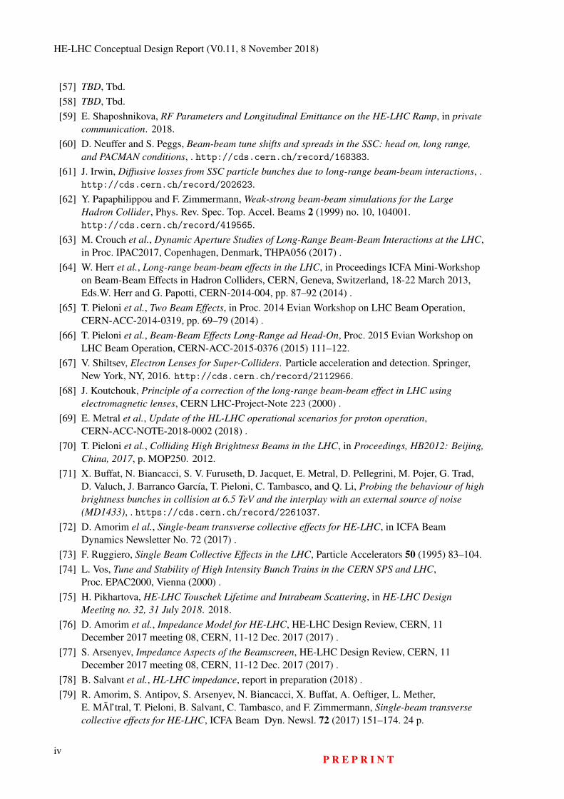
HE-LHC Conceptual Design Report (V0.11, 8 November 2018)
[57] TBD, Tbd.[58] TBD, Tbd.[59] E. Shaposhnikova, RF Parameters and Longitudinal Emittance on the HE-LHC Ramp, in private
communication. 2018.[60] D. Neuffer and S. Peggs, Beam-beam tune shifts and spreads in the SSC: head on, long range,
and PACMAN conditions, . http://cds.cern.ch/record/168383.[61] J. Irwin, Diffusive losses from SSC particle bunches due to long-range beam-beam interactions, .
http://cds.cern.ch/record/202623.[62] Y. Papaphilippou and F. Zimmermann, Weak-strong beam-beam simulations for the Large
Hadron Collider, Phys. Rev. Spec. Top. Accel. Beams 2 (1999) no. 10, 104001.http://cds.cern.ch/record/419565.
[63] M. Crouch et al., Dynamic Aperture Studies of Long-Range Beam-Beam Interactions at the LHC,in Proc. IPAC2017, Copenhagen, Denmark, THPA056 (2017) .
[64] W. Herr et al., Long-range beam-beam effects in the LHC, in Proceedings ICFA Mini-Workshopon Beam-Beam Effects in Hadron Colliders, CERN, Geneva, Switzerland, 18-22 March 2013,Eds.W. Herr and G. Papotti, CERN-2014-004, pp. 87–92 (2014) .
[65] T. Pieloni et al., Two Beam Effects, in Proc. 2014 Evian Workshop on LHC Beam Operation,CERN-ACC-2014-0319, pp. 69–79 (2014) .
[66] T. Pieloni et al., Beam-Beam Effects Long-Range ad Head-On, Proc. 2015 Evian Workshop onLHC Beam Operation, CERN-ACC-2015-0376 (2015) 111–122.
[67] V. Shiltsev, Electron Lenses for Super-Colliders. Particle acceleration and detection. Springer,New York, NY, 2016. http://cds.cern.ch/record/2112966.
[68] J. Koutchouk, Principle of a correction of the long-range beam-beam effect in LHC usingelectromagnetic lenses, CERN LHC-Project-Note 223 (2000) .
[69] E. Metral et al., Update of the HL-LHC operational scenarios for proton operation,CERN-ACC-NOTE-2018-0002 (2018) .
[70] T. Pieloni et al., Colliding High Brightness Beams in the LHC, in Proceedings, HB2012: Beijing,China, 2017, p. MOP250. 2012.
[71] X. Buffat, N. Biancacci, S. V. Furuseth, D. Jacquet, E. Metral, D. Pellegrini, M. Pojer, G. Trad,D. Valuch, J. Barranco García, T. Pieloni, C. Tambasco, and Q. Li, Probing the behaviour of highbrightness bunches in collision at 6.5 TeV and the interplay with an external source of noise(MD1433), . https://cds.cern.ch/record/2261037.
[72] D. Amorim el al., Single-beam transverse collective effects for HE-LHC, in ICFA BeamDynamics Newsletter No. 72 (2017) .
[73] F. Ruggiero, Single Beam Collective Effects in the LHC, Particle Accelerators 50 (1995) 83–104.[74] L. Vos, Tune and Stability of High Intensity Bunch Trains in the CERN SPS and LHC,
Proc. EPAC2000, Vienna (2000) .[75] H. Pikhartova, HE-LHC Touschek Lifetime and Intrabeam Scattering, in HE-LHC Design
Meeting no. 32, 31 July 2018. 2018.[76] D. Amorim et al., Impedance Model for HE-LHC, HE-LHC Design Review, CERN, 11
December 2017 meeting 08, CERN, 11-12 Dec. 2017 (2017) .[77] S. Arsenyev, Impedance Aspects of the Beamscreen, HE-LHC Design Review, CERN, 11
December 2017 meeting 08, CERN, 11-12 Dec. 2017 (2017) .[78] B. Salvant et al., HL-LHC impedance, report in preparation (2018) .[79] R. Amorim, S. Antipov, S. Arsenyev, N. Biancacci, X. Buffat, A. Oeftiger, L. Mether,
E. MÃl’tral, T. Pieloni, B. Salvant, C. Tambasco, and F. Zimmermann, Single-beam transversecollective effects for HE-LHC, ICFA Beam Dyn. Newsl. 72 (2017) 151–174. 24 p.
ivP R E P R I N T
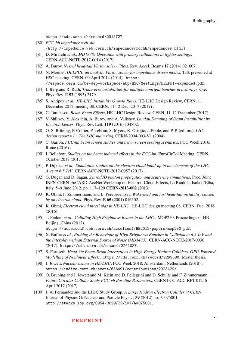
Bibliography
https://cds.cern.ch/record/2315727.[80] FCC-hh impedance web site,
http://impedance.web.cern.ch/impedance/fcchh/impedances.html.[81] D. Mirarchi et al., MD1878: Operation with primary collimators at tighter settings,
CERN-ACC-NOTE-2017-0014 (2017) .[82] A. Burov, Nested head-tail Vlasov solver, Phys. Rev. Accel. Beams 17 (2014) 021007.[83] N. Mounet, DELPHI: an analytic Vlasov solver for impedance-driven modes, Talk presented at
HSC meeting, CERN, 09 April 2014 (2014) . https://espace.cern.ch/be-dep-workspace/abp/HSC/Meetings/DELPHI-expanded.pdf.
[84] J. Berg and R. Ruth, Transverse instabilities for multiple nonrigid bunches in a storage ring,Phys. Rev. E 52 (1995) 2179.
[85] S. Antipov et al., HE-LHC Instability Growth Rates, HE-LHC Design Review, CERN, 11December 2017 meeting 08, CERN, 11-12 Dec. 2017 (2017) .
[86] C. Tambasco, Beam-Beam Effects, HE-LHC Design Review, CERN, 11-12 December (2017) .[87] V. Shiltsev, Y. Alexahin, A. Burov, and A. Valishev, Landau Damping of Beam Instabilities by
Electron Lenses, Phys. Rev. Lett. 119 (2016) 134802.[88] O. S. Brüning, P. Collier, P. Lebrun, S. Myers, R. Ostojic, J. Poole, and P. P. (editors), LHC
design report v.1 : The LHC main ring, CERN-2004-003-V1 (2004) .[89] C. Garion, FCC-hh beam screen studies and beam screen cooling scenarios, FCC Week 2016,
Rome (2016) .[90] I. Bellafont, Studies on the beam induced effects in the FCC-hh, EuroCirCol Meeting, CERN,
October 2017 (2017) .[91] P. Dijkstal et al., Simulation studies on the electron cloud build-up in the elements of the LHC
Arcs at 6.5 TeV , CERN-ACC-NOTE-2017-0057 (2017) .[92] G. Dugan and D. Sagan, Synrad3D photon propagation and scattering simulations, Proc. Joint
INFN-CERN-EuCARD-AccNet Workshop on Electron-Cloud Effects, La Biodola, Isola d’Elba,Italy, 5–9 June 2012, pp. 117–129 CERN-2013-002 (2013) .
[93] K. Ohmi, F. Zimmermann, and E. Perevedentsev, Wake-field and fast head-tail instability causedby an electron cloud, Phys. Rev. E 65 (2001) 016502.
[94] K. Ohmi, Electron cloud thresholds in HE-LHC, HE-LHC design meeting 08, CERN, Dec. 2016(2016) .
[95] T. Pieloni et al., Colliding High Brightness Beams in the LHC . MOP250. Proceedings of HBBeijing, China (2012).https://accelconf.web.cern.ch/accelconf/HB2012/papers/mop250.pdf.
[96] X. Buffat et al., Probing the Behaviour of High Brightness Bunches in Collision at 6.5 TeV andthe Interplay with an External Source of Noise (MD1433). CERN-ACC-NOTE-2017-0030(2017). https://cds.cern.ch/record/2261037.
[97] S. Furuseth, Head-On Beam-Beam Interactions in High-Energy Hadron Colliders. GPU-PoweredModelling of Nonlinear Effects. https://cds.cern.ch/record/2299580. Master thesis.
[98] J. Jowett, Nuclear beams in HE-LHC, FCC Week 2018, Amsterdam, Netherlands (2018) .https://indico.cern.ch/event/656491/contributions/2923429/.
[99] O. Brüning and J. Jowett and M. Klein and D. Pellegrini and D. Schulte and F. Zimmermann,Future Circular Collider Study FCC-eh Baseline Parameters, CERN FCC-ACC-RPT-012, 6April 2017 (2017) .
[100] J. A. Fernandez and the LHeC Study Group, A Large Hadron Electron Collider at CERN,Journal of Physics G: Nuclear and Particle Physics 39 (2012) no. 7, 075001.http://stacks.iop.org/0954-3899/39/i=7/a=075001.
P R E P R I N Tv
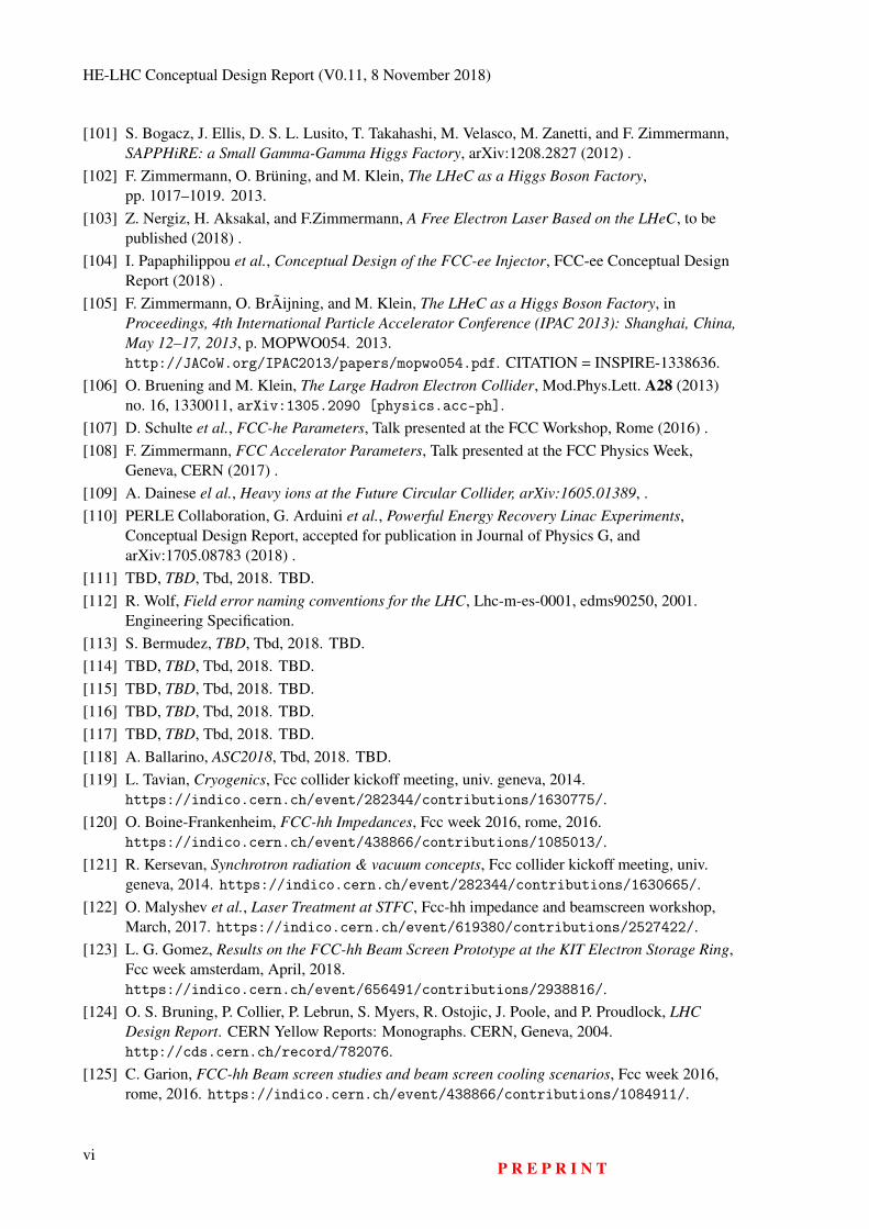
HE-LHC Conceptual Design Report (V0.11, 8 November 2018)
[101] S. Bogacz, J. Ellis, D. S. L. Lusito, T. Takahashi, M. Velasco, M. Zanetti, and F. Zimmermann,SAPPHiRE: a Small Gamma-Gamma Higgs Factory, arXiv:1208.2827 (2012) .
[102] F. Zimmermann, O. Brüning, and M. Klein, The LHeC as a Higgs Boson Factory,pp. 1017–1019. 2013.
[103] Z. Nergiz, H. Aksakal, and F.Zimmermann, A Free Electron Laser Based on the LHeC, to bepublished (2018) .
[104] I. Papaphilippou et al., Conceptual Design of the FCC-ee Injector, FCC-ee Conceptual DesignReport (2018) .
[105] F. Zimmermann, O. BrÃijning, and M. Klein, The LHeC as a Higgs Boson Factory, inProceedings, 4th International Particle Accelerator Conference (IPAC 2013): Shanghai, China,May 12–17, 2013, p. MOPWO054. 2013.http://JACoW.org/IPAC2013/papers/mopwo054.pdf. CITATION = INSPIRE-1338636.
[106] O. Bruening and M. Klein, The Large Hadron Electron Collider, Mod.Phys.Lett. A28 (2013)no. 16, 1330011, arXiv:1305.2090 [physics.acc-ph].
[107] D. Schulte et al., FCC-he Parameters, Talk presented at the FCC Workshop, Rome (2016) .[108] F. Zimmermann, FCC Accelerator Parameters, Talk presented at the FCC Physics Week,
Geneva, CERN (2017) .[109] A. Dainese el al., Heavy ions at the Future Circular Collider, arXiv:1605.01389, .[110] PERLE Collaboration, G. Arduini et al., Powerful Energy Recovery Linac Experiments,
Conceptual Design Report, accepted for publication in Journal of Physics G, andarXiv:1705.08783 (2018) .
[111] TBD, TBD, Tbd, 2018. TBD.[112] R. Wolf, Field error naming conventions for the LHC, Lhc-m-es-0001, edms90250, 2001.
Engineering Specification.[113] S. Bermudez, TBD, Tbd, 2018. TBD.[114] TBD, TBD, Tbd, 2018. TBD.[115] TBD, TBD, Tbd, 2018. TBD.[116] TBD, TBD, Tbd, 2018. TBD.[117] TBD, TBD, Tbd, 2018. TBD.[118] A. Ballarino, ASC2018, Tbd, 2018. TBD.[119] L. Tavian, Cryogenics, Fcc collider kickoff meeting, univ. geneva, 2014.
https://indico.cern.ch/event/282344/contributions/1630775/.[120] O. Boine-Frankenheim, FCC-hh Impedances, Fcc week 2016, rome, 2016.
https://indico.cern.ch/event/438866/contributions/1085013/.[121] R. Kersevan, Synchrotron radiation & vacuum concepts, Fcc collider kickoff meeting, univ.
geneva, 2014. https://indico.cern.ch/event/282344/contributions/1630665/.[122] O. Malyshev et al., Laser Treatment at STFC, Fcc-hh impedance and beamscreen workshop,
March, 2017. https://indico.cern.ch/event/619380/contributions/2527422/.[123] L. G. Gomez, Results on the FCC-hh Beam Screen Prototype at the KIT Electron Storage Ring,
Fcc week amsterdam, April, 2018.https://indico.cern.ch/event/656491/contributions/2938816/.
[124] O. S. Bruning, P. Collier, P. Lebrun, S. Myers, R. Ostojic, J. Poole, and P. Proudlock, LHCDesign Report. CERN Yellow Reports: Monographs. CERN, Geneva, 2004.http://cds.cern.ch/record/782076.
[125] C. Garion, FCC-hh Beam screen studies and beam screen cooling scenarios, Fcc week 2016,rome, 2016. https://indico.cern.ch/event/438866/contributions/1084911/.
viP R E P R I N T
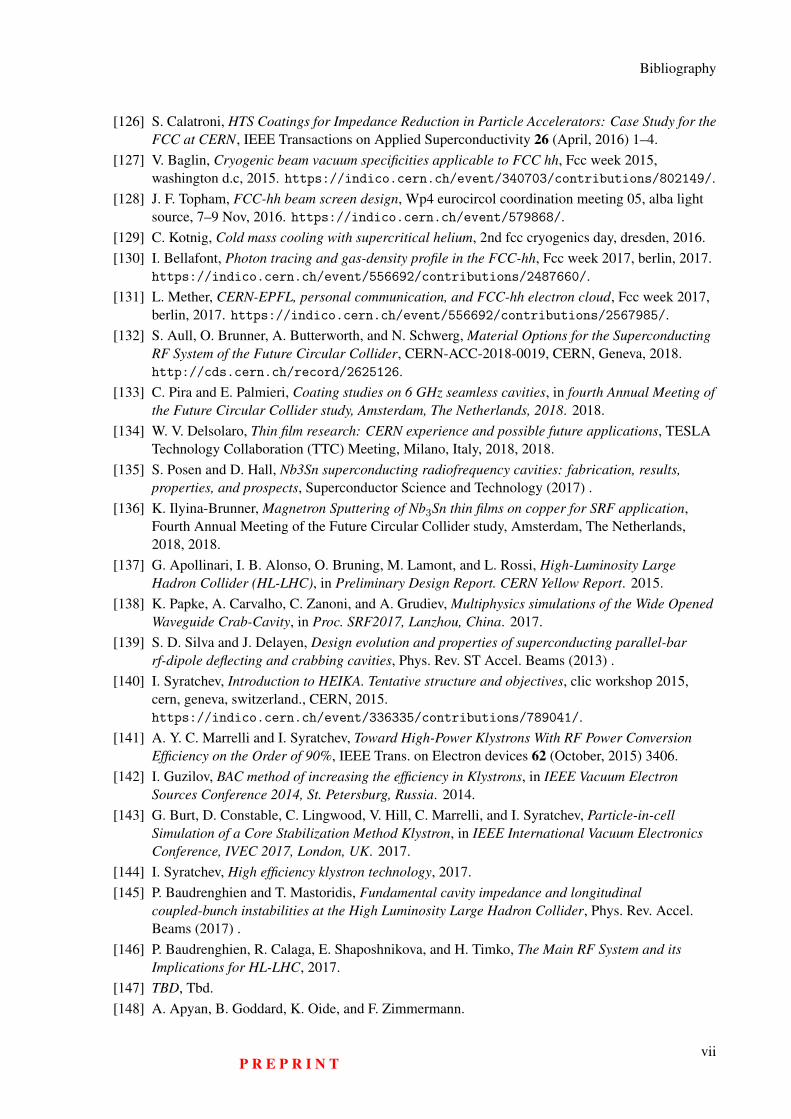
Bibliography
[126] S. Calatroni, HTS Coatings for Impedance Reduction in Particle Accelerators: Case Study for theFCC at CERN, IEEE Transactions on Applied Superconductivity 26 (April, 2016) 1–4.
[127] V. Baglin, Cryogenic beam vacuum specificities applicable to FCC hh, Fcc week 2015,washington d.c, 2015. https://indico.cern.ch/event/340703/contributions/802149/.
[128] J. F. Topham, FCC-hh beam screen design, Wp4 eurocircol coordination meeting 05, alba lightsource, 7–9 Nov, 2016. https://indico.cern.ch/event/579868/.
[129] C. Kotnig, Cold mass cooling with supercritical helium, 2nd fcc cryogenics day, dresden, 2016.[130] I. Bellafont, Photon tracing and gas-density profile in the FCC-hh, Fcc week 2017, berlin, 2017.
https://indico.cern.ch/event/556692/contributions/2487660/.[131] L. Mether, CERN-EPFL, personal communication, and FCC-hh electron cloud, Fcc week 2017,
berlin, 2017. https://indico.cern.ch/event/556692/contributions/2567985/.[132] S. Aull, O. Brunner, A. Butterworth, and N. Schwerg, Material Options for the Superconducting
RF System of the Future Circular Collider, CERN-ACC-2018-0019, CERN, Geneva, 2018.http://cds.cern.ch/record/2625126.
[133] C. Pira and E. Palmieri, Coating studies on 6 GHz seamless cavities, in fourth Annual Meeting ofthe Future Circular Collider study, Amsterdam, The Netherlands, 2018. 2018.
[134] W. V. Delsolaro, Thin film research: CERN experience and possible future applications, TESLATechnology Collaboration (TTC) Meeting, Milano, Italy, 2018, 2018.
[135] S. Posen and D. Hall, Nb3Sn superconducting radiofrequency cavities: fabrication, results,properties, and prospects, Superconductor Science and Technology (2017) .
[136] K. Ilyina-Brunner, Magnetron Sputtering of Nb3Sn thin films on copper for SRF application,Fourth Annual Meeting of the Future Circular Collider study, Amsterdam, The Netherlands,2018, 2018.
[137] G. Apollinari, I. B. Alonso, O. Bruning, M. Lamont, and L. Rossi, High-Luminosity LargeHadron Collider (HL-LHC), in Preliminary Design Report. CERN Yellow Report. 2015.
[138] K. Papke, A. Carvalho, C. Zanoni, and A. Grudiev, Multiphysics simulations of the Wide OpenedWaveguide Crab-Cavity, in Proc. SRF2017, Lanzhou, China. 2017.
[139] S. D. Silva and J. Delayen, Design evolution and properties of superconducting parallel-barrf-dipole deflecting and crabbing cavities, Phys. Rev. ST Accel. Beams (2013) .
[140] I. Syratchev, Introduction to HEIKA. Tentative structure and objectives, clic workshop 2015,cern, geneva, switzerland., CERN, 2015.https://indico.cern.ch/event/336335/contributions/789041/.
[141] A. Y. C. Marrelli and I. Syratchev, Toward High-Power Klystrons With RF Power ConversionEfficiency on the Order of 90%, IEEE Trans. on Electron devices 62 (October, 2015) 3406.
[142] I. Guzilov, BAC method of increasing the efficiency in Klystrons, in IEEE Vacuum ElectronSources Conference 2014, St. Petersburg, Russia. 2014.
[143] G. Burt, D. Constable, C. Lingwood, V. Hill, C. Marrelli, and I. Syratchev, Particle-in-cellSimulation of a Core Stabilization Method Klystron, in IEEE International Vacuum ElectronicsConference, IVEC 2017, London, UK. 2017.
[144] I. Syratchev, High efficiency klystron technology, 2017.[145] P. Baudrenghien and T. Mastoridis, Fundamental cavity impedance and longitudinal
coupled-bunch instabilities at the High Luminosity Large Hadron Collider, Phys. Rev. Accel.Beams (2017) .
[146] P. Baudrenghien, R. Calaga, E. Shaposhnikova, and H. Timko, The Main RF System and itsImplications for HL-LHC, 2017.
[147] TBD, Tbd.[148] A. Apyan, B. Goddard, K. Oide, and F. Zimmermann.
P R E P R I N Tvii
HE-LHC Conceptual Design Report (V0.11, 8 November 2018)
[149] O. Jones, First Years Experience of LHC Beam Instrumentation, Proc. IPAC2011, San Sebastian(2011) .
[150] CERN EDMS Specification, LHC-BPM-ES-0004 .https://edms.cern.ch/document/327557.
[151] M. Barros Marin et al., The Giga Bit Transceiver based Expandable Front-End (GEFE) - a newradiation tolerant acquisition system for beam instrumentation, JINST 11 C02062 (2016) .
[152] B. Dehning, E. Effinger, J. Emery, G. Ferioli, G. Guaglio, E. B. Holzer, D. Kramer, L. Ponce,V. Prieto, M. Stockner, and C. Zamantzas, The LHC beam loss measurement system, in 2007IEEE Particle Accelerator Conference (PAC), pp. 4192–4194. June, 2007.
[153] M. Fernandez et al., Optimized Cryogenic Current Comparator for CERN’s Low-EnergyAntiproton Facilities, IBIC2016, Barcelona, Spain (2016) .
[154] D. Belohrad et al., Upgrade of the LHC Bunch by Bunch Intensity Measurement AcquisitionSystem, IBIC2016, Barcelona, Spain (2016) .
[155] G. Trad et al., Performance of the Upgraded Synchrotron Radiation Diagnostics at the LHC,Proc. IPAC2016, Busan, Korea (2016) .
[156] H. Zhang et al., A Supersonic Gas-Jet Based Beam Induced Fluorescence Prototype Monitor forTransverse Profile Determination, Proc. IPAC2017, Copenhagen, Denmark (2017) .
[157] S. Vlachos et al., The LHC Beam Gas Vertex Detector - a Non-Invasive Profile Monitor for HighEnergy Machines, Proc. IBIC17, Grand Rapids, Michigan, USA (August, 2017) .
[158] D. Missiaen, J. Quesnel, and R. Steinhagen, The Alignment of the LHC, Proc. PAC2009Vancouver, Canada (2009) .
[159] Y. Nie, R. Schmidt, V. Chetvertkova, G. Rosell-Tarragó, F. Burkart, and D. Wollmann, Numericalsimulations of energy deposition caused by 50 MeV–50 TeV proton beams in copper and graphitetargets, Phys. Rev. Accel. Beams 20 (August, 2017) 081001.https://link.aps.org/doi/10.1103/PhysRevAccelBeams.20.081001.
[160] M. Werner and K. Wittenburg, Very fast beam losses at HERA, and what has been done about it,Technical report, desy, 2006, 2006.
[161] Q. Bai, B. Jin, D. Wang, Y. Wang, and X. Liu, Compact Modbus TCP/IP protocol for dataacquisition systems based on limited hardware resources, Journal of Instrumentation 13 (2018)no. 04, T04004. http://stacks.iop.org/1748-0221/13/i=04/a=T04004.
[162] T. Wilksen et al., The Control System for the Linear Accelerator at the European XFEL: Statusand First Experiences, in Proceedings, 16th International Conference on Accelerator and LargeExperimental Physics Control Systems (ICALEPCS 2017): Barcelona, Spain, October 8–13,2017, p. MOAPL01. 2018.http://inspirehep.net/record/1656098/files/moapl01.pdf.
[163] R. Ganter et al., SwissFEL Conceptual Design Report, PSI Bericht 10–14, Paul Scherrer Institut,July, 2010.https://www.psi.ch/swissfel/SwissFELCDREN/SwissFEL_CDR_web_small.pdf.
[164] R. Huhmann et al., The FAIR Control System - System Architecture and First Implementations, inProceedings of ICALEPCS2013, San Francisco, CA, USA, p. MOPPC097. 2013.http://accelconf.web.cern.ch/AccelConf/ICALEPCS2013/papers/moppc097.pdf.
[165] M. Hankel and B. Rexroth, The Reference Architectural Model Industrie 4.0 (RAMI 4.0),Whitepaper Version 1.0, ZVEI: Die Elektroindustrie, April, 2015.https://www.zvei.org/fileadmin/user_upload/Themen/Industrie_4.0/Das_Referenzarchitekturmodell_RAMI_4.0_und_die_Industrie_4.0-Komponente/pdf/ZVEI-Industrie-40-RAMI-40-English.pdf.
[166] E. Boven, White Rabbit in Radio Astronomy, in Proceedings of ICALEPCS2017, Barcelona,
viiiP R E P R I N T
Bibliography
Spain, p. TUCPL03. 2017. http://accelconf.web.cern.ch/AccelConf/icalepcs2017/.[167] N. Moreira et al., On the Utilization of System-on-Chip Platforms to Achieve Nanosecond
Synchronization Accuracies in Substation Automation Systems, IEEE Transactions on Smart Grid8 (July, 2017) 1932–1942. DOI 10.1109/TSG.2015.2512440.
[168] P. Loschmidt, R. Excel, and G. Gaderer, Highly accurate timestamping for Ethernet-based clocksynchronization, Comput. Netw. Commun. 2012 (2012) 1–11.http://dx.doi.org/10.1155/2012/152071.
[169] As-2d2 Deterministic Ethernet And Unified Networking, Time-Triggered Ethernet, Standard AS6802, SAE International, September, 2016. https://doi.org/10.4271/AS6802.
[170] J. Allnut et al., Timing Challenges in the Smart Grid, Natl. Inst. Stand. Technol. Spec. Publ.1500-08, U.S. Department of Commerce, January, 2017.https://doi.org/10.6028/NIST.SP.1500-08.
[171] C. Sydlo et al., Femtosecond Timing Distribution at the European XFEL, in Proceedings ofFEL2015, Daejeon, Korea, p. WEP047. 2015.http://accelconf.web.cern.ch/AccelConf/FEL2015/papers/wep047.pdf.
[172] A. Aghababyan et al., The Large Scale European XFEL Control System: Overview and Status ofthe Commissioning, in Proceedings of ICALEPCS2015, Melbourne, Australia, p. MOA3O02.2015. http://tesla.desy.de/doocs/doocs_papers/ICALEPCS2015/moa3o02.pdf.
[173] B. Todd, A. Dinius, Q. King, and S. Uznanski, Radiation tolerant power converter controls,Journal of Instrumentation 7 (2012) no. 11, C11012.http://stacks.iop.org/1748-0221/7/i=11/a=C11012.
[174] F. Abdi et al., Application and System-Level Software Fault Tolerance through Full SystemRestarts, in ACM/IEEE 8th International Conference on Cyber-Physical Systems (ICCPS),Pittsburgh, PA, USA, pp. 6505–6519. April, 2017.https://ieeexplore.ieee.org/document/7945009/.
[175] W. Benjamin et al., An open architecture for embedded systems: Hardware Open SystemsTechnologies, in IEEE SoutheastCon, Charlotte, NC, USA, pp. 6505–6519. 2017.https://doi.org/10.1109/SECON.2017.7925388.
[176] P. Bieth and V. Brindejonc, COTS-AEH - Use of complex COTS in airborne electronic hardware -failure mode and mitigation, Research Project EASA.2012.C15 Report EASA.2012/04,European Aviation Safety Agency, 2013. https://www.easa.europa.eu/sites/default/files/dfu/Final%20Report%20EASA%202012-04.pdf.
[177] National Instruments, Considerations When Navigating Build or Buy Decisions for IndustrialEmbedded Control Projects, White Paper 54072, National Instruments, August, 2017.http://www.ni.com/white-paper/54072/en/.
[178] L. Yucheng and L. Yubin, High Continuous Availability Digital Information System Based onStratus Fault-Tolerant Server, in 2010 International Forum on Information Technology andApplications, vol. 2, pp. 184–187. July, 2010. DOI: 10.1109/IFITA.2010.79.
[179] B. Chen et al., Smart Factory of Industry 4.0: Key Technologies, Application Case, andChallenges, IEEE Access 6 (2017) 6505–6519. DOI: 10.1109/ACCESS.2017.2783682.
[180] A. Voto, I. Dai, P. Oleniuk, and B. Todd, Standardization of automated industrial test equipmentfor mass production of control systems, Journal of Instrumentation 11 (2016) no. 01, C01047.http://stacks.iop.org/1748-0221/11/i=01/a=C01047.
[181] IEEE, Systems and software engineering - System lifecycle processes, Standard ISO 15288:2008,IEEE/ISO/IEC, 2008. https://en.wikipedia.org/wiki/ISO/IEC_15288.
[182] K. Forsberg and H. Mooz, System Engineering for Faster, Cheaper, Better, in INCOSEInternational Symposium Systems Engineering Past, Present and Future I, Brighton, England,vol. 9, pp. 924–932. June, 1999.
P R E P R I N Tix

HE-LHC Conceptual Design Report (V0.11, 8 November 2018)
https://doi.org/10.1002/j.2334-5837.1999.tb00258.x.[183] European Commission, Horizon 2020 Work Programme 2016 - 2017. 5.i. Information and
Communication Technologies, European Commission Decision C(2017)2468, EuropeanCommission, April, 2017. http://ec.europa.eu/research/participants/data/ref/h2020/wp/2016_2017/main/h2020-wp1617-leit-ict_en.pdf.
[184] J. Gutleber et al., The MedAustron accelerator control system, in Proceedings ofICALEPCS2011, Grenoble, France, no. MOBAUST03, pp. 9–12. October, 2011.https://accelconf.web.cern.ch/accelconf/icalepcs2011/papers/mobaust03.pdf.
[185] J. Gutleber and R. Moser, The MedAustron Accelerator Control System: Design Installation andCommissioning, in 14th International Conference on Accelerator and Large ExperimentalPhysics Control Systems, San Francisco, CA, USA. March, 2013.https://cds.cern.ch/record/1697002.
[186] Cosylab, Accelerator Control System for PT , Website, 2018.https://www.cosylab.com/accelerator-control-system-for-pt/.
[187] D. Ondreka and U. Weinrich, The Heidelberg Ion Therapy (HIT) Accelerator Coming intoOperation, in European Physical Society Accelerator Group, Proceedings of EPAC 2008, Genoa,Italy, no. TUOCG01, pp. 979–981. June, 2008.https://accelconf.web.cern.ch/accelconf/e08/papers/tuocg01.pdf.
[188] S. Rossi et al., The Status of CNAO, S. Eur. Phys. J. Plus 126 (August, 2011) .https://doi.org/10.1140/epjp/i2011-11078-8.
[189] S. Giordanengo et al., The CNAO dose delivery system for modulated scanning ion beamradiotherapy, Medical Physics 42 (November, 2016) 263–275.https://doi.org/10.1118/1.4903276.
[190] L. Evans and P. Bryant (editors), The CERN Large Hadron Collider: Accelerator andExperiments, Control System, Journal of Instrumentation 3 (2008) no. 08, S08001, pp.98.http://stacks.iop.org/1748-0221/3/i=08/a=S08001.
[191] B. Kihei, Automotive Doppler sensing: The Doppler profile with machine learning invehicle-to-vehicle networks for road safety, in 18th IEEE International Workshop on SignalProcessing Advances in Wireless Communications, Sapporo, Japan. July, 2017. DOI10.1109/SPAWC.2017.8227637.
[192] ICFA, Beam Dynamics Mini-Workshop: Machine Learning Applications for ParticleAccelerators. SLAC National Accelerator Laboratory, Menlo Park, CA, USA., Website,27 February–2 March, 2018.https://indico.fnal.gov/event/16327/other-view?view=standard.
[193] R. Alia et al., Single event effects in high energy accelerators, Semiconductor Science andTechnology (2017) . http://iopscience.iop.org/10.1088/1361-6641/aa5695.
[194] T. T. Böhlen, F. Cerutti, M. P. W. Chin, A. Fassò, A. Ferrari, P. G. Ortega, A. Mairani, P. R. Sala,G. Smirnov, and V. Vlachoudis, The FLUKA Code: Developments and Challenges for HighEnergy and Medical Applications, Nuclear Data Sheets 120 (June, 2014) 211–214.http://adsabs.harvard.edu/abs/2014NDS...120..211B.
[195] A. Ferrari, P. Sala, A. Fassò, and J. Ranft, FLUKA: a multi-particle transport code, ReportCERN-2005-10, CERN, Geneva, Switzerland, 2005. Also available as INFN/TC_05/11 andSLAC-R-773.
[196] R. Alia et al., LHC and HL-LHC: Present and Future Radiation Environment in theHigh-Luminosity Collision Points and RHA Implication, IEEE Transactions on Nuclear Science65 (Jan, 2018) 448–456.
[197] B. Gkotse, M. Brugger, P. Carbonez, S. Danzeca, A. Fabich, R. Garcia, Alia, M. Glaser,G. Gorine, R. Jaekel, Martin, I. Mateu, Suau, G. Pezzullo, F. Pozzi, F. Ravotti, M. Silari, and
xP R E P R I N T
Bibliography
M. Tali, Irradiation Facilities at CERN, . https://cds.cern.ch/record/2290629.[198] F. Pozzi, P. Carbonez, and R. Macián-Juan, CERN Radiation Protection (RP) calibration
facilities. PhD thesis, September, 2015. https://cds.cern.ch/record/2256137. Presented01 Jul 2016.
[199] M. Jäkel et al., CERN GIF++: A new irradiation facility to test large- area particle detectors forthe high-luminosity LHC program, PoS (TIPP2014):102 in Proc. Technology and Instrumentationin Particle Physics, Amsterdam (2014) . https://pos.sissa.it/213/102/pdf.
[200] G. Tsiligiannis, S. Danzeca, R. Garcia-Alia, A. Infantino, A. Lesea, M. Brugger, A. Masi,S. Gilardoni, and F. Saigné, Radiation Effects on Deep Sub-micron SRAM-based FPGAs underthe CERN Mixed-Field Radiation Environment, IEEE Transactions on Nuclear Science PP(2018) no. 99, 1–1.
[201] M. Zhang, F. Jazaeri, A. Pezzotta, C. Bruschini, G. Borghello, F. Faccio, S. Mattiazzo,A. Baschirotto, and C. Enz, GigaRad total ionizing dose and post-irradiation eïnAects on 28 nmbulk MOSFETs, in Proceedings 2016 IEEE Nuclear Science Symposium, Medical ImagingConference and Room-Temperature Semiconductor Detector Workshop (NSS/MIC/RTSD),pp. 1–4. October, 2016.
[202] G. Gorine, G. Pezzullo, I. Mandic, A. Jazbec, L. Snoj, M. Capeans, M. Moll, D. Bouvet,F. Ravotti, and J. Sallese, Ultra High Fluence Radiation Monitoring Technology for the FutureCircular Collider at CERN, IEEE Transactions on Nuclear Science 65 (January, 2018)1583–1590.
[203] H. Rammer, Two new caverns for LHC experiments: ATLAS and CMS, , CERN, Chamonix,February, 1998. https://cds.cern.ch/record/357157/files/st-98-005.pdf. 1st STWorkshop.
[204] C. Laughton, Grouting and support techniques used in the Karstic Limestones of the Juramountains for the LEP underground laboratory, Int J Min Geol Eng (International Journal ofMining and Geological Engineering) 6 (1988) 353–365.
[205] J. Baldy, Commission Tunnel Jura, EDMS 2041211, CERN, Geneva, June, 1999.[206] J. Baldy, Tunnel LEP Secteur Jura Etudes du renforcement local du revetement en beton, EDMS
2041211, restricted access., CERN, Geneva, June, 1999.[207] J. Dale, A. Reichold, A. Lancaster, P. Brockill, B. Hughes, A. Lewis, M. Warden, and
H. Schwenke, A Novel Multichannel Interferometer System For Absolute DistanceMeasurements, Large Volume Metrology Conference (2012) .
[208] D. Clark, PathForward gets down to work [computer project], IEEE Computational Science andEngineering 5 (Jan, 1998) 84–85. https://doi.org/10.1109/99.660319.
[209] I. Bird, L. Robertson, and J. Shiers, Deploying the LHC computing grid - the LCG servicechallenges, in 2005 IEEE International Symposium on Mass Storage Systems and Technology,pp. 160–165. June, 2005. https://doi.org/10.1109/LGDI.2005.1612486.
[210] J. Webber, The ALMA Telescope, in 2013 IEEE MTT-S International Microwave SymposiumDigest (MTT), pp. 1–3. June, 2013. https://doi.org/10.1109/MWSYM.2013.6697433.
[211] D. Ding, D. Wu, and F. Yu, An overview on cloud computing platform spark for Human Genomemining, in 2016 IEEE International Conference on Mechatronics and Automation. August,2016. 2605--2610. https://doi.org/10.1109/ICMA.2016.7558977.
[212] G. Antchev, E. Cano, S. Chatelier, S. Cittolin, S. Erhan, D. Gigi, J. Gutleber, C. Jacobs,F. Meijers, L. Orsini, L. Pollet, A. Racz, D. Samyn, N. Sinanis, and P. Sphicas, The CMS eventbuilder demonstrator based on Myrinet, IEEE Transactions on Nuclear Science 47 (April, 2000)293–298. https://doi.org/10.1109/23.846167.
[213] K. Anikeev, G. Bauer, I. Furic, D. Holmgren, A. Korn, I. Kravchenko, M. Mulhearn, P. Ngan,C. Paus, A. Rakitin, R. Rechenmacher, T. Shah, P. Sphicas, K. Sumorok, S. Tether, J. Tseng, and
P R E P R I N Txi
HE-LHC Conceptual Design Report (V0.11, 8 November 2018)
F. Wüerthwein, Event Builder and Level 3 trigger at the CDF experiment, Computer PhysicsCommunications 140 (2001) no. 1, 110–116.http://www.sciencedirect.com/science/article/pii/S0010465501002612.CHEP2000.
[214] DESY, MicroTCA Technology Lab, Website, 2018. https://techlab.desy.de.[215] CERN, openlab, Website, 2018. https://openlab.cern.[216] Conseil régional Auvergne-Rhône-Alpes, Numérique. Feuille de route stratégique de la Région
Auvergne-Rhône-Alpes 2017-2021, Website of the ara region, 2018. https://www.auvergnerhonealpes.fr/95-infrastructures-economie-usages-numeriques.htm.
[217] Grand Genève Agglomération Franco-Valdo-Genevoise, Charte d’engagement du projet deterritoire Grand Geneève 2016-2030, December, 2016.http://www.grand-geneve.org/sites/default/files/fichiers/projet-agglomeration3/charte_2016-projet-territoire.pdf.
[218] Sepura, Case study: Advancing safety and communications at CERN, January, 2014.https://www.sepura.com/media/166841/cern-case-study.pdf.
[219] Euro-IX, Information on carrier neutrality, Website, 2018.https://www.euro-ix.net/en/forixps/set-ixp/ixp-models/neutrality.
[220] CERN, Documents and maps of the Worldwide LHC Computing Grid (WLCG), Website, 2018.http://wlcg.web.cern.ch/documents-reference.
[221] H. Schopper, The light of SESAME: A dream becomes reality, Rivista del Nuovo Cimento 40(2017) no. 4, 199–239.https://www.sif.it/riviste/sif/ncr/econtents/2017/040/04/article/0.
[222] B. Panzer-Steindel, IT Technology and Markets, Status and Evolution, March, 2018.https://indico.cern.ch/event/658060/contributions/2889027/attachments/1622791/2583013/tech_market_BPS_Mar2018_v9pptx.pdf.
[223] A. D. Meglio, M. Girone, A. Purcell, and F. Rademakers, CERN openlab white paper on futureICT challenges in scientific research, , January, 2018.http://cds.cern.ch/record/2301895.
[224] A. Bastianin and M. .Florio, Social Cost Benefit Analysis of HL-LHC, CERN-ACC-2018-0014,CERN, Geneva, May, 2018. https://cds.cern.ch/record/2319300.
[225] S. Schmeling, Common tools for large experiment controls-a common approach for deployment,maintenance, and support, IEEE Transactions on Nuclear Science 53 (June, 2006) 970–973.https://doi.org/10.1109/TNS.2006.873706.
[226] D. Collaboration, Data Preservation in High Energy Physics (DPHEP), Website, 2018.https://hep-project-dphep-portal.web.cern.ch.
[227] J. Shiers, F. Berghaus, J. Blomer, G. Ganis, S. Dallmeier-Tiessen, T. Simko, andG. Cancio-Melia, CERN Services for Long Term Data Preservation, CERN-IT-Note-2016-004,CERN, Geneva, July, 2016. https://cds.cern.ch/record/2195937.
[228] G. de Rijk (Chair), Workshop on a Low Energy Ring in the LHC tunnel as Main Injector, .http://ler06.web.cern.ch/LER06.
[229] F. Burkart, W. Bartmann, M. Benedikt, B. Goddard, A. Milanese, and J. Schmidt, ConceptualDesign Considerations for a 1.3 TeV Superconducting SPS (scSPS), in Proceedings, 8thInternational Particle Accelerator Conference (IPAC 2017): Copenhagen, Denmark, May 14–19,2017, p. WEPVA033. 2017.http://inspirehep.net/record/1626398/files/wepva033.pdf.
[230] B. Goddard et al., Chapter 5: Physics Opportunities with the FCC-hh Injectors, CERN YellowReports: Monographs 3 (2017) no. 0, 693.
xiiP R E P R I N T
Bibliography
https://e-publishing.cern.ch/index.php/CYRM/article/view/516.[231] D. Barna, High field septum magnet using a superconducting shield for the Future Circular
Collider, Phys. Rev. Accel. Beams 20 (Apr, 2017) 041002.https://link.aps.org/doi/10.1103/PhysRevAccelBeams.20.041002.
[232] A. Kovalenko, W. Scandale, and A. Taratin, Bent crystal extraction from a 100TeV protoncollider, Nuclear Instruments and Methods in Physics Research Section B: Beam Interactionswith Materials and Atoms 355 (2015) 390–394.http://www.sciencedirect.com/science/article/pii/S0168583X15000567.
[233] I. Efthymiopoulos, C. Hessler, H. Gaillard, D. Grenier, M. Meddahi, P. Trilhe, A. Pardons,C. Theis, N. Charitonidis, S. Evrard, H. Vincke, and M. Lazzaroni, HiRadMat: A NewIrradiation Facility for Material Testing at CERN, . http://cds.cern.ch/record/1403043.
[234] Gouvernment de la République française and CERN, Accord entre le Gouvernement de laRépublique française et l’Organisation Européenne pour la Recherche Nucléaire relatif au statutjuridique de ladite Organisation en France. CERN institutional documents. CERN, Geneva,August, 1973. https://cds.cern.ch/record/436804/files/CM-B00042459.pdf.
[235] U. Forsblom-Pärli et al., Connaissez-vous le potentiel des phénomènes dangereux dans votreentreprise?, instruction, système selon commission fédérale de coordination pour la sécurité autravail, SUVA - Protection de la santé, June, 2011.https://www.suva.ch/materiel/documentation/connaissezvous-le-potentiel-des-phenomenes-dangereux-dans-votre-entreprise--le--66105.f-25527-25526.
[236] S. L. Mendola, FCC performance-based safety design - A proposal for a methodology foundedon the SFPE guideline, internal presentation, CERN, June, 2017.https://edms.cern.ch/document/1770088.
[237] International Electrotechnical Commission, IEC 60812:2018 - Failure modes and effects analysis(FMEA and FMECA). International Standard. IEC, Geneva, 3.0 ed., August, 2018.https://cds.cern.ch/record/436804/files/CM-B00042459.pdf.
[238] O. R. Rubiras, HE-LHC Quantitative Fire Hazard Assessment, EDMS 1975608, CERN, Geneva,2018. https://edms.cern.ch/document/1975608/.
[239] A. Henriques, Private communication, , CERN, Geneva, April, 2018.[240] O. R. Rubiras, FCC-hh Fire Hazard Executive Summary, EDMS 1975608, CERN, Geneva, 2018.
https://edms.cern.ch/document/1982356/.[241] K. McGrattan et al., Fire Dynamics Simulator User’s Guide, special publication, National
Institute of Standards and Technology, June, 2018.https://pages.nist.gov/fds-smv/;https://github.com/firemodels/fds/releases/download/FDS6.7.0/FDS_User_Guide.pdf.
[242] B. S. Institute, The application of fire safety engineering principles to fire safety design ofbuildings: part 6 : Human factors: Life safety strategies : occupant evacuation, behaviour andcondition (sub-system 6). British Standards Institute, London, 2004. PD 7974-6.
[243] T. Otto, Release of Gaseous Helium in Tunnels, EDMS 1853419, CERN, Geneva, October, 2017.https://edms.cern.ch/document/1853419.
[244] L. Bruno and M. Magistris, Radioactive Waste Management at CERN, EDMS 1453489, CERN,Geneva, June, 2017. https://cds.cern.ch/record/1453489.
[245] Energy for Sustainable Science at Research Infrastructures, 4th workshop inmagurele-bucharest/romania, November, 2017.
[246] EuCard2 (Enhanced European Coordination for Accelerator Research and Development),Project website. http://eucard2.web.cern.ch/.
P R E P R I N Txiii
HE-LHC Conceptual Design Report (V0.11, 8 November 2018)
[247] EuCard2 Work Package 3, Project website. https://www.psi.ch/enefficient/.[248] ARIES (Accelerator Research and Innovation for European Science and Society), Project
website. https://aries.web.cern.ch/.[249] TBD, Tbd.[250] A. Grosjean, Tout un quartier chauffé grâce au CERN, Tribune de Genève (February, 2018) .
https://www.tdg.ch/geneve/actu-genevoise/Tout-un-quartier-chauffe-grce-au-CERN/story/28974479.
[251] R. de Boer, S. Smeding, and K. Biesheuvel, Waste Heat recovery in industrial batch processes:analysis of combines heat storage and heat pump application, in Proc. 12th IEA Heat PumpConference, no. 12 in HPC, IEA. Rotterdam, The Netherlands, June, 2017.http://hpc2017.org/wp-content/uploads/2017/05/O.3.8.1-Waste-Heat-recovery-in-industrial-batch-processes-analysis-of-combined-heat-storage.pdf.
[252] F. Campana et al., ORC waste heat recovery in European energy intensive industries: Energyand GHG savings, Energ. Convers. Manage. 76 (December, 2013) 244–252.https://doi.org/10.1016/j.enconman.2013.07.041.
[253] P. Colonna et al., Organic Rankine Cycle Power Systems: From the Concept to CurrentTechnology, Applications, and an Outlook to the Future, Journal of Engineering for Gas Turbinesand Power 137 (March, 2015) . http://dx.doi.org/10.1115/1.4029884.
[254] Accord entre le Gouvernement de la République française et l’Organisation européenne pour laRecherche nucléaire relatif au statut juridique de ladite Organisation en France. CERN, Geneva,Switzerland, 1973. https://cds.cern.ch/record/436804.
[255] Convention entre le Conseil fédéral de la Confédération suisse et le Gouvernement de laRépublique française relative Ãa l’extension en territoire français du domaine de l’Organisationeuropéenne pour la recherche nucléaire. Le Conseil fédéral, Chancellerie fédérale, Palais fédéralouest, 3003 Berne, Switzerland, September, 1965.https://www.admin.ch/opc/fr/classified-compilation/19650161.
[256] M. Zahnd and A. Poiron, FCC Layout Review in Switzerland, deliverable report contract ca3797383, Ecotec, December, 2017. https://edms.cern.ch/document/1838912.
[257] Le Conseil fédéral suisse, Ordonnance relative à l’étude de l’impact sur l’environnement814.011 (UVPV), Recueil officiel du droit fédéral (RO) (OCtober, 2016) .https://www.admin.ch/opc/fr/classified-compilation/19880226/index.html.
[258] Office fédéral de l’environnement OFEV, Directive de la Confédération sur l’étude de l’impactsur l’environnement (Manuel EIE), Serie L’environnement pratique (2009) . https://www.bafu.admin.ch/bafu/fr/home/themes/eie/publications/manuel-eie.html.
[259] Le Président de la République, Code de l’environnement, Journal officiel de la Républiquefrançaise (September, 2018) . https://www.legifrance.gouv.fr/affichCode.do?cidTexte=LEGITEXT000006074220&dateTexte=20180924.
[260] UNECE, Convention on environmental impact assessment in a transboundary context,Convention ECE/MP.EIA/21/Amend.1, United Nations, Avenue de la Paix 8, 1202 Genève,Suisse, October, 2017. http://www.unece.org/env/eia/about/eia_text.html.
[261] Office Fédéral de la santé publique, Radioactivité de l’environnement et doses de rayonnementsen Suisse, Rapport 2017, Project website, 2018. http://www.bag.admin.ch/ura-jb.
[262] R. Rata and M. Widorski, Radiological studies for the FCC-hh arc sections, Edms 1905211,2018.
[263] R. Rata and M. Widorski, Radiological studies for the FCC-hh collimation regions, Edms1975526, 2018.
xivP R E P R I N T
Bibliography
[264] R. Rata and M. Widorski, Radiological studies for the FCC-hh experimental caverns, Edms1976620, 2018.
[265] D. Chanal and A. Bibet-Chevalier, Étude de sensibilité du scenario d’implantation du projectFCC en France et de ses opportunités, Rapport d’étude du Cerema FCC-INF-RPT-040 andEDMS 1853668, CEREMA, April, 2018. https://edms.cern.ch/document/1853668.
[266] Le Conseil fédéral suisse, Ordonnance sur l’aménagement du territoire (OAT) 700.1, Recueilofficiel du droit fédéral (RO) (January, 2016) .https://www.admin.ch/opc/fr/classified-compilation/national.html.
[267] GeniLac, http://www.citedelenergie.ch/fileadmin/user_upload/Energiestadt/de/Dateien/Instrumente/6_Kommunikation/6_5_2_GeniLa.pdf.
[268] L. Bruno and M. Magistris, Process of radioactive waste management, EDMS 1453489, CERN,Geneva, June, 2017. https://cds.cern.ch/record/1453489.
[269] M. Magistris, Radioactive Waste estimates for the FCC project, EDMS 1992036, CERN,Geneva, 2018. https://cds.cern.ch/record/1992036.
[270] Départment du Rhône-Métropole de Lyon, Plan de prévention et de gestion des déchets nondangereux du Rhône et de la Métropole de Lyon, version définitive, Départment duRhône-Métropole de Lyon, June, 2015. http://www.sindra.org/wp-content/uploads/2017/01/Plan-d\’echets-non-dangereux-Rh\h^one-M\’etropole-de-Lyon.pdf.
[271] Le Président de la République, Loi n. 2015-992 du 17 août 2015 relative à la transitionénergétique pour la croissance verte, Journal officiel de la République française (February, 2018)14263. https://www.legifrance.gouv.fr/affichTexte.do?cidTexte=JORFTEXT000031044385.
[272] République et Canton de Genève, Genève - Plan directeur cantonal 2030, permière mise à jour,Direction de la planification directrice cantonale et régionale, service du plan directeur cantonal,February, 2017. https://www.ge.ch/consulter-plans-amenagement-adoptes/plan-directeur-cantonal.
[273] P. Joxe, LOI d’orientation n. 92-125 du 6 février 1992 relative à l’administration territoriale dela République, Journal officiel de la République française 33 (February, 2018) 2064.https://www.legifrance.gouv.fr/affichTexte.do?cidTexte=JORFTEXT000000722113&dateTexte=20180201.
[274] Le Président de la République, LOI constitutionnelle n 2003-276 du 28 mars 2003 relative àl’organisation décentralisée de la République, Journal officiel de la République française 75(March, 2003) 5568. https://www.legifrance.gouv.fr/affichTexte.do?cidTexte=JORFTEXT000000722113&dateTexte=20180201.
[275] UNECE, Convention on Access to Information, Public Participation in Decision-Making andAccess to Justice in Environmental Matters, Treaty Series 2161 (June, 1998) 447.https://treaties.un.org/Pages/src-IND-mtdsg_no-XXVII~13-chapter-27-lang-_en-PageView.aspx.
[276] CEREMA, Rapport d’études sur les impacts pour l’État en matière de procédures etd’engagements financiers, report, Secrétariat Gégnéral pour les Affaires Régionalesd’Auvergne-Rhône-Alpes, April, 2018. This report is for government-internal purposes only.
[277] Le Président de la République, JORF n. 248 du 23 octobre 2002 page 17545 texte n. 20. Décretn. 2002-1275 du 22 octobre 2002 relatif à l’organisation du débat public et a la Commissionnationale du débat public, Journal officiel de la République française (JORF) (October, 2002) .https://www.legifrance.gouv.fr/affichTexte.do?cidTexte=JORFTEXT000000232649&categorieLien=id.
[278] Le Président de la République, Ordonnance n. 2016-1058 du 3 août 2016 relative à lamodification des règles applicables à l’évaluation environnementale des projets, plans et
P R E P R I N Txv
HE-LHC Conceptual Design Report (V0.11, 8 November 2018)
programmes, Journal officiel de la République française (JORF) (August, 2016) .https://www.legifrance.gouv.fr/affichTexte.do?cidTexte=JORFTEXT000032966723&categorieLien=id.
[279] Commission nationale du débat public, Comment ça marche ?, site internet de l’institution,Commission nationale du débat public, 244 boulevard Saint-Germain 75007 Paris France,October, 2002. https://www.debatpublic.fr/comment-ca-marche.
[280] Journal officiel de la République française (JORF), JORF n. 0261 du 11 novembre 2014 page19003 texte n. 7 Ordonnance n. 2014-1345 du 6 novembre 2014 relative à la partie législative ducode de l’expropriation pour cause d’utilité publique, Journal officiel de la République française(November, 2014) . https://www.legifrance.gouv.fr/affichTexte.do;jsessionid=62A9EC171A12674F234586C187CE51F1.tplgfr24s_3?cidTexte=JORFTEXT000029730657&dateTexte=20141111.
[281] Le Président de la République, Ordonnance n. 2017-80 du 26 janvier 2017 relative àl’autorisation environnementale, Journal officiel de la République française (August, 2018) .https://www.legifrance.gouv.fr/affichTexte.do?cidTexte=JORFTEXT000033926976.
[282] Le Président de la République, LOI n. 2010-597 du 3 juin 2010 relative au Grand Paris, Journalofficiel de la République française 0128 (August, 2018) 10339. https://www.legifrance.gouv.fr/affichTexte.do?cidTexte=JORFTEXT000022308227.
[283] Direction de l’ARE, Surfaces d’assolement selon le plan sectoriel SA, Modèle de géodonnéesminimal. Documentation sur le modèle. 68, Office fédéral du développement territorial ARE,Worblenstrasse 66, CH-3063 Ittingen, Schweiz, November, 2015. https://www.are.admin.ch/are/fr/home/developpement-et-amenagement-du-territoire/strategie-et-planification/conceptions-et-plans-sectoriels/plans-sectoriels-de-la-confederation/sda.html.
[284] Conseil d’Etat de la République et canton de Genève, Surfaces d’assolement selon le plansectoriel SA, Législation K 1 70.13, État de Genève, 2, rue Henri-Fazy, case postale 3964, 1211Genève 3, January, 2008.https://www.ge.ch/legislation/rsg/f/s/rsg_k1_70p13.html.
[285] D. Sartori, G. Catalano, M. .Genco, C. Pancotti, E. Sirtori, S. Vignetti, and C. D. Bo, Guide toCost-Beneft Analysis of Investment Projects, pp. 321–333. Regional and Urban Policy. EuropeanUnion, December, 2014. ISBN 978-92-79-34796-2.
[286] Questionnaire for submission of proposals for roadmap 2018, September, 2016.https://ec.europa.eu/research/infrastructures/pdf/esfri/esfri_roadmap/esfri_rd2018_questionnaire.pdf.
[287] RI Impact Pathways H2020 INFRASUPP project 777563, January 2018 to June 2020,September, 2018. https://cordis.europa.eu/project/rcn/212964_en.html.
[288] M. Florio and E. Sirtori, Social benefits and costs of large scale research infrastructures,Technological Forecasting & Social Change 112 (2016) no. C, 65–78. \urlhttps://econpapers.repec.org/RePEc:eee:tefoso:v:112:y:2016:i:c:p:65-78.
[289] M. Florio, S. Forte, and E. Sirtori, Forecasting the Socio-Economic Impact of the Large HadronCollider: a Cost-Benefit Analysis to 2025 and Beyond, report, Università di Milano, Milano,Italy, Dipartimento di Economia, Management e Metodi Quantitativi, Universitaà di Milano , viaConservatorio 7, I-20122 Milano, Italy, March, 2016.https://arxiv.org/pdf/1603.00886.pdf.
[290] M. Florio, S. Forte, C. Pancotti, E. Sirtori, and S. Vignetti, Exploring Cost-Benefit Analysis ofResearch, Development and Innovation Infrastructures: An Evaluation Framework, workingpaper 01/2016, CSIL Centre for Industrial Studies, Corso Monforte, 15, 20122 Milano MI, Italy,
xviP R E P R I N T
Bibliography
March, 2016. https://arxiv.org/abs/1603.03654.[291] United Nations Statistical Commission, System of National Accounts 2008, 2008.
https://unstats.un.org/unsd/nationalaccount/sna2008.asp.[292] J. Per-Olov and K. Bengt, Cost-Benefit Analysis for Project Appraisal. Cambridge University
Press, October, 2015. ISBN 9781107548220.[293] L. McNeil and P. .Herson, Preparing physics students for 21st-century careers, Physics Today
(November, 2017) 39–43.[294] T. Camporesi, M. Florio, and F. Giffoni, Experiential learning in high energy physics: a survey
of students at the LHC, European Journal of Physics 38 (2017) no. 2, .[295] G. Catalano, M. Florio, V. Morretta, and T. Portaluri, The Value of Human Capital Formation at
CERN, CERN-ACC-2018-0025, CERN, Geneva, August, 2018.https://cds.cern.ch/record/2635864.
[296] Economisti Associati, Marie Curie researchers and their long-term career development: Acomparative study, final report, European Union, Publications Office of the European Union,March, 2014. http://ec.europa.eu/research/fp7/pdf/mca/marie_curie_researchers_and_their_long-term_career_development.pdf.
[297] D. Chanal and A. Bibet-Chevalier, Étude des impacts pour l’État du projet de futurecollosionneur circulaire du CERN en matière de procédures et d’engagements financiers,Rapport d’étude du Cerema pour le SGAR Auvergne-Rhône-Alpes EDMS 1959547 V1.0,CEREMA, March, 2018. \urlhttps://edms.cern.ch/document/1959547/1.0. Accessto the report is subject to an NDA.
[298] European Advances Superconductor Innovation and Training Network,http://easitrain.web.cern.ch.
[299] CEBR, The importance of physics to the economics of Europe, executive summary report of thecentre for economics and business research, European Physical Society, 68200 Mulhouse,France, January, 2013. http://www.eps.org/?page=policy_economy.
[300] M. Bianchi-Streit, N. Blackburne, R. Budde, H. Reitz, B. Sagnell, H. Schmied, and B. Schorr,Economic utility resulting from CERN contracts (second study). CERN Yellow Reports:Monographs. CERN, Geneva, 1984. https://cds.cern.ch/record/156911.
[301] P. Castelnovo, M. Florio, S. Forte, L. Rossi, and E. Sirtori, The economic impact of technologicalprocurement for large-scale research infrastructures: Evidence from the Large Hadron Colliderat CERN, Research Policy (July, 2018) .https://doi.org/10.1016/j.respol.2018.06.018.
[302] M. Florio, F. Giffoni, A. Giunta, and E. Sirtori, Big Science, learning and innovation: Evidencefrom CERN procurement, tbd (2017) no. 0225, .\urlhttps://EconPapers.repec.org/RePEc:rtr:wpaper:0225.
[303] A. Bastianin and M. Florio, Industrial Spillovers from the LHC/HL-LHC Programme at CERN,CERN-ACC-2018-0026, CERN, Geneva, August, 2018.https://cds.cern.ch/record/2635876.
[304] P. Seidel, Applied Superconductivity: Handbook on Devices and Applications, p. 1238. The Artof Computer Programming. Wiley, February, 2015. ISBN 978-3-527-41209-9.
[305] P. Lebrun, Cryogenics for high-energy particle accelerators: highlights from the first fifty years,Mater. Sci. Eng. 171 (December, 2017) 012001.http://iopscience.iop.org/article/10.1088/1757-899X/171/1/012001/pdf.
[306] E. Autio, M. .Bianchi-Streit, and A. Hameri, Technology transfer and technological learningthrough CERN’s procurement activity. CERN Yellow Reports: Monographs. CERN, Geneva,2003. https://cds.cern.ch/record/680242.
P R E P R I N Txvii
HE-LHC Conceptual Design Report (V0.11, 8 November 2018)
[307] Le Grand Paris des déblais dévoile ses lauréats, 2008.http://www.batiweb.com/actualites/vie-des-societes/le-grand-paris-des-deblais-devoile-ses-laureats-30-03-2017-30184.html.
[308] C. Benna, Telt-Politecnico, master e dottorandi nel cantiere della Torino-Lione, Corriere dellaSera (December, 2017) . http://torino.corriere.it/cronaca/17_dicembre_15/accordo-telt-politecnico-master-dottorandi-cantiere-torino-lione-ba0f2874-e1e7-11e7-980c-f1b8f0b331b7.shtml.
[309] Sept projets innovants pour les déblais du Grand Paris, 2017. https://www.usinenouvelle.com/article/sept-projets-innovants-pour-les-deblais-du-grand-paris.N520469.
[310] T. Lee and M. Fischetti, Weaving the Web: The Original Design and Ultimate Destiny of theWorld Wide Web by Its Inventor. Harper Business, 1 ed., November, 2000. ISBN978-0062515872.
[311] L. Mascetti et al., CERNBox and EOS: end-user storage for science, Journal of Physics:Conference Series 644 (2015) no. 062037, .https://doi.org/10.1088/1742-6596/664/6/062037.
[312] J. Penttinen, A.Niemi, and J. Gutleber, An Open Modelling Approach for Availability andReliability of Systems - OpenMARS, CERN-ACC-2018-0006, CERN, Geneva, January, 2018.https://cds.cern.ch/record/2302387.
[313] A. Alberini and A. Longo, Combining the travel cost and contingent behavior methods to valuecultural heritage sites: Evidence from Armenia, Journal of Cultural Economics 30 (2006) no. 4,287–304. DOI: 10.1007/s10824-006-9020-9.
[314] P. Caulkins, R. Bishop, and N. Bouwes, The travel cost model for lake recreation: a comparisonof two methods for incorporating site quality and substitution effects, American Journal ofAgricultural Economics 68 (1986) no. 2, 291–297.
[315] J. Poor and J. Smith, Travel cost analysis of a cultural heritage site: the case of historic St.Mary’s City of Maryland, Journal of Cultural Economics 28 (2004) no. 3, 217–229.
[316] M. Florio, S. Forte, and E. Sirtori, Cost-Benefit Analysis of the Large Hadron Collider to 2025and beyond, Technological Forecasting and Social Change 112 (2016) 38–53.
[317] G. Catalano, I. C. Garido, and M. Florio, The Value of Cultural Goods at CERN,CERN-ACC-2018-TBD, CERN, Geneva, October, 2018. https://cds.cern.ch/record/TBD.
[318] R.D. Cabana (Director) and J.E. Petro (Master Plan Steering Group Chair), Kennedy SpaceCenter. Future Development Concept, ksc center master plan 2012-2031, NASA, JohnF. Kennedy Space Center, FL 32899, USA, 2012.https://www.nasa.gov/centers/kennedy/pdf/634026main_future-concept.pdf.
[319] A. Barr, A. Haas, and C. Kalderon, ’That looks weird’ = evaluating citizen scientists’ ability todetect unusual features in ATLAS images of collisions at the Large Hadron Collider, report,University of Oxford, UK and New York University, USA and University of Lund, Sweden,2017. https://arxiv.org/pdf/1610.02214.pdf.
[320] The Zooniverse project: publications, https://www.zooniverse.org/about/publications.[321] EXTREME - alla ricerca delle particelle. Museo Nazionale Scienza e Tecnologia Leonardo Da
Vinci, Milano, Italia, 2016. http://www.museoscienza.org/extreme.[322] Anfang - Wie alles begann. Von Galaxien, Quarks und Kollisionen. Naturhistorisches Museum
Wien, Austria, 2016. http://www.nhm-wien.ac.at/anfang.[323] F. Massimo and F. Giffoni, Scientific Research at CERN as a Public Good: A Survey to French
Citizens, CERN-ACC-2018-0024, CERN, Geneva, August, 2018.https://cds.cern.ch/record/2635861.
[324] M. Cabriol, La France booste le budget du CNES en 2017, La tribune newspaper website.
xviiiP R E P R I N T
Bibliography
https://www.latribune.fr/entreprises-finance/industrie/aeronautique-defense/la-france-booste-le-budget-du-cnes-en-2017-629755.html.
[325] A. Augier and B. Gindre, Préparation de l’accompagnement stratégie en concertationsocio-territoriale dans le cadre de l’étude FCC, Final project report EDMS 1745888, iddest -Institut durable de développement économique, social & territorial, January, 2017. Access to thereport is subject to a NDA.
[326] M. Sauvain, Rapport détude relatif aux procédures administratives sur le territoire suisse,Rapport de la Structure de Concertation Permanente EDMS 20258995 V1.0, Latitude Durable,November, 2018. \urlhttps://edms.cern.ch/document/2025895. Access to the report issubject to a NDA.
[327] European Strategy Forum on Research Infrastructures, Strategy Report on ResearchInfrstructures, Roadmap 2018, Roadmap 2018, ESFRI, August, 2018.http://roadmap2018.esfri.eu/media/1066/esfri-roadmap-2018.pdf.
[328] European Strategy Forum on Research Infrastructures, Public Roadmap 2018 Guide, Guide2018, ESFRI, December, 2016. https://ec.europa.eu/research/infrastructures/pdf/esfri/esfri_roadmap/esfri_rd2018_guide_for_appplicants.pdf.
[329] A. Ballarino and L. Bottura, Targets for R&D on Nb3Sn conductor for high-energy physics, IEEETrans. on Appl. Supercon. 15 (2015) no. 3, .
[330] B. Bordini, The Nb3Sn wire procured by CERN for the High Luminosity upgrade of the LargeHadron Collider, in Proc. of ASC, IEEE conference proceedings, IEEE. Seattle, USA, October,2018. forthcoming in 2018 on IEEE XPlore.
[331] A. Ballarino et al., The CERN FCC conductor development program: a world-wide effort for thefuture generation of high-field magnets, in Proc. of ASC, IEEE conference proceedings, IEEE.Seattle, USA, October, 2018. forthcoming in 2018 on IEEE XPlore.
[332] CERN EP department, R&D on Experimental Technologies, Project website.https://ep-dep.web.cern.ch/rd-experimental-technologies.
[333] CERN EP department, First Workshop on R&D on Experimental Technologies, Indico website.https://indico.cern.ch/event/696066/.
[334] CERN EP department, Second Workshop on R&D on Experimental Technologies, Indico website.https://indico.cern.ch/event/743661/.
P R E P R I N Txix