Embed Size (px)
Citation preview

eMUSIC MiniBoard
User GuideIssue: First Version
Revision: 1.0a
Reference: eMUSIC MiniBoard -UG-Rev1.0aCreated: 20th March 2018
Last modified: 28th March 2018

eMUSIC MiniBoard User Guide
Revision History
The following table shows the revision history for this document.
Date Version Revision2018/03/28 1.0a Initial release. Limited distribution.
2Document Revision: 1.0a - 28th March 2018

eMUSIC MiniBoard User Guide
Table of contents
Revision History...........................................................................................................................2
1 Introduction...........................................................................................................................5
1.1 Overview.......................................................................................................................5
1.2 Block Diagram...............................................................................................................5
1.3 Board Features..............................................................................................................6
1.4 Board Specifications......................................................................................................6
1.4.1 Dimensions.............................................................................................................6
1.4.2 Environmental........................................................................................................6
1.4.3 Operating Voltage...................................................................................................7
2 Board Setup and Configuration.............................................................................................7
2.1 Board Component Location...........................................................................................7
2.2 Board Usage Profiles.....................................................................................................9
2.2.1 Plug & Play Profile..................................................................................................9
2.2.2 Limited Programmability Profile (UART)...............................................................10
2.2.3 Full Programmability Profile (SPI).........................................................................11
2.2.4 eMUSIC MiniBoard Outputs.................................................................................12
3 Board Component Descriptions..........................................................................................13
3.1 Power supply connectors.............................................................................................13
3.2 External SPI interface..................................................................................................15
3.3 UART Connector.........................................................................................................16
3.4 SiPM Readout Connector............................................................................................17
3.5 Microcontroller.............................................................................................................18
4 Measurements Procedure..................................................................................................20
A. eMUSIC MiniBoard Commands..........................................................................................21
3Document Revision: 1.0a - 28th March 2018

eMUSIC MiniBoard User Guide
List of Figures
Figure 1: eMUSIC MiniBoard Evaluation Board block diagram....................................................5
Figure 2: eMUSIC MiniBoard top components location................................................................8
Figure 3: eMUSIC MiniBoard bottom components location..........................................................8
Figure 4: eMUSIC MiniBoard Plug & Play Profile simplified block diagram................................10
Figure 5: eMUSIC MiniBoard Limited Programmability Profile (UART) simplified block diagram.................................................................................................................................................... 11
Figure 6: eMUSIC MiniBoard Full Programmability Profile (UART) simplified block diagram.....12
Figure 5: Header connector (a), the correspondent receptacle connector (b), and socket contact (c).............................................................................................................................................. 14
Figure 8: Power supply connector layout...................................................................................14
Figure 9: Differential to single-ended channel sum converter power supply connector layout.. .14
Figure 10: External SPI connector for PCB (a) and female connector (b)..................................15
Figure 11: An example of register read+write access (top) and register read only access (bottom).....................................................................................................................................15
Figure 12: External SPI connector header layout (P2)...............................................................16
Figure 13: UART connector (P1) layout and PCB picture..........................................................17
Figure 14: SiPM readout connector (J1)....................................................................................17
Figure 15: External SPI connector header layout (J1)................................................................18
Figure 16: Microcontroller flow diagram.....................................................................................19
List of Tables
Table 1: eMUSIC MiniBoard Components...................................................................................9
Table 2: Operating Systems Software Compatibility List............................................................10
Table 3: eMUSIC MiniBoard Evaluation Board Outputs Configuration.......................................13
Table 4 Pin assignment of the power supply connector..............................................................14
Table 5 Pin assignment of the differential to single-ended channel sum converter power supply connector...................................................................................................................................14
Table 6 Pin assignment for the external SPI connector (P2)......................................................16
Table 7 Pin assignment for the UART connector (P1)................................................................17
Table 8 Pin Assignment for the SiPM Readout Connector (J1)..................................................18
Table 9: eMUSIC MiniBoard Evaluation Board software commands..........................................21
4Document Revision: 1.0a - 28th March 2018

eMUSIC MiniBoard User Guide
1 Introduction
1.1 Overview
The eMUSIC MiniBoard is a general-purpose evaluation board based on eMUSIC chip, an8-channel readout ASIC for SiPM arrays. It can be connected to 8 SiPMs through a high-densityconnector, and the outputs of the chip can be easily monitored via the SMA connectorsprovided. The flexible design of the board allows to customize it to the user needs: outputs cancorrespond to either the individual channels (pure analog or binary discriminated, configurablevia SPI protocol), or the analog summation of these channels in two different gains (high andlow). These summation outputs can be either differential or single ended.
Besides the different output possibilities, this eMUSIC chip itself also has several configurationparameters accessible via SPI protocol. All outputs present two different gain configurations.The ASIC contains a tunable Pole-Zero cancellation providing output signals with less than 10nsFWHM. Note that the PZ can be also bypassed if the shaping is not needed. All channels andblocks can be power-off. As configurability level may vary according to users’ needs, this boardallows many levels of configuration.
It is important to highlight that the board does not include any HV module. This voltage must beexternally generated.
1.2 Block Diagram
The block diagram of the board is shown in Figure 1. Block names and locations match withtheir location in the PCB.
U1: ATmega328P microcontroller.U2, U3: power regulators. 5V and 3.3 V respectively.U4: eMUSIC chip.U5: Sum outputs differential to single-endedconverter.J1: SiPM array readout connector with HV. P1: UART connector: configuration viamicrocontroller.P2: eMUSIC SPI connector: allows external control. P3: eMUSIC outputs connector: channels, sum & fastor.P8: Power supply connector: LV and HV.P10: Expansion bus connected to the microcontroller.P11: External ±5V connector to supply U5.Co1-Co8: eMUSIC SE channel/sum differentialoutputs.Co9-Co10: eMUSIC SE sum (HG/LG respectively).
NOTE: depending on specific user’s needs, some ofthe depicted connectors or pin headers may not bemounted.
5Document Revision: 1.0a - 28th March 2018

eMUSIC MiniBoard User Guide
Figure 1: eMUSIC MiniBoard Evaluation Board block diagram.
1.3 Board Features
The eMUSIC MiniBoard Evaluation Board features are listed here. Detailed information of thesefeatures is provided in Chapter 3.
8-channel SiPM readout over 20-pin connector with HV. Customizable SMA outputs (only desired connectors can be mounted). The pattern is
also compatible with MCX connectors.o 8 analog output channels (single ended).o 8 discriminated output channels (single ended).o 2 outputs (high gain, low gain) with the sum of the channels:
Single-ended: with dedicated connectors. Differential: shared connectors.
Fast OR trigger output. Configuration over SPI with 14-pin connector (P2).
o Microcontroller is bypassed in this mode. External reset can be applied by power on/off boards. Configuration over UART with 6-pin connector (P1). Non-volatile ASIC configuration: EEPROM.
o 100,000 write/erase cycles. Plug & Play: a microcontroller loads factory calibration at startup. Power supply can be shared between a group of N boards.
1.4 Board Specifications
1.4.1 Dimensions
Width: 50 mm (1.97 in.) Length: 69 mm (2.72 in.) Thickness: 1.6 mm (0.063 in.)
Notes: A 3D model of this board is available. The schematic of the board is available. The layout of the board is available.
1.4.2 Environmental
Operating temperature: 0ºC to +45ºC Storage temperature: -25ºC to +60ºC Humidity: 10% to 90% non-condensing
1.4.3 Operating Voltage
6Document Revision: 1.0a - 28th March 2018
eMUSIC MiniBoard User Guide
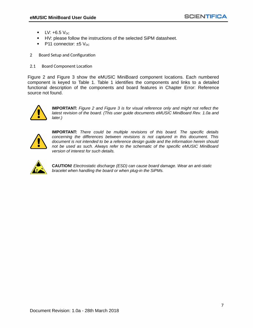
LV: +6.5 VDC HV: please follow the instructions of the selected SiPM datasheet. P11 connector: ±5 VDC
2 Board Setup and Configuration
2.1 Board Component Location
Figure 2 and Figure 3 show the eMUSIC MiniBoard component locations. Each numberedcomponent is keyed to Table 1. Table 1 identifies the components and links to a detailedfunctional description of the components and board features in Chapter Error: Referencesource not found.
IMPORTANT: Figure 2 and Figure 3 is for visual reference only and might not reflect thelatest revision of the board. (This user guide documents eMUSIC MiniBoard Rev. 1.0a andlater.)
IMPORTANT: There could be multiple revisions of this board. The specific detailsconcerning the differences between revisions is not captured in this document. Thisdocument is not intended to be a reference design guide and the information herein shouldnot be used as such. Always refer to the schematic of the specific eMUSIC MiniBoardversion of interest for such details.
CAUTION! Electrostatic discharge (ESD) can cause board damage. Wear an anti-static bracelet when handling the board or when plug-in the SiPMs.
7Document Revision: 1.0a - 28th March 2018

eMUSIC MiniBoard User Guide
Figure 2: eMUSIC MiniBoard top components location.
Figure 3: eMUSIC MiniBoard bottom components location.
8Document Revision: 1.0a - 28th March 2018
eMUSIC MiniBoard User Guide
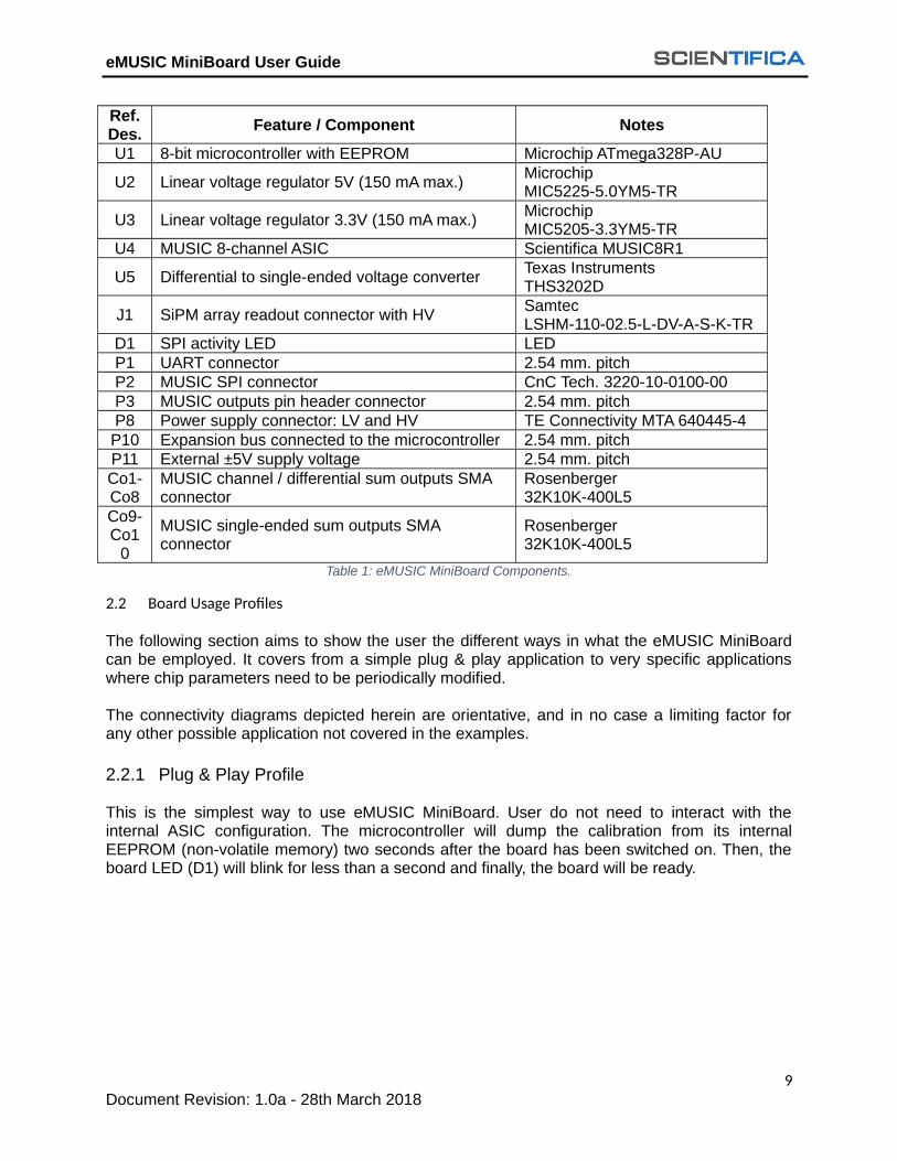
Ref.Des.
Feature / Component Notes
U1 8-bit microcontroller with EEPROM Microchip ATmega328P-AU
U2 Linear voltage regulator 5V (150 mA max.)MicrochipMIC5225-5.0YM5-TR
U3 Linear voltage regulator 3.3V (150 mA max.)MicrochipMIC5205-3.3YM5-TR
U4 MUSIC 8-channel ASIC Scientifica MUSIC8R1
U5 Differential to single-ended voltage converterTexas InstrumentsTHS3202D
J1 SiPM array readout connector with HVSamtecLSHM-110-02.5-L-DV-A-S-K-TR
D1 SPI activity LED LEDP1 UART connector 2.54 mm. pitchP2 MUSIC SPI connector CnC Tech. 3220-10-0100-00P3 MUSIC outputs pin header connector 2.54 mm. pitchP8 Power supply connector: LV and HV TE Connectivity MTA 640445-4P10 Expansion bus connected to the microcontroller 2.54 mm. pitchP11 External ±5V supply voltage 2.54 mm. pitchCo1-Co8
MUSIC channel / differential sum outputs SMA connector
Rosenberger32K10K-400L5
Co9-Co1
0
MUSIC single-ended sum outputs SMA connector
Rosenberger32K10K-400L5
Table 1: eMUSIC MiniBoard Components.
2.2 Board Usage Profiles
The following section aims to show the user the different ways in what the eMUSIC MiniBoardcan be employed. It covers from a simple plug & play application to very specific applicationswhere chip parameters need to be periodically modified.
The connectivity diagrams depicted herein are orientative, and in no case a limiting factor forany other possible application not covered in the examples.
2.2.1 Plug & Play Profile
This is the simplest way to use eMUSIC MiniBoard. User do not need to interact with theinternal ASIC configuration. The microcontroller will dump the calibration from its internalEEPROM (non-volatile memory) two seconds after the board has been switched on. Then, theboard LED (D1) will blink for less than a second and finally, the board will be ready.
9Document Revision: 1.0a - 28th March 2018

eMUSIC MiniBoard User Guide
Figure 4: eMUSIC MiniBoard Plug & Play Profile simplified block diagram.
2.2.2 Limited Programmability Profile (UART)
In this mode user can modify eMUSIC MiniBoard configuration over UART interface, using theATmega328P microcontroller as a bridge (see Figure 5). Moreover, the non-volatileconfiguration stored into the EEPROM can also be modified. The eMUSIC MiniBoard EvaluationBoard needs to be connected to an external UART to USB board (FTDI FT232RL USB). Thisauxiliary board can be connected to a PC running a 64-bit Windows or Linux operating systems.Table 2 shows the Operating Systems Software Compatibility List.
IMPORTANT: Special care must be taken when connecting the USB interface board toeMUSIC MiniBoard Evaluation Board. Be sure that DTR and GND pins serigraphy match.Connecting the boards in another way may irreversibly damage the boards. Further detailscan be found in Section .
IMPORTANT: The microcontroller EEPROM memory has a specified life of 100,000write/erase cycles, so you may need to be careful about how often you write to it.
Operating System Architechture CompatibleUbuntu 16.04 LTS 64-bit Yes
Windows 7 64-bit YesWindows 10 64-bit Yes
Table 2: Operating Systems Software Compatibility List.
10Document Revision: 1.0a - 28th March 2018

eMUSIC MiniBoard User Guide
The eMUSIC MiniBoard Evaluation Board can be configured over eMUSIC MiniBoard software,a CLI available here. The software allows to configure ASIC via SPI interface: gain, pole/zero,switch on/off channels, sum of channels, etc. It also allows to perform calibrations and storepermanently any configuration into the non-volatile memory. Detailed instructions can be foundin the Appendix A.
Figure 5: eMUSIC MiniBoard Limited Programmability Profile (UART) simplified block diagram.
2.2.3 Full Programmability Profile (SPI)
In this mode the embedded microcontroller is bypassed and the external master takes control ofthe SPI bus, and thus the non-volatile configuration dump is disabled. This profile is suitable forapplications where periodical reconfiguration of a large number of boards is required. In thismode user has to develop his/her own ASIC control library/driver/API.
User can reset or change any chip parameter by connecting an external SPI master to the pinheader provided. Bypass pin must be asserted to claim the SPI bus and power down themicrocontroller. More details can be found in Section 3.2.
IMPORTANT: SPI interface pins, ASIC reset and microcontroller bypass IO standard is3.3V CMOS. Higher IO voltages may damage the eMUSIC MiniBoard Evaluation Board.
IMPORTANT: Wrong ASIC configuration may lead to misfunctioning or even to permanentboard damage. Please, be careful when programming the chip and follow carefully theeMUSIC datasheet.
11Document Revision: 1.0a - 28th March 2018

eMUSIC MiniBoard User Guide
Figure 6: eMUSIC MiniBoard Full Programmability Profile (UART) simplified block diagram.
2.2.4 eMUSIC MiniBoard Outputs
The eMUSIC MiniBoard can have up to 10 simultaneous SMA outputs, and 7x2 pin header(2.54 mm pitch) containing the same outputs plus the trigger channel fast OR signal.
The number of soldered SMA connectors may depend on user needs. It is important to highlightthat some of the eMUSIC chip outputs are multiplexed and the SMA output purpose is defied(hardcoded) during the PCB manufacturing process. The multiplexed eMUSIC chip outputs (seeFigure 2) are listed below. Please note it is only possible to select one option, single-ended ordifferential, by using the corresponding resistor (then, the other resistor cannot be soldered).
Ch#2 single-ended output (VoSE[2]) and differential sum high-gain positive pin (VoHG+). Ch#3 single-ended output (VoSE[3]) and differential sum high-gain negative pin
(VoHG-). Ch#4 single-ended output (VoSE[4]) and differential sum high-gain positive pin (VoLG+). Ch#5 single-ended output (VoSE [5]) and differential sum high-gain negative pin
(VoLG-).
12Document Revision: 1.0a - 28th March 2018

eMUSIC MiniBoard User Guide
Signal Name Output Configuration Requirement(s)
VoSE[0]Single-ended analog Co1 SMA
R6 0Ω resistorSingle-ended discriminated
VoSE[1]Single-ended analog Co3 SMA
R7 0Ω resistorSingle-ended discriminated
VoSE[2]Single-ended analog Co2 SMA
R8 0Ω resistorSingle-ended discriminated
VoSE[3]Single-ended analog Co4 SMA
R9 0Ω resistorSingle-ended discriminated
VoSE[4]Single-ended analog Co6 SMA
R10 0Ω resistorSingle-ended discriminated
VoSE[5]Single-ended analog Co8 SMA
R11 0Ω resistorSingle-ended discriminated
VoSE[6]Single-ended analog Co5 SMA
R12 0Ω resistorSingle-ended discriminated
VoSE[7]Single-ended analog Co7 SMA
R13 0Ω resistorSingle-ended discriminatedVoHG+VoHG-
Differential analogCo2, Co4 SMAs
R1, R2 0Ω resistorVoLG+VoLG-
Differential analogCo6, Co8 SMAs
R3, R5 0Ω resistor
VoHG Single-ended analogCo10 SMAP11 (±5V)
VoLG Single-ended analogCo9 SMAP11 (±5V)
Table 3: eMUSIC MiniBoard Evaluation Board Outputs Configuration.
IMPORTANT: User has to make sure the FT232RL module board power supply jumper(JP1) is connected to +3.3V. Jumper connected to +5V may damage the board.
NOTE: differential to single-ended channel sum output conversion requires negative voltagesupply. This voltage is supplied through an external ±5V voltage supply connected to the 3-waypin header (P11).
3 Board Component Descriptions
3.1 Power supply connectors
The power supply connector mounted on eMUSIC MiniBoard is the MTA 640445-4, a 4-positionheader connector with 3.96mm pitch (Figure 7). The correspondent female connector modelscould be the MTA 3-640429-4 and the TE Connectivity AMP Connectors 647466-2.
13Document Revision: 1.0a - 28th March 2018

eMUSIC MiniBoard User Guide
(a) (b) (c) Figure 7: Header connector (a), the correspondent receptacle connector (b), and socket contact (c).
Error: Reference source not found shows the layout and Table 4 shows the pin assignment ofthe power supply connector (P8).
1GND
2 LV
3GND
4 HV
Figure 8: Power supply connector layout.
#Pin(s) Signal Name Description1, 3 GND PCB ground
2 LV Voltage range: +6.5 VDC
4 HV SiPM High Voltage. Check selected SiPM datasheetTable 4 Pin assignment of the power supply connector.
For those users who want to output the summation of the channels in single-ended mode aseparate power supply for the summation in single-ended mode needs to be provided (P11).Figure 9 shows the layout and Table 5 shows the pin assignment of the power supply connector.
1 +5V
2 GND
3 -5V
Figure 9: Differential to single-ended channel sum converter power supply connector layout.
#Pin(s) Signal Name Description1 +5V +5 VDC
2 GND PCB ground3 -5V -5 VDC
Table 5 Pin assignment of the differential to single-ended channel sum converter power supply connector.
14Document Revision: 1.0a - 28th March 2018

eMUSIC MiniBoard User Guide
3.2 External SPI interface
The external SPI interface PCB connector is the CNC Tech 3220-10-0100-00, a 10-positionheader connector (1.27 mm pitch). The correspondent female connector could be the CNC Tech3230-10-0103-00.
(a) (b)
Figure 10: External SPI connector for PCB (a) and female connector (b).
The eMUSIC chip is compatible with SPI Mode 1 (CPOL = 0, CPHA = 1). Figure 11 shows anexample of a read & write and read-only access. Further information can be found in eMUSICdatasheet.
Figure 11: An example of register read+write access (top) and register read only access (bottom).
Figure 12 shows the layout and Table 6 shows the pin assignment of the external SPI interfaceconnector. Special attention must be taken with bypass pin (BYP). This pin must be at high levelwhen controlling the ASIC externally. The digital voltage standard is CMOS 3.3 Volts.
1 GND GND 2
15Document Revision: 1.0a - 28th March 2018

eMUSIC MiniBoard User Guide
3 GND GND 4
5 GNDSCL
K 6
7 MOSI
GND 8
9 MISO
!RST 10
11 !SS GND 12
13 BYP GND 14
Figure 12: External SPI connector header layout (P2).
#Pin(s) Signal Name Description1,2,3,4,5,8,12,1
4GND PCB ground
6 SCLK SPI interface serial clock. FCLK ≤ 30 MHz7 MOSI SPI Master Output / Slave Input9 MISO SPI Master Input / Slave Output
10 !RSTBoard reset (active low). It is equivalent to push the reset button (SW1)
11 !SS SPI Slave Select (active low)
13 BYPMicrocontroller bypass. When asserted (high), the microcontroller powers down and grants the SPI bus to the external SPI master. Mandatory for external SPI control
Table 6 Pin assignment for the external SPI connector (P2).
3.3 UART Connector
The user has to use a basic board for the FTDI FT232RL USB to serial IC to work with themicrocontroller on the eMUSIC MiniBoard and this board needs to be connected to the eMUSICMiniBoard P1 connector. The UART connector layout is shown in Figure 13 and pin assignmentfor the connector is shown in Table 7.
IMPORTANT: User has to make sure the FT232RL module board power supply jumper(JP1) is connected to +3.3V. Jumper connected to +5V may damage the board.
IMPORTANT: Special care must be taken when connecting the USB interface board toeMUSIC MiniBoard Evaluation Board. Be sure that DTR and GND pins serigraphy match.Connecting the boards in another way may irreversibly damage the boards.
16Document Revision: 1.0a - 28th March 2018

eMUSIC MiniBoard User Guide
6 DTR
5 TXO
4 RXI
3 VCC
2 GND
1 GND
6
5
4
3
2
1
Figure 13: UART connector (P1) layout and PCB picture.
#Pin(s) Signal Name Description1,2 GND PCB ground3 VCC +3.3 VDC
4 RXIReceive Asynchronous Data Input (USB eMUSIC MiniBoard)
5 TXOTransmit Asynchronous Data Input (USB eMUSIC MiniBoard)
6 DTRData Terminal Ready Control. When asserted, it resets the microcontroller
Table 7 Pin assignment for the UART connector (P1).
3.4 SiPM Readout Connector
The SiPM readout connector is a board-to-board terminal/socket strip, specifically the LSHM-110-02.5-L-DV-A-S-K-TR.
Figure 14: SiPM readout connector (J1).
1 GND GND 2
17Document Revision: 1.0a - 28th March 2018
JP1

eMUSIC MiniBoard User Guide
3 IN[0] GND 4
5 IN[1] GND 6
7 IN[2] HV 8
9 IN[3] HV 10
11 IN[4] HV 12
13 IN[5] HV 14
15 IN[6] GND 16
17 IN[7] GND 18
19 GND GND 20
Figure 15: External SPI connector header layout (J1).
#Pin(s) Signal Name Description1,2,4,6,16,18,19,20
GND PCB ground
3,5,7,9,11,13,15,1
7IN[0:7] SiPM cathodes, ASIC inputs
8,10,12,14 HV SiPM High Voltage. Check selected SiPM datasheetTable 8 Pin Assignment for the SiPM Readout Connector (J1).
3.5 Microcontroller
The microcontroller has two roles. First, it masters the SPI bus which configures eMUSIC ASIC,and second, it stores the non-volatile eMUSIC configuration. Additionally, these functionalitiescan be disabled when an external SPI master is connected into the eMUSIC MiniBoard. Themicrocontroller SPI configuration flow diagram is shown in Figure 16. The flow path can bedivided into three modes depending on the bypass control signal (see Section 3.2) which grantsaccess to the external SPI bus, and the microcontroller goes into power down state.
MODE 1, when bypass = ‘1’:
When eMUSIC MiniBoard is powered on, microcontroller peripherals are initialized. Inthe INIT state it checks if any external system has asserted the BYP control signal. If so,then the microcontroller is powered down and the external SPI master can take controlof the eMUSIC ASIC.
MODE 2, when bypass = ‘0’:
18Document Revision: 1.0a - 28th March 2018

eMUSIC MiniBoard User Guide
When eMUSIC MiniBoard is powered on, microcontroller peripherals are initialized. Inthe INIT state it checks for the BYP control signal. If the control signal is at low-level(‘0’), the microcontroller will consider that there is no external SPI master present totake control of the SPI bus. In this mode the microcontroller has control over the SPIbus. In this mode there are two functions it performs:
Default Configuration mode: The controller waits for 2 seconds after power-onor reset. After that, it checks if user has issued any software command. If not, itloads the default calibration file from microcontroller EEPROM which has beenpreviously stored.
User Configuration mode: If user issues any software command(mini_music_sw) within the 2 seconds after board power-on or reset, then themicrocontroller configures the board as per the user configuration. It is importantto highlight that the software resets the board automatically by means of DTRline, so user needs not to press reset button with each command.
Figure 16: Microcontroller flow diagram.
4 Measurements Procedure
This Chapter briefly explains the steps that user needs to follow to perform measurements.
19Document Revision: 1.0a - 28th March 2018

eMUSIC MiniBoard User Guide
1. Wear an anti-static bracelet to handle the board. The omission of this step may
produce permanent damage to eMUSIC ASIC or any other components in the board.2. Prepare the setup: connect the external boards required for your test. E.g. SiPMs,
external SPI, etc. 3. Connect the power supply connector (P8) LV pins to a low-voltage power supply (5 - 6
VDC), and HV pins to a high-voltage power supply.4. If the board needs to be connected to a PC, a USB cable to an available port on a
computer.5. Configure the electronics (this will depend on the user board usage profile).6. Use the oscilloscope to measure the different output signals.
IMPORTANT: Please do not POWER ON the board without limiting the LV and HV supplysource current.
a. Maximum current limit for LV supply source is 0.5 A (max.).b. Maximum current limit for HV supply source is 1 mA (max.).
IMPORTANT: Please do not power the board only from the USB port.
IMPORTANT: Please do not turn ON the LV when the HV is at 0 V, always make sure thatHV is at 2V, never lower.
IMPORTANT: Never leave the board power ON with HV at 0V.
IMPORTANT: Please never short circuit the diode ANODE & CATHODE pins of the SiPMreadout board during any kind of measurements.
20Document Revision: 1.0a - 28th March 2018

eMUSIC MiniBoard User Guide
A. eMUSIC MiniBoard Commands
This Appendix regards to the board usage profile where eMUSIC MiniBoard is configured usingthe UART interface (see Section 2.2.2).
The list of available commands is the following:
Command Descriptionmini_music version Shows current software versionmini_music read_serial Reads eMUSIC MiniBoard Serial Numbermini_music reset Resets eMUSIC ASICmini_music show_config [args] Shows eMUSIC ASIC configurationmini_music config <args> Configures eMUSIC ASIC electronicsmini_music config_file <args> Configures the ASIC from a configuration filemini_music threshold_scan [args] Runs a threshold scan of the binary discriminated outputmini_music vdc_calib [args] Calibrates the VDC of the eMUSIC analog channel outputs
Table 9: eMUSIC MiniBoard Evaluation Board software commands.
All the above-mentioned commands have the following generic options and they will be omitted in the explanation of the commands:
[-h], [--help] Shows the command help message.
[-P], [--port] Which serial port to use. E.g.: COM4 (Windows), /dev/ttyUSB0 (Linux).
[-l], [--loglevel] Log level (trace, debug, verbose, info, warning, error, fatal, disable).
[-F], [--logformat] Log format ('-' to disable any header).
[-C], [--args_file] File containing the arguments to parse. Same format as the command line flags.
Example User has problems trying to connect with the board and wants to troubleshoot the problem. Inthis case, we suggest changing the default log level (info) to debug, and specify manually theUART interface number:
mini_music read_serial -l debug -P /dev/ttyUSB0
mini_music version:
Command mini_music version
Returns the git hash corresponding to the software version. In case you need support, please, tell us which version you are using.
Example mini_music version
History Legacy command.
mini_music reset:
Command mini_music reset
Resets the eMUSIC ASIC. After issuing this command, the ASIC will run the original foundryparameters. Thus, the chip may not be properly calibrated. This command has no effect on themicrocontroller’s EEPROM.
Example mini_music reset
History Legacy command.
21Document Revision: 1.0a - 28th March 2018

eMUSIC MiniBoard User Guide
mini_music show_config:
Command mini_music show_config [-f <file_name>] [-E]
Shows eMUSIC configuration. By default, it shows the ASIC configuration, not EEPROM.[-f]
[--dump_file]Dumps the configuration shown in the screen into an output file. When this option is asserted, apath to a writable file name must be provided.
[-E][--read_eeprom]
Shows the configuration stored into the EEPROM instead of the currently configured in theeMUSIC ASIC.
Example This example stores the current ASIC parameters into a file named good_params.calib:
mini_music show_config -f ./calib/good_params.calib
History Legacy command.
mini_music config_file:
Command mini_music config_file <-f file_name> [-E] [-a]
Changes eMUSIC configuration from a file. By default, it applies the configuration to the ASIC,
not EEPROM.[-f]
[--file]The path to the configuration file name to be applied.
[-E][--store_eeprom]
When provided, the configuration file provided will be flashed into the microcontroller EEPROM,so that the configuration will be stored permanently.
[-a][--auto_reload]
When provided, eMUSIC ASIC configuration will be updated from the file every time the filechanges. This option is suitable when user wants to optimize the performance of the chip by trialand error method. This option is incompatible with -E option in order not to stress the EEPROM(it has a finite number of write/erase cycles). In this mode, the application will remain opened,waiting for a change in the configuration file. To exit the application, press CTRL+C.
Example 1 This example loads a given configuration file into the EEPROM:
mini_music config_file -f ./calib/last_calib_version_v3_final_final_final_2.calib -E
Example 2 This example loads music_scratch.txt into the ASIC every time this file changes:
mini_music config_file -f /tmp /music_scratch.txt -a
History Legacy command.
mini_music config:
Command mini_music config [-d] [-p <R C>] [-t] [-a] [-f] [-g] [-v <vth0>…<vth7>] [-o < voff0>…<voff7>] [-e
<ch_list>] [-u <ch_list>] [-E]
Changes eMUSIC configuration from the command options provided. By default, it applies theconfiguration to the ASIC, not EEPROM.
[-d][--digital]
When specified, eMUSIC Single-Ended outputs (VoSE[7:0]) are configured as binarydiscriminated.
[-p][--polezero]
When specified, eMUSIC Pole/Zero filters are enabled. This command requires two values: R
22Document Revision: 1.0a - 28th March 2018

eMUSIC MiniBoard User Guide
(from 0 to 7) and C (from 0 to 31).
[-t][--hightrans]
When specified, single-ended and differential channels are configured in high transimpedancemode (higher gain). Otherwise, they are configured as low transimpedance.
[-a][--lowlad]
When specified, Pole-Zero attenuation is reduced.
[-f][--vdcfile]
Specify the eMUSIC Single-Ended VDC calibration file name (*.vdc). This file contains a lookuptable with the optimal analog VDC chip parameters for any of the Pole/Zero combinations. If thisconfiguration file is not provided, please, run vdc_calib command to calibrate the chip with theoptimal parameters for you.
[-g][--vbg]
To adjust the bandgap voltage of the comparators when eMUSIC outputs are configured asbinary discriminated. Threshold scan test will suggest you the proper configuration of thisparameter.
[-v][--vthchannels]
To adjust the threshold (per-channel, from 0 to 511) of the discriminator when eMUSIC outputsare configured as binary discriminated. Threshold scan test provides the channels’ VTH valuewhere the output comparator commutates from low to high. Using smaller values than the onesshown in the threshold scan, the comparator will be able to detect small signals at the input.
[-o][--voffchannels]
Select per-channel the anode input voltage VOffset (from 0 to 511). 8 arguments (one for eachchannel) are required to use this configuration option.
[-e][--chan_enable]
Select the list of eMUSIC channels to enable (0-7).
[-u][--sumchans]
The list of eMUSIC channels to be summed (0-7).
[-E][--store_eeprom]
When provided, the configuration file provided will be flashed into the microcontroller EEPROM,so that the configuration will be stored permanently.
Example 1 This example configures eMUSIC in analog mode, with Pole/Zero filter enabled and hightransimpedance configuration. Only channels from 0 to 3 are enabled, and the sum output ismade from channels 0 and 1:
mini_music config -p 5 12 -t -e 0 1 2 3 -u 0 1
Example 2 This example writes to the eMUSIC configuration EEPROM. The stored values will configure
eMUSIC in digital mode, with the bandgap voltage to 5 and it will also configure each of the
8-channel thresholds:
mini_music config_file -d -g 5 -v 120 127 122 135 131 124 141 138 -E
History Legacy command.
mini_music threshold_scan:
Command mini_music threshold_scan
Runs a threshold scan of the binary discriminated output. This command only makes sensewhen eMUSIC outputs are configured as binary discriminated. It performs a sweep of thecomparator VTH to find the value where the output channel transition. This test has to be done inabsence of signal at the chip input.
Example mini_music threshold_scan
History Legacy command.
23Document Revision: 1.0a - 28th March 2018

eMUSIC MiniBoard User Guide
mini_music vdc_calib:
Command mini_music vdc_calib [-E]
Calibrates the offset of the analog outputs, either single-ended or differential, to maximize therail-to-rail voltage swing.
[-E][--store_eeprom]
When provided, the optimal VDC configuration computed in this test will be flashed into themicrocontroller EEPROM, so that the configuration will be stored permanently.
Example mini_music threshold_scan
History Legacy command.
24Document Revision: 1.0a - 28th March 2018