Embed Size (px)
Citation preview

Control Dewar
Beam Injection
DC current
Rf power
Rf power
Liq. HeSRCCryogenic activities in RIKEN RI beam factory
Table of Contents
1: Overview of RIBF and SRC
2: Operation of SRC cryogenic cooling system
3: Current issues in the cryogenic system for SRC
4: A new He refrigerator for SRF linac
H. OKUNO
RIKEN, Nishina Center for Accelerator-based Science

RIKEN RI Beam Factory (RIBF) (2006-)The world’s most intense RI Beams over the whole range of atomic masses to
open and develop new fields of nuclear science
Powerful Heavy Ion Accelerator (Projectile Fragmentation or in-flight fission)
18GHz ECRIS
RILAC
RRC
fRC
IRC
SRC
400MeV/u (Light Ion)
345MeV/u (Very Heavy Ion, Uranium)
I = 1pmA (6 x 10¹² #/s)
New Cyclotron System
18GHzECR+RILAC+RRC+fRC+IRC+SRC
Ion beam Target
RI beam
Target

SC magnets with cryogenic system for RIBF
28GHz SC ECR ion source
GM/JT-cooler ([email protected])
SRC with TCF200s
(1000W@4K)
5 STQs for BigRIPS
with TCF50 (320 W@4K)
21 STQs for BigRIPS
with 21 GM/JT-coolers
(2.5 W@4K)
1 SDQ for SHARQ
with (2.5 W@4 K)
SAMURAI magnet
with 2 GM/JT-coolers (2.5 [email protected])
RIBF needs SC magnets
High magnetic rigidity (large M/Q)
Energy Saving
Large aperture for secondary beams
25 GM/JT-coolers
2.5 x 25 = 63 W@4K

Superconducting
Bending Magnet
Control DewarSide Shield
(Open for maintenance)
SC Main Coil
SC Trim CoilLower Shield
RF-Cavity
Upper Shield
Upper Yoke
Side Yoke
Lower Yoke
The World’s First Superconducting Ring Cyclotron (SRC) H. Okuno et al., IEEE Trans. Applied Superconductivity, 17 (2007) 1063
Self Magnetic ShieldSelf Radiation Shield
Sector Magnets :6RF Resonator :4Injection elements.Extraction elements.
Main Spec. of SRCK = 2,600 MeVMax. Field: 3.8 T (235 MJ)RF frequency: 18-38 MHzTotal Acc. Volt.: 640 MVWeight: 8,300 tonsDiameter: 19 m Height: 8 m
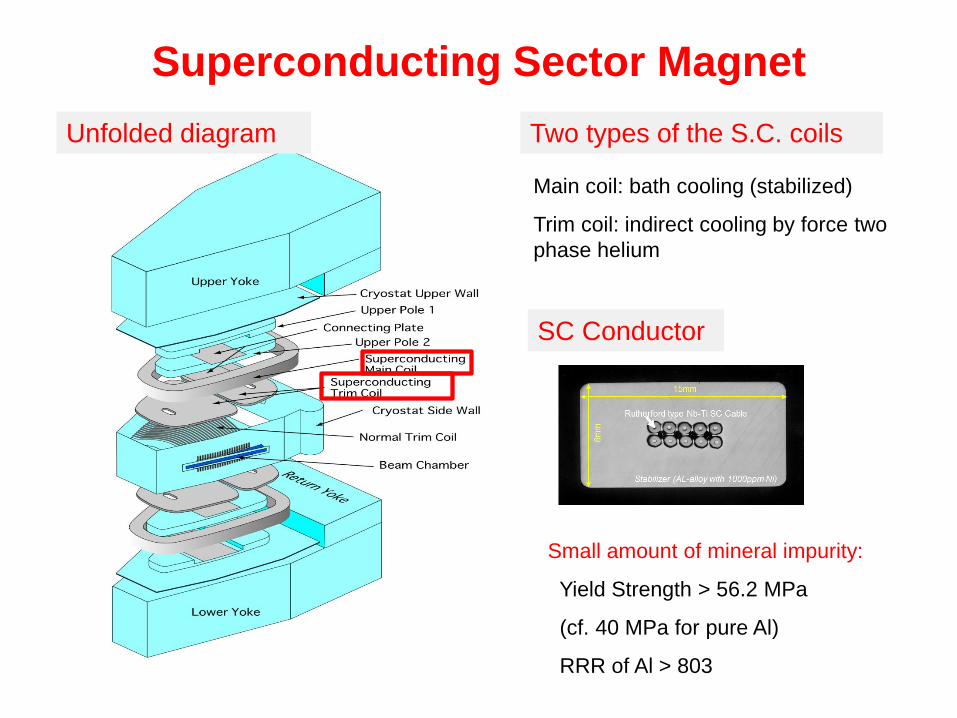
Superconducting Sector Magnet
Unfolded diagram
SC Conductor
Small amount of mineral impurity:
Yield Strength > 56.2 MPa
(cf. 40 MPa for pure Al)
RRR of Al > 803
Two types of the S.C. coils
Main coil: bath cooling (stabilized)
Trim coil: indirect cooling by force two
phase helium

Assembling of SRC in the vault

Reservoir Tanks
Compressor
Refrigerator
Turbine JT-valveHeat exchanger
Control dewar
SRC
R.T. 4.5 K100 m3 (2 MPa) x 4
74 g/s of 1.65 MPa GHe
He cooling system for the SRC
Cooling Capacity Heat Load
@4.5 K 620 W (1.3 x H.L.) 470 W
@ 70 K 4000 W 2800 W
For cooling of P. L. 4 g/s 3 g/s
Initial cooling 21 days (142 ton)

0
50
100
150
200
250
300
350
H17.9.15 H17.9.20 H17.9.25 H17.9.30 H17.10.5 H17.10.10 H17.10.15
Day
Tem
p (K
)
TI_A1P01
TI_A1P02
TI_A1P03
TI_A1P04
TI_A1P05A
TI_A1P05B
TI_A2P01
TI_A2P02
Calc.
T(Sup.)
T (Cold Mass, Ret.)
Calculation
23 Days
DT< 50K
Cool-down curve in the first trial

Control Dewar
Beam Injection
DC current
Rf power
Rf power
Liq. HeSRC
Beam profile at the exit of SRC
The First Beam 2006/12/28!

Intensity upgrade at RIBF
RILAC2RRC
SCECR
fRC IRC
SRCHe gas Rotating Be diskAccelerators
He gas stripperRotating Be diskfRC upgrade(K570=>K700)
RIBF starts!
The new injector(RILAC2) starts!
Transmission of the beam: improvedStability of the devices: improved
Germany/GSI
28-GHz SC-ECR
73 pnA U (~4x10¹¹#/s 2017)
supported by the continuous efforts for stable operation of cryogenic system.

Summary of 10 year operation Season Operation (h) Steady operation
(h)No. of
failure Repair (h) Availability
05/'06 4293.5 1858.6 2 188.3 0.958
2005/11/8 - 2006/3/10: broken ceramics of a feedthrough in the liquid He vessel
06/'07 7804.8 6452.6 5 1089.9 0.877
07/'08 1274.0 405.3 0 0.0 1.000
2008/2/11 - 2008/8/20: Oil contamination in the He refrigerator and making additional oil separator
08/'09 6785.1 5180.3 0 0.0 1.000
09/'10 5515.1 3659.9 1 20.2 0.996
10/'11 6505.3 4537.5 1 2.6 1.000
11/'12 7463.7 5154.1 1 144.2 0.981
12/'13 6240.8 3315.5 1 169.0 0.974
13/'14 3672.6 2475.9 5 99.9 0.974
14/'15 6553.3 4031.2 5 11.9 0.998
Total 56108.4 37071.1 21.0 1725.9 0.970

What happened on 8th November , 2005(7th Nov, 2005: The 1st excitation to the maximum current)
All turbines tripped, liquid He level quickly fell to zero, and thermal insulation vacuum worsened.
The emergency valve opened.

A feed through attached the Liq. He vessel
Wall of the liq. He vessel (2000 L)
The feed through for the indirectly cooled S.C. trim coils
CeramicsCupper Crack

Don’t repair it, replace it.
Smaller ceramics => small risk

Flow rate through the first turbine
(Manually adjusted)
Oil contamination in the He refrigerator
The He refrigerator was contaminated with oil from the He compressor. (Feb. 2008)
2005-2007
2008
Heat exchangers : washCharcoal in the 80K adsober : replaceOil separator of the He comp. : 4step→6 step

HX1-3
HX4-5
Heat exchanger in the He refrigerator
Cut the heat exchanger unit from the refrigerator
Battle against the oil in the He refrigerator
Cleaning process in a factoryAccess to the lower temperature region
Oil in the refrigerator: 2000 cc => 4 cc

5th
Sep
erat
or
4th
Sep
erat
or
3rd
Sepe
rato
r
1st
Sep
erat
or
2nd
Sepe
rato
r
1.5
th S
epe
rato
r
Compressor
Unit A
Uni
t B
Uni
t C
High Pressure Line
Low Pressure Line
Additional oil separator in He compressor unit
Demister
Coalescer
Charcoal+
Mole. Sheave
Charc
oal
Ne
w
New
Oil contamination: 100 ppb -> 20ppb

Current issues in the operation
• Radiation damage of epoxy bonding in the superconducting trim coils
• Malfunction of the cryogenic control system
• Shortage of He gas

Neutron damage to SC trim coil
Support plate (Al-alloy)
Cooling tubeInsulator
Screw
The epoxy bonding is important to coolthe coil. Its radiation hardness should be Studied.
Cross section of SC trim coil
Lifetime of epoxy glue = lifetime of SRC

Electrostatic deflection channel and SC trim coil
EDC for Beam extraction
Beam loss point
SC trim coil
Be
am
Al sample to monitor neutron flux
g Emitted in the b decay of 22Na made in the reaction of 27Al (n, 4n2p)22Na
Dose to Sc Trim coil < 0.1 MGy/10 yearWe can use it for more than 100 years.
Valley of SRC
Sector magnet of SRC

He refrigerator
Cryogenic Control system for SRC
LAN for cryogenic control
VME1
I/O panel
VME2
I/O panel
Reflective memory
Cont. Panel for P.S.s
SRC
Valve controlTemp. monitoretc.
Valve controlTemp. monitoretc.
DC Power SuppliesQuench Detectors
PC
PC
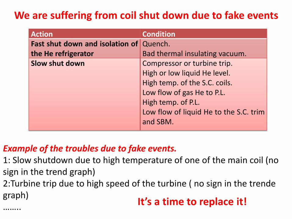
We are suffering from coil shut down due to fake events
Action ConditionFast shut down and isolation ofthe He refrigerator
Quench.Bad thermal insulating vacuum.
Slow shut down Compressor or turbine trip.High or low liquid He level.High temp. of the S.C. coils.Low flow of gas He to P.L.High temp. of P.L.Low flow of liquid He to the S.C. trimand SBM.
Example of the troubles due to fake events.1: Slow shutdown due to high temperature of one of the main coil (no sign in the trend graph)2:Turbine trip due to high speed of the turbine ( no sign in the trendegraph)…….. It’s a time to replace it!

Shortage of helium gasThe cooling system is closed cycle but tiny leak is inevitable.
Trend of price and import of Helium gas.
We were operating with a He leak from 2012 to 2013. We need supply 1000 m3/year in operation.
Now we can not operate the system with such leak.
He gas volume in the buffer tank

Helium refrigerator Joint box
Valve boxes
Transfer tube
Coaxial line
New He refrigerator for Superconducting LINAC
First He refrigerator from Air liquide
By courtesy of Yonekura (AirLiquide Japan)

RILAC upgrade
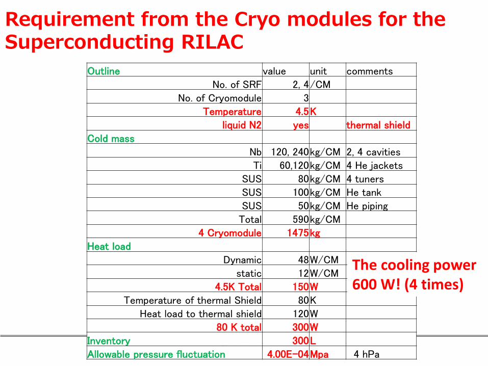
Requirement from the Cryo modules for the Superconducting RILAC
Outline value unit commentsNo. of SRF 2, 4/CM
No. of Cryomodule 3Temperature 4.5K
liquid N2 yes thermal shieldCold mass
Nb 120, 240kg/CM 2, 4 cavitiesTi 60,120kg/CM 4 He jackets
SUS 80kg/CM 4 tunersSUS 100kg/CM He tankSUS 50kg/CM He pipingTotal 590kg/CM
4 Cryomodule 1475kgHeat load
Dynamic 48W/CMstatic 12W/CM
4.5K Total 150WTemperature of thermal Shield 80K
Heat load to thermal shield 120W80 K total 300W
Inventory 300LAllowable pressure fluctuation 4.00E-04Mpa 4 hPa
The cooling power 600 W! (4 times)

Cooling diagram
He
bu
ffer
tan
k
Load valve
Unload valve
He comp. Oil sep.
Co
ld b
ox
LN2 CE tankLN2 Vent. tank
4 cavities 4 cavities 2 cavities
4.5 K gas He returnLiq. He supply
Pre
coo
ling
80K shield cooling
80K shield cooling
Liq
. He
sup
ply
4.5
K g
as H
e re
turn

Commissioning test of Cold BoxThe refrigeration system is consisted by screw compressor and cold box.
main feature is in below
Compressor : 1.75MPa (18.5BarA)
74.2g/s
Cold box [email protected]
This cold box is consisted by the 2 turbines in series with JT valve.
During the commissioning process, we had achieved to
- 700W @ 4.5K by the heater in Phase separator.
This is only operation of cold box for checking the performance, but system operation condition is shown in left graph and it is demonstrated of stable operation
By courtesy of Yonekura (AirLiquide Japan)

Commissioning test of whole systemTotal cooling test was organized at the same time to cooling down with CB.
After starting the turbine, system was reached to 4.5K in cold part and filled by the LHe on CMs.
With achieving following criteria, we had measured of performance.
CB operates maximum power.
to keep the LT 88% at CM.
pressure in CM 24.6kPa (1.26barA)
phase separator keeps 50% of LHe.
then, we measured the performance with keeping the criterion and we could record that CB seemed to be still kept of [email protected] as average in its cold power
By courtesy of Yonekura (AirLiquide Japan)

Summary•The SRC was successfully operated for 12 years as the final booster of RIKEN RIBF accelerator complex after the first beam at the end of 2006. •The operation of the cryogenic cooling system was also stable despite the two big troubles.
•The He leak to the thermal insulation vacuum of the magnet through a tiny crack in the feed through attached to the liquid He vessel. •The oil contamination in the He refrigerator.
•The current issues for superconducting magnets •Radiation hardness of the superconducting trim coils •Trouble in the cryogenic control system•Shortage of helium gas
•The He refrigerator for the SRF in RILAC were successfully installed and commissioned. The new RILAC will have the first beam around the end of this year.