Embed Size (px)
Citation preview
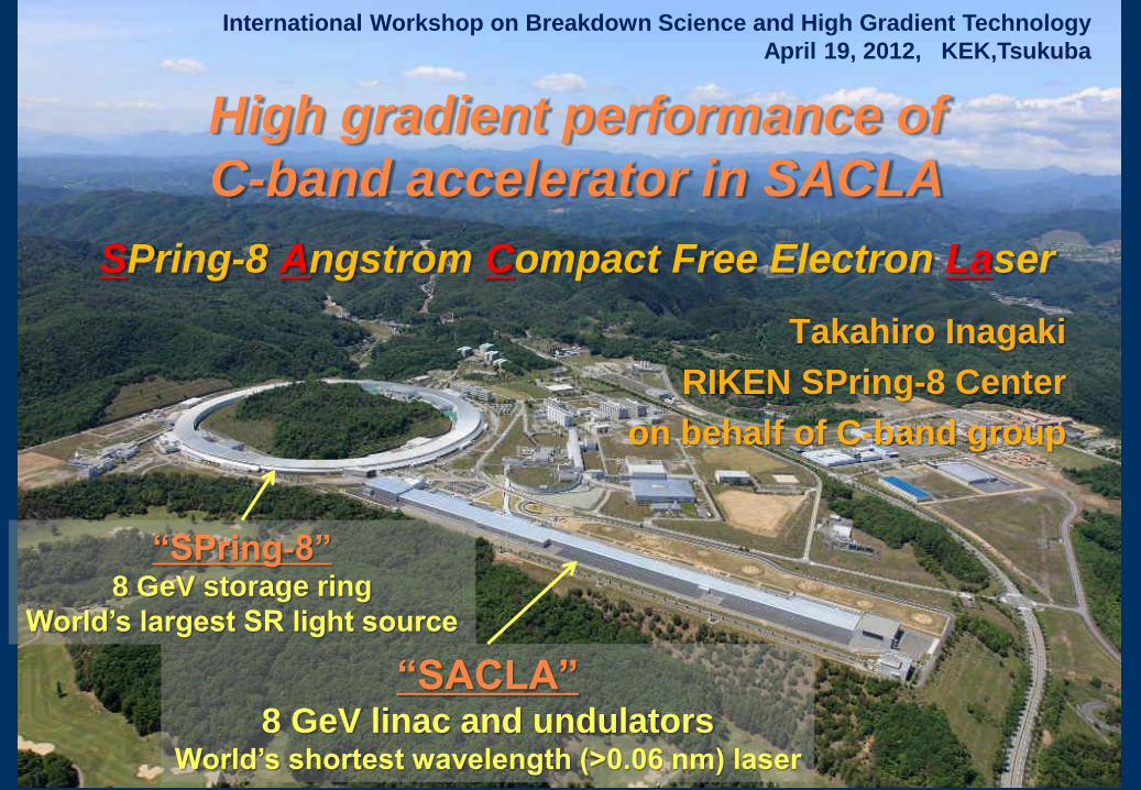
High gradient performance of
C-band accelerator in SACLA
SPring-8 Angstrom Compact Free Electron Laser
Takahiro Inagaki
RIKEN SPring-8 Center
on behalf of C-band group
International Workshop on Breakdown Science and High Gradient Technology
April 19, 2012, KEK,Tsukuba
“SACLA” 8 GeV linac and undulators
World’s shortest wavelength (>0.06 nm) laser
“SPring-8” 8 GeV storage ring
World’s largest SR light source
1) Overview of C-band accelerator system
2) Operational status
~ Accelerating gradient and trip rate ~
3) Dark current
4) Summary
Outline
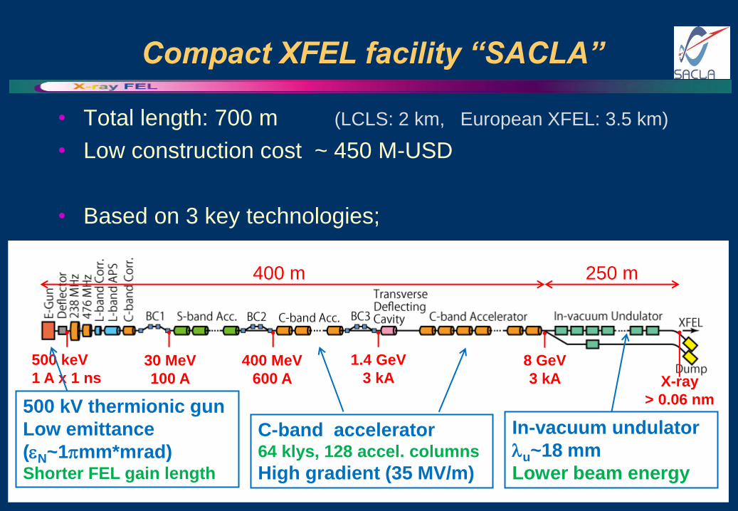
Compact XFEL facility “SACLA”
• Total length: 700 m (LCLS: 2 km, European XFEL: 3.5 km)
• Low construction cost ~ 450 M-USD
• Based on 3 key technologies;
C-band accelerator 64 klys, 128 accel. columns
High gradient (35 MV/m)
400 m 250 m
500 keV
1 A x 1 ns 30 MeV
100 A
400 MeV
600 A
1.4 GeV
3 kA 8 GeV
3 kA
500 kV thermionic gun
Low emittance
(N~1mm*mrad) Shorter FEL gain length
In-vacuum undulator
u~18 mm
Lower beam energy
X-ray
> 0.06 nm
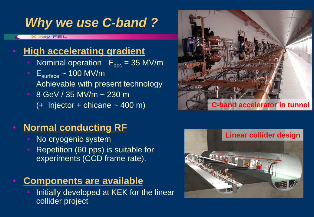
Why we use C-band ?
• High accelerating gradient • Nominal operation Eacc = 35 MV/m
• Esurface ~ 100 MV/m
Achievable with present technology
• 8 GeV / 35 MV/m ~ 230 m
(+ Injector + chicane ~ 400 m)
• Normal conducting RF • No cryogenic system
• Repetition (60 pps) is suitable for experiments (CCD frame rate).
• Components are available • Initially developed at KEK for the linear
collider project
C-band accelerator in tunnel
Linear collider design
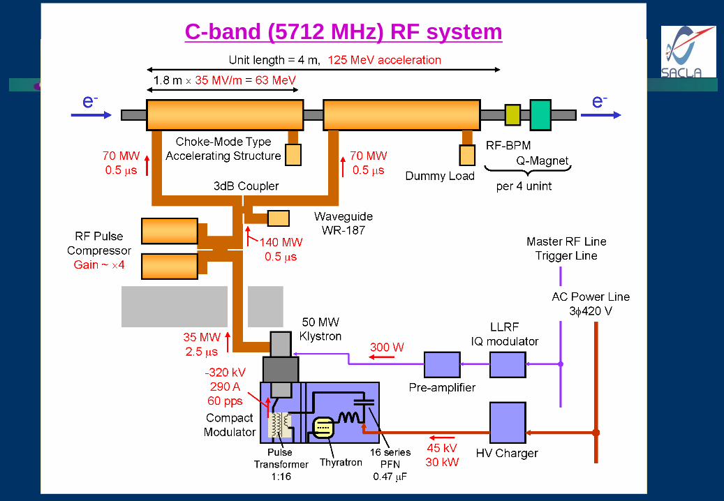
C-band (5712 MHz) RF system
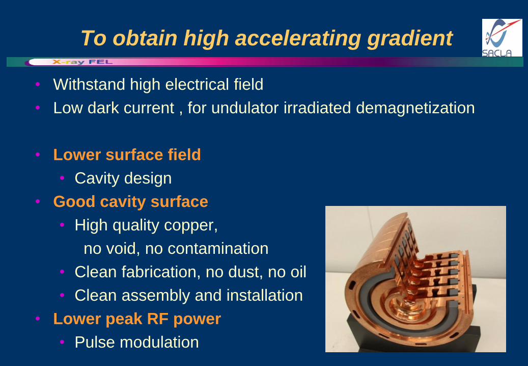
To obtain high accelerating gradient
• Withstand high electrical field
• Low dark current , for undulator irradiated demagnetization
• Lower surface field
• Cavity design
• Good cavity surface
• High quality copper,
no void, no contamination
• Clean fabrication, no dust, no oil
• Clean assembly and installation
• Lower peak RF power
• Pulse modulation
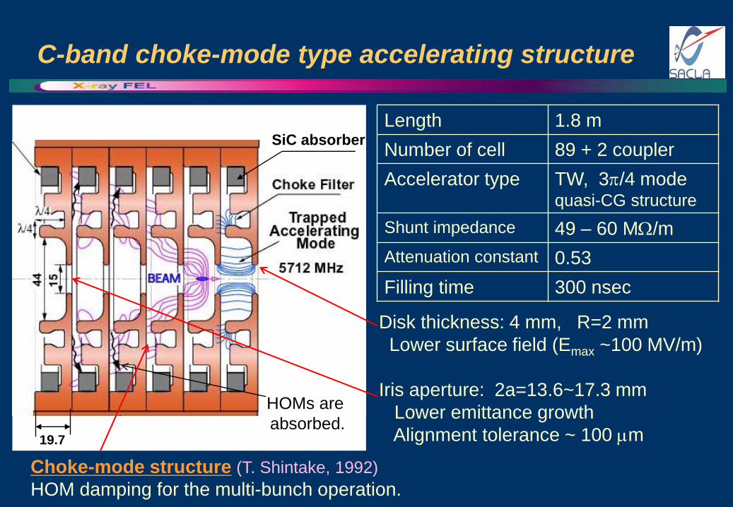
C-band choke-mode type accelerating structure
19.7
SiC absorber
Length 1.8 m
Number of cell 89 + 2 coupler
Accelerator type TW, 3/4 mode quasi-CG structure
Shunt impedance 49 – 60 M/m
Attenuation constant 0.53
Filling time 300 nsec
HOMs are
absorbed.
Disk thickness: 4 mm, R=2 mm
Lower surface field (Emax ~100 MV/m)
Iris aperture: 2a=13.6~17.3 mm
Lower emittance growth
Alignment tolerance ~ 100 m
Choke-mode structure (T. Shintake, 1992)
HOM damping for the multi-bunch operation.
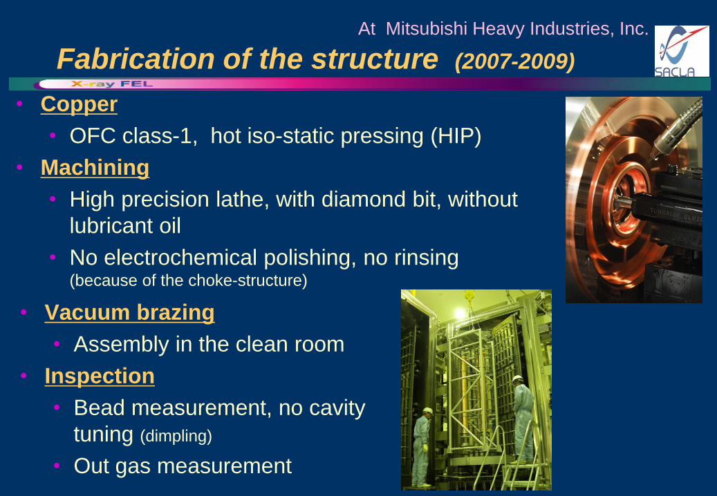
Fabrication of the structure (2007-2009)
• Copper
• OFC class-1, hot iso-static pressing (HIP)
• Machining
• High precision lathe, with diamond bit, without
lubricant oil
• No electrochemical polishing, no rinsing (because of the choke-structure)
At Mitsubishi Heavy Industries, Inc.
• Vacuum brazing
• Assembly in the clean room
• Inspection
• Bead measurement, no cavity
tuning (dimpling)
• Out gas measurement
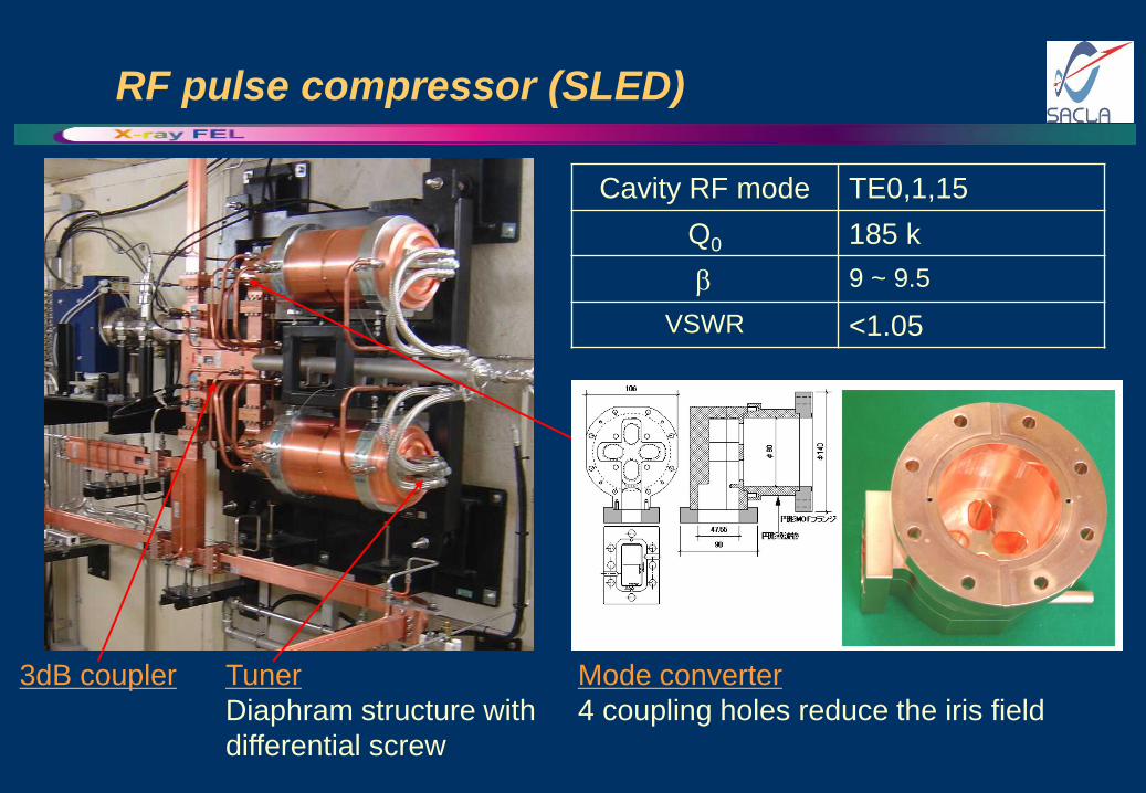
RF pulse compressor (SLED)
3dB coupler Mode converter
4 coupling holes reduce the iris field
Cavity RF mode TE0,1,15
Q0 185 k
9 ~ 9.5
VSWR <1.05
Tuner
Diaphram structure with
differential screw
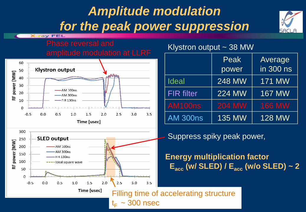
Amplitude modulation
for the peak power suppression
Peak
power
Average
in 300 ns
Ideal 248 MW 171 MW
FIR filter 224 MW 167 MW
AM100ns 204 MW 166 MW
AM 300ns 135 MW 128 MW
Phase reversal and
amplitude modulation at LLRF
Suppress spiky peak power,
Filling time of accelerating structure
tF ~ 300 nsec
Klystron output ~ 38 MW
Energy multiplication factor
Eacc (w/ SLED) / Eacc (w/o SLED) ~ 2
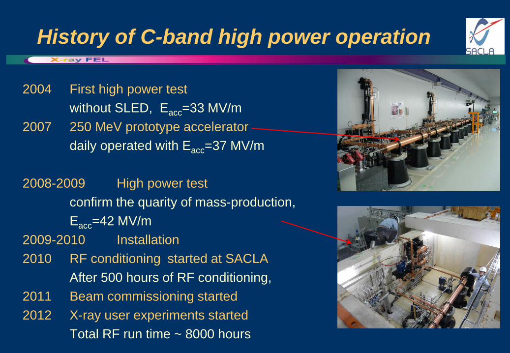
History of C-band high power operation
2004 First high power test
without SLED, Eacc=33 MV/m
2007 250 MeV prototype accelerator
daily operated with Eacc=37 MV/m
2008-2009 High power test
confirm the quarity of mass-production,
Eacc=42 MV/m
2009-2010 Installation
2010 RF conditioning started at SACLA
After 500 hours of RF conditioning,
2011 Beam commissioning started
2012 X-ray user experiments started
Total RF run time ~ 8000 hours
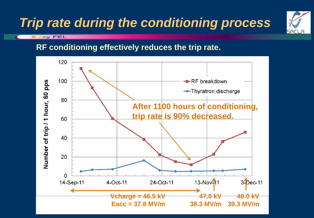
Trip rate during the conditioning process
Vcharge = 46.5 kV
Eacc = 37.8 MV/m
47.0 kV
38.3 MV/m
48.0 kV
39.3 MV/m
After 1100 hours of conditioning,
trip rate is 90% decreased.
RF conditioning effectively reduces the trip rate.
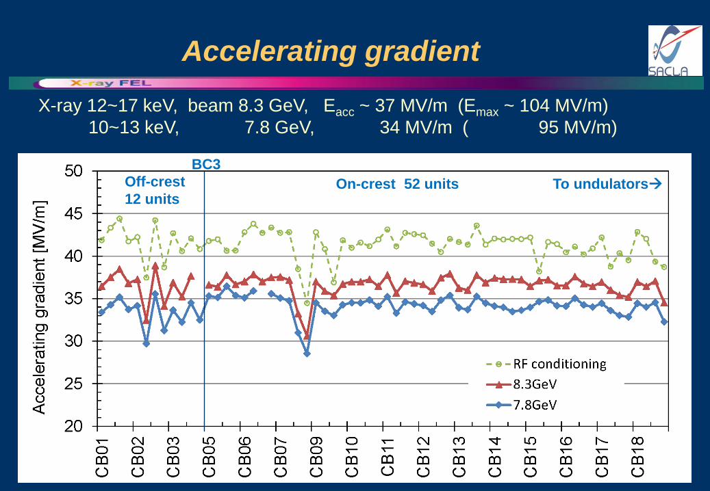
Accelerating gradient
Off-crest
12 units On-crest 52 units To undulators
BC3
X-ray 12~17 keV, beam 8.3 GeV, Eacc ~ 37 MV/m (Emax ~ 104 MV/m)
10~13 keV, 7.8 GeV, 34 MV/m ( 95 MV/m)
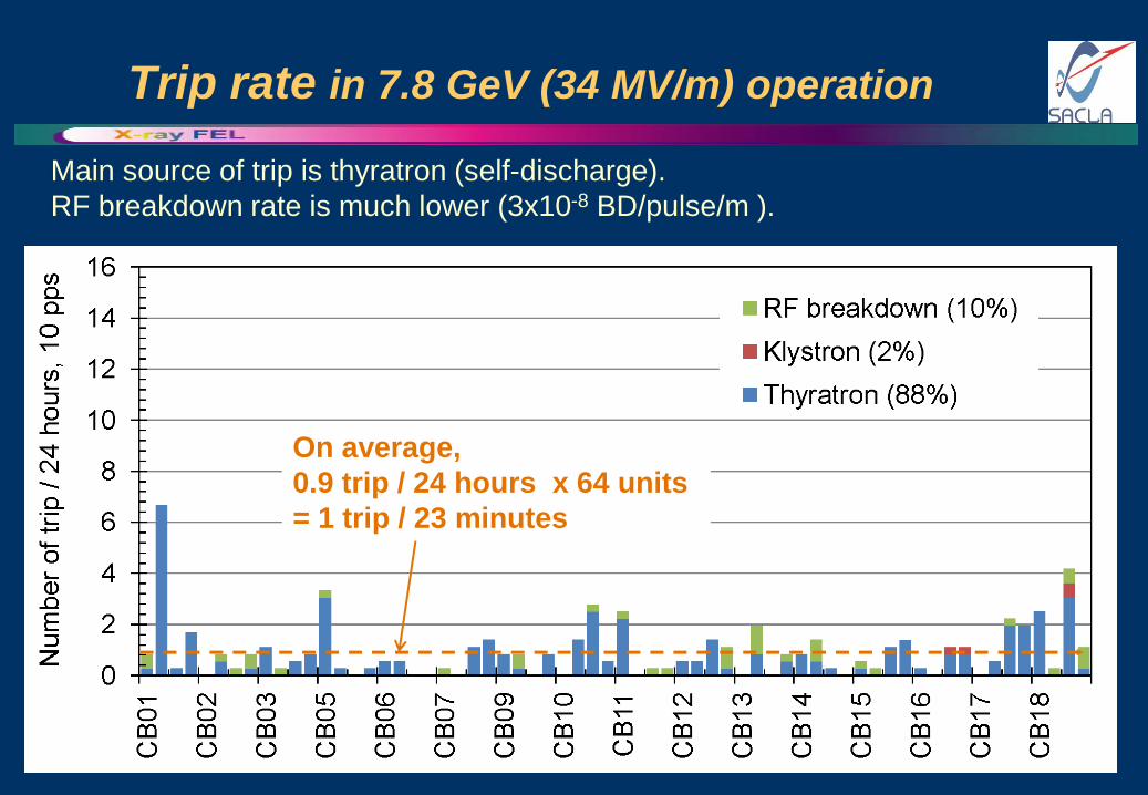
Trip rate in 7.8 GeV (34 MV/m) operation
Main source of trip is thyratron (self-discharge).
RF breakdown rate is much lower (3x10⁻⁸ BD/pulse/m ).
On average,
0.9 trip / 24 hours x 64 units
= 1 trip / 23 minutes
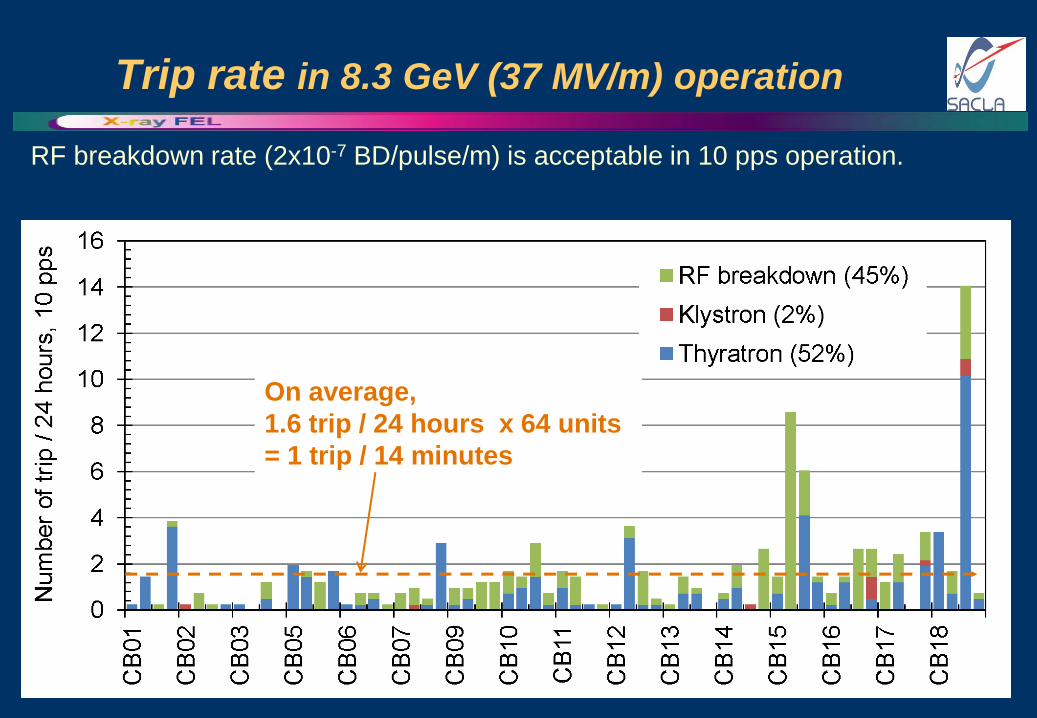
Trip rate in 8.3 GeV (37 MV/m) operation
RF breakdown rate (2x10⁻⁷ BD/pulse/m) is acceptable in 10 pps operation.
On average,
1.6 trip / 24 hours x 64 units
= 1 trip / 14 minutes
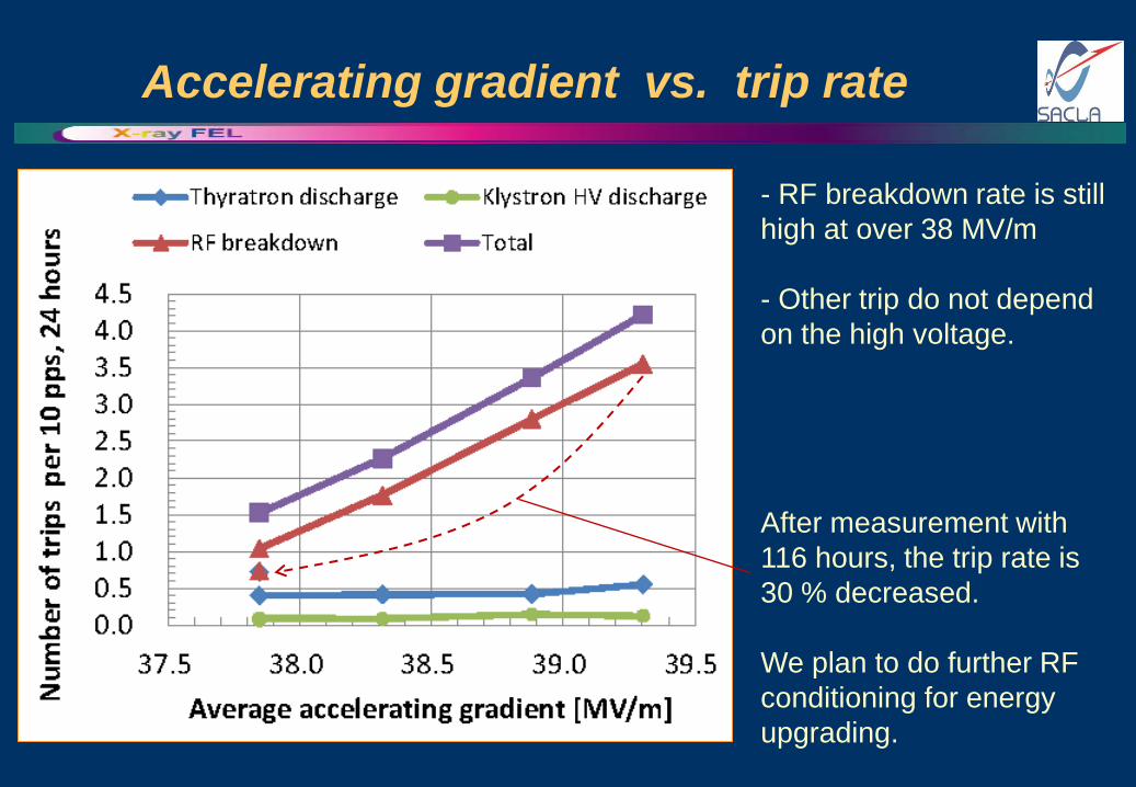
Accelerating gradient vs. trip rate
- RF breakdown rate is still
high at over 38 MV/m
- Other trip do not depend
on the high voltage.
After measurement with
116 hours, the trip rate is
30 % decreased.
We plan to do further RF
conditioning for energy
upgrading.
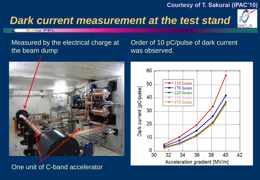
Dark current measurement at the test stand
Measured by the electrical charge at
the beam dump
Order of 10 pC/pulse of dark current
was observed.
Courtesy of T. Sakurai (IPAC’10)
One unit of C-band accelerator
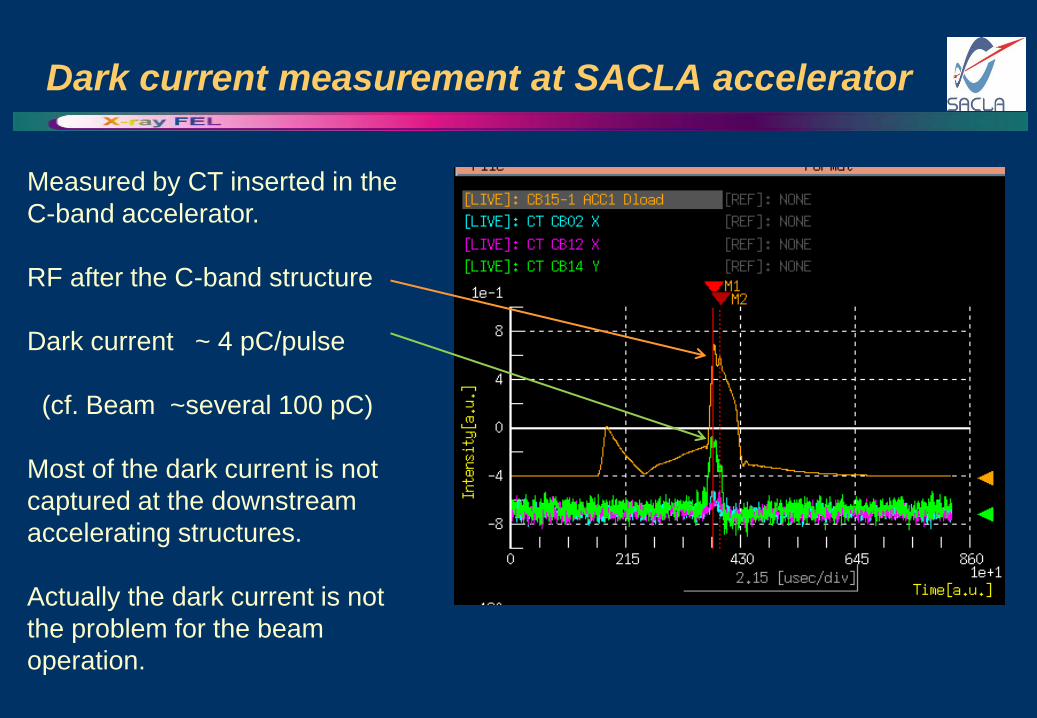
Dark current measurement at SACLA accelerator
Measured by CT inserted in the
C-band accelerator.
RF after the C-band structure
Dark current ~ 4 pC/pulse
(cf. Beam ~several 100 pC)
Most of the dark current is not
captured at the downstream
accelerating structures.
Actually the dark current is not
the problem for the beam
operation.
Summary and prospect
• Since 2011, 64 units of C-band accelerator has been well
operated for X-ray FEL, to accelerate beam up to 8.3 GeV, with
an average gradient of 37 MV/m.
• RF breakdown rate is low enough for 8 GeV (~35 MV/m) beam
operation.
• For 8.3 GeV (37 MV/m), the trip rate is acceptable for 10 pps
operation, although we plan to decrease the trip by further RF
conditioning.
• We plan to increase the repetition 10 pps 60 pps, after fixing
other problems (thyratron, power supply,…).
• Dark current is actually low enough and no problem.
Spare slides

8 GeV XFEL Machine Layout
Injector S-band 4 units
C-band (48 off-crest) 12 units
C-band (crest) 52 units
Undulators
30 MeV
100 A
500 keV
1 A x 1 ns
1.4 GeV
3 kA
400 MeV
600 A
Bunch compression
Acceleration
X-ray Laser
> 0.06 nm
64 klys, 128 accel. columns
8 GeV
3 kA
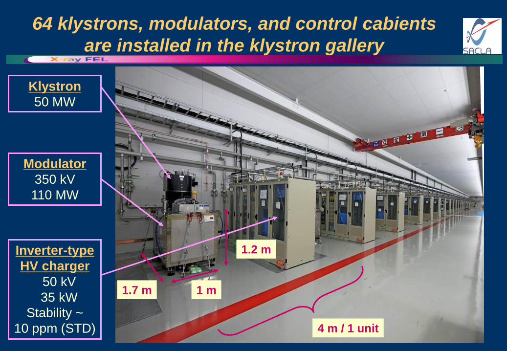
64 klystrons, modulators, and control cabients
are installed in the klystron gallery
4 m / 1 unit
Klystron
50 MW
Modulator
350 kV
110 MW
Inverter-type
HV charger
50 kV
35 kW
Stability ~
10 ppm (STD)
1 m
1.2 m
1.7 m
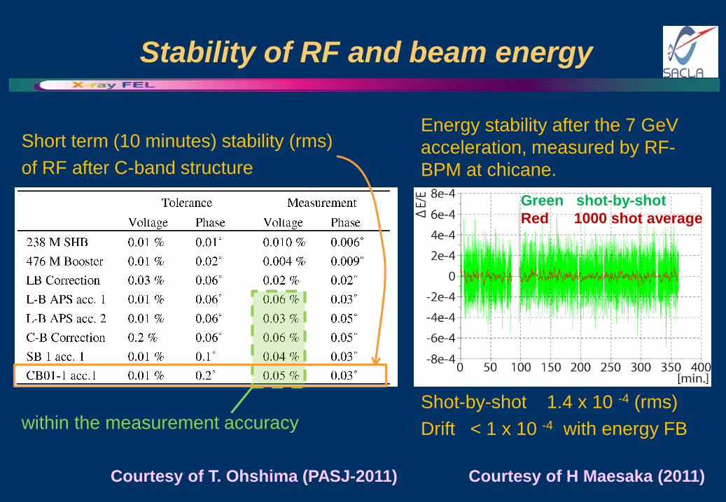
Stability of RF and beam energy
Short term (10 minutes) stability (rms)
of RF after C-band structure
Courtesy of T. Ohshima (PASJ-2011)
within the measurement accuracy
Energy stability after the 7 GeV
acceleration, measured by RF-
BPM at chicane.
Courtesy of H Maesaka (2011)
Shot-by-shot 1.4 x 10 -4 (rms)
Drift < 1 x 10 -4 with energy FB
Green shot-by-shot
Red 1000 shot average