Embed Size (px)
Citation preview

HV1000 PULSER OPERATION MANUAL
SERIAL NUMBER: ------
DATE: ---------
Directed Energy, Inc. 2301 Research Blvd., Ste. 105 Fort Collins, Colorado 80526
970/493-1901 FAX 970/493-1903

DEI HVlOOO PULSER REV B
r-
i I
TABLE OF CONTENTS
1. 0 GENERAL DESCRIPTION ................................ 3
2. 0 SPECIFICATIONS ..................................... 4 2 .1 Maximum Duty Cycles ................................ 5 2. 2 Pulse Droop ........................................ 5
3 . 0 SAFETY ............................................. 6 3.1 Operating Safety Summary ........................... 6 3.2 Servicing Safety Summary ........................... 7
4.0 OPERATING CONSIDERATIONS ........................... 8 4.1 Output ............................................. 8 4.2 Pulse Risetime and Falltime ........................ 8 4. 3 Impedance Matching ................................. 8 4 . 4 Trigger Input ...................................... 8 4. 5 High Voltage Input ................................. 9 4. 6 Maximum Duty Cycle ................................. 9
5.0 PREPARATION FOR USE ............................... 10 5 .1 General ........................................... 10 5.2 Initial Inspection ................................ 10 5. 3 Electrical Installation ........................... 10 5.4 Mechanical Installation ........................... 10 5.5 Electrical Check .................................. 10
6.0 OPERATING INSTRUCTIONS ............................ 12 6 . 1 Power- Up Procedures ............................... 12 6.2 Power-Down Procedures ............................. 12
7 . 0 EXAMPLE WAVEFORMS ................................. 14 7 .1 50 Ohm Resistive Load ............................. 14 7.2 Inductive Load (Step-Up Transformer) .............. 15 7 .3 Capacitive Load ................................... 15 7. 4 Current Source .................................... 16
8 . 0 TROUBLESHOOTING ................................... 1 7 8.1 Troubleshooting Procedures ........................ 17 8. 2 Factory Service ................................... 18
9 . 0 SYSTEM FAILURE MODES .............................. 19 9.1 Over-Current Failure .............................. 19 9. 2 Over-Voltage Failure .............................. 19
10. 0 WARRANTY ......................................... 20
11.0 APPENDIX A - Schematics .......................... 21
1
DEI HVl000 PULSER
********** WARNING **********
SAFE OPERATING PROCEDURES AND PROPER USE OF THE EQUIPMENT ARE THE RESPONSIBILITY OF THE USER OF THIS SYSTEM.
Directed Energy, Inc (DEI) provides information on its products and associated hazards, but it assumes no responsibility for the after-sale operation and safety practices.
ALL PERSONNEL WHO WORK WITH OR ARE EXPOSED TO THIS EQUIPMENT MUST TAKE PRECAUTIONS TO PROTECT THEMSELVES AGAINST POSSIBLE SERIOUS AND/OR FATAL BODILY INJURY. DO NOT PERFORM INTERNAL REPAIR OR ADJUSTMENTS UNLESS ANOTHER PERSON CAPABLE OF RENDERING FIRST AID AND RESUSCITATION IS PRESENT.
2
REV B

DEI HVlOOO PULSER REV B
1.0 GENERAL DESCRIPI'ION
The HVlOOO Pulser is a high voltage pulse generator designed to be operated into a load impedance of 50 ohms. The HVlOOO is designed as an instrument for lab experiments, calibration, component testing, beam steering, gating PMTs and MCPs, and other applications that require very fast and clean high speed pulses, or incorporated into an OEM system.
The HVlOOO utilizes a patented state-of-the-art high-speed power MOSFET as the high voltage switch, incorporated into a low impedance configuration featuring a multi-layer stripline-style output bus.
The HVlOOO requires an external high voltage DC supply (950V maximum), and an input trigger. The unit is available in either positive or negative polarities. The polarity of the DC power supply must be the same as the polarity of the HVlOOO (i.e. a positive-polarity HVlOOO requires a positive polarity DC power supply; a negative-polarity HVlOOO requires a negative polarity DC power supply).
3
DEI HVl000 PULSER REV B
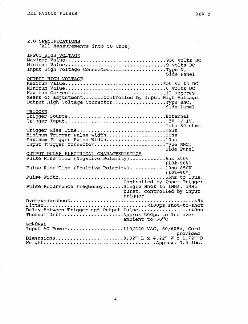
2.0 SPECIFICATIONS (All Measurements into 50 Ohms)
INPUT HIGH VOLTAGE Maximum Value .............•.......•.......•.... 950 volts DC Minimum Value .••.•.........................•.•. 0 volts DC Input High Voltage Connector ...........•..•.... Type N,
Side Panel OUTPUT HIGH VOLTAGE Maximum Value ........•.........•..•.••••...... 850 volts DC Minimum Value ..........•....•............•..... 0 volts DC Maximum Current ....•........................... 1 7 amperes Means of adjustment .....•. Controlled by Input High Voltage Output High Voltage Connector .......•..•....... Type BNC,
Side Panel TRIGGER Trigger Source ...•....••...................•... External Trigger Input •............•.......•..•......... +5V +/-lV,
Into 50 ohms Trigger Rise Time .......•.••............•...... <6ns Minimum Trigger Pulse Width .......•..•..••..... 55ns Maximum Trigger Pulse Width ....•........•..•... l0us Input Trigger Connector ...•.......•......•.•... Type BNC,
Side Panel OUTPUT PULSE ELECTRICAL CHARACTERISTICS Pulse Rise Time (Negative Polarity) ..•..••..... 6ns 850V
(10%-90%) Pulse Rise Time (Positive Polarity) ..•.••.....• l0ns 850V
(10%-90%) Pulse Width .......•..•....•••..••..•.•...••••.. 55ns to lOus,
Controlled by Input Trigger Pulse Recurrence Frequency •.••..• Single Shot to 1MHz, 5MHz
burst, controlled by input trigger
Over /undershoot . ......................................... <5% Jitter ...•.....•••.....•.•..••.....••...• <lO0ps shot-to-shot Delay Between Trigger and Output Pulse •.•.••....•...... <40ns Thermal Drift ..•.••...•.•••..•.•. Approx 500ps to lns over
ambient to 5o 0 c GENERAL Input AC Power ••.•...•......••.•. 110/220 VAC, 50/60Hz, Cord
provided Dimensions .•.••..••.....••...•... 8.32" L x 4.22" W x 1.72" D Weight. . . . . . . . . . . . . . . . . . . . . . . . . . . . . . . . . . . . . Approx. 3. 5 lbs.
4

DEI HVlOO0 PULSER
2.1
2.2
Maximum Duty Cycles All measurements into 50 ohms.
VIN IoUT PPEAK
950V 17.0A 14.50KW 525V 9.5A 4.50KW 105V 2.0A 0.20KW
Pulse Droog All measurements into 50 ohms.
VIN
950V 950V 525V 525V 105V 105V
PULSE WIDTH
l.0us 10.ous
1.ous 10.ous
1.ous 10.0us
5
DUTY CYCLE (MAX)
1% 4%
10%
PERCENTAGE DROOP
3.0% 24.0%
1.5% 16.0% <0.5%
7.0%
REV B

DEI HVl000 PULSER REV B
3.0 SAFETY
The high voltage nature of this device dictates the use of caution when operating or servicing this equipment. The following is a summary of general safety precautions that must be observed during all phases of operation and repair of the HVl000 Pulser.
3.1 Operating Safety Summary
The safety information contained in this summary is for both operating and servicing personnel. Specific warnings may be found throughout this manual, but may not appear in this summary.
3.1.1 Power Source
The HVl000 is designed to operate from a power source that will not apply more than 220 volts between the supply conductors or between either supply conductor and ground. A protective grounding connection by way of the grounding conductor in the AC power cord is essential.
3.1.2 Grounding
The HVl000 is grounded through the grounding conductor of the AC power cord. To avoid electrical shock, plug the HVlOOO into a properly wired receptacle before making connection to any input or output connectors. Use only a power cord that is in good condition.
3.1.3 Cover Removal
To avoid personal injury, do not remove the cover. Do not operate the HVlOOO while the cover is removed. The cover does not contain a safety interlock!
3.1.4 General Operating Precautions
Do not remove the input or output cables while the pulser is in operation. Never short-circuit the high voltage output of the pulse generator. Failure to observe these precautions can result in potential electric shock to personnel, arcing, and damage to the connectors and system.
The top cover of the pulse generator is not safety interlocked. Extreme caution should be exercised when removing the cover.
6

DEI HVlOOO PULSER REV B
Any pulsed power system is capable of random triggering via transients. Therefore when the pulse generator is turned on, or high voltage is present in the chassis, assume it is possible to get a pulse on the output connector.
3.2 Servicing Safety Summary
The HVlOOO contains dangerous voltages and stored energy. DEI strongly recommends that all repairs and adjustments be performed by factory qualified personnel. DEI will not be responsible for personal injury or damage to the pulser that occurs during repair by any party other than the factory.
3.2.1 Servicing Procedure
Do not perform internal repair or adjustments unless another person capable of rendering first aid and resuscitation is present.
3.2.2 Internal Energy Storage
The HVlOOO contains capacitors that are used as energy storage elements. When charged, these capacitors contain in excess of 1.5 joules of stored energy. This is sufficient energy to cause serious injury. Assure that the AC power cord is disconnected from the pulser, and that the capacitor bank is fully discharged and a shorting strap installed before any repairs or adjustments are attempted. Verify with a voltmeter that all circuits are de-energized before servicing. The voltmeter used to make these measurements must be certified for use at lOOOVDC and 220VAC or greater. Dangerous voltages, floating ground planes and energy storage exist at several locations in the HVlOOO. Touching connections and/or components could result in serious injury.
7

' DEI HVl000 PULSER
4.0 OPERATING CONSIDERATIONS
4.1 Output
REV B
The HVl000 is designed to operate into a load whose characteristic impedance is 50 ohms. An unterminated or improperly terminated output will cause excessive aberrations on the output waveform and could possibly damage the pulser. To ensure this does not occur, observe the following precautions: - Use good quality 50 ohm coaxial cable and connectors; - Make all external connections tight and as short as
possible; - Use good quality attenuators and/or loads. If using an
attenuator, DEI recommends the Weinschel Engineering model 45-40-33. Small attenuators will not work correctly and can be harmed by the HVl000;
- Use terminators or impedance-matching devices to avoid reflections;
- Ensure that all external cables and hardware have adequate voltage and power ratings;
- Be extremely careful not to short the output of the pulser to ground, as this can cause damage to the pulser.
The HVl000 can be used to drive capacitive, inductive and resistive loads other than 50 ohms. Please consult the factory for further applications information.
4.2 Pulse Risetime and Falltime The physical and electrical characteristics of the cable transmitting the pulse determine the characteristic impedance, velocity of propagation and the amount of signal loss. Several feet of cable can attenuate high frequency information in a pulse with a fast rise time. It is therefore important to keep these cables as short as is practical. For optimum performance, DEI recommends interconnecting cable lengths of 8 11 or less. When signal comparison measurements or time difference determinations are made, the two signals from the test device should travel through coaxial cables with identical less and time delay characteristics.
4.3 Impedance Matching If a pulse travels down a transmission line and encounters a mismatch, a reflection is generated and sent back along the line to the source. The amplitude and polarity of the reflection are determined by the impedance mismatch. If the reflected signal returns before the output pulse ends, it adds or subtracts from the amplitude of the pulse. This will distort the pulse shape and amplitude.
4.4 Trigger Input An input trigger of +5V +/-lV into 50 ohms with a risetime
8

DEI HVl000 PULSER REV B
of <6ns is required to gate on the HVl000. Departure from these values can result in a loss of performance. These trigger requirements are met by any high quality low voltage pulse generator. The trigger should be set to +5V +/-lV into 50 ohms before the trigger cable is attached to the HVl000 trigger input. The input trigger is transformer-coupled into a DS0026 CMOS Clock Driver which does not appear resistive to the input pulse generator. For this reason, the input trigger amplitude should be set using a 50 ohm load (e.g. a 50 ohm scope input) before connecting it to the HVl000. If the trigger input is greater than +5V into 50 ohms, pulse stretching can occur.
4.5 High Voltage Input The HVl000 is rated at a maximum input voltage of 950VDC. Proper precautions should be taken by the user to ensure that the maximum voltage is not exceeded. The polarity of the DC power supply must be the same as the polarity of the HVl000 (i.e. a positive-polarity HVl000 requires a positive polarity DC power supply; a negative-polarity HVl000 requires a negative polarity DC power supply).
4.6 Maximum Duty Cycle The case of the HVl000 (specifically the bottom panel) is used as the heat sink for the power circuitry. Therefore the case can get hot! Use caution when handling the HVl000 after operation. The duty cycle percentages shown in TABLE 2.1 are limited by the cooling capabilities of the HVl000. Higher duty cycles can be obtained by forced air cooling of the enclosure, or for very high power applications (>lKw), bolting the HVl000 to a water or air cooled heat sink.
9

DEI HVl000 PULSER
5.0 PREPARATION FOR USE
5.1 General
REV B
After unpacking, initial inspection and preliminary electrical check procedures should be performed to assure that the unit is in good working order. If it is determined that the unit is damaged, the carrier should be notified immediately. Repair problems should be directed to the service department, Directed Energy, Inc. (DEI), Fort Collins, Colorado. Telephone: (303) 493-1901.
5.2 Initial Inspection 1. Inspect unit for exterior mechanical damage. 2. Inspect power input cord and input power module for
obvious signs of damage. 3. Remove top cover retaining screws. Inspect components
and printed circuit board for damage.
5.3 Electrical Installation Standard units are shipped ready for use with a nominal 110 VAC input. The unit can be configured for 220VAC input from the factory.
5.3.1 Input Power Cord The input power cord terminates externally in a three-prong polarized plug. The unit chassis is wired to the plug through the line cord, and therefore, the insertion of the plug into a compatible receptacle, hooked up to a grounded input, will automatically ground the unit. The unit should not be operated without a grounded AC input!
5.4 Mechanical Installation As received, the unit is ready for bench use. If necessary, the unit can be bolted to an external heat sink for additional cooling (see Section 4.6 above) using the mounting flanges.
The HVl000 is extremely rugged, and can be mounted to other equipment, hardware or benches using the mounting flanges. Physical orientation is not critical.
5.5 Electrical Check Before proceeding, please review the precautions in Section 3.
5.5.1 Power-Up The unit should be powered up using the following procedures: 1. Ensure that the high voltage power supply is turned
off, and all controls set to zero volts.
10
DEI HVl000 PULSER REV B
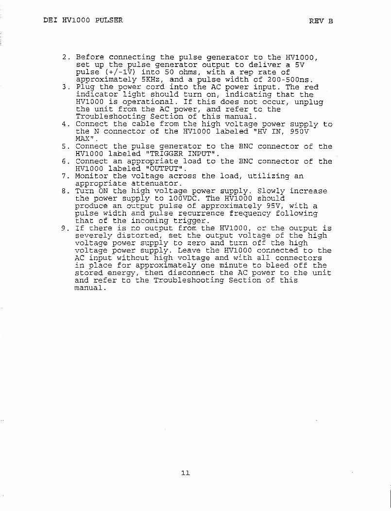
2. Before connecting the pulse generator to the HVl000, set up the pulse generator output to deliver a 5V pulse (+/-lV) into 50 ohms, with a rep rate of approximately 5KHz, and a pulse width of 200-S00ns.
3. Plug the power cord into the AC power input. The red indicator light should turn on, indicating that the HVl000 is operational. If this does not occur, unplug the unit from the AC power, and refer to the Troubleshooting Section of this manual.
4. Connect the cable from the high voltage power supply to the N connector of the HVl000 labeled "HV IN, 950V MAX".
5. Connect the pulse generator to the BNC connector of the HVl000 labeled "TRIGGER INPUT".
6. Connect an appropriate load to the BNC connector of the HVl000 labeled "OUTPUT".
7. Monitor the voltage across the load, utilizing an appropriate attenuator.
8. Turn ON the high voltage power supply. Slowly increase the power supply to l00VDC. The HVl000 should produce an output pulse of approximately 95V, with a pulse width and pulse recurrence frequency following that of the incoming trigger.
9. If there is no output from the HVl000, or the output is severely distorted, set the output voltage of the high voltage power supply to zero and turn off the high voltage power supply. Leave the HVl000 connected to the AC input without high voltage and with all connectors in place for approximately one minute to bleed off the stored energy, then disconnect the AC power to the unit and refer to the Troubleshooting Section of this manual.
11
DEI HVlOOO PULSER REV B
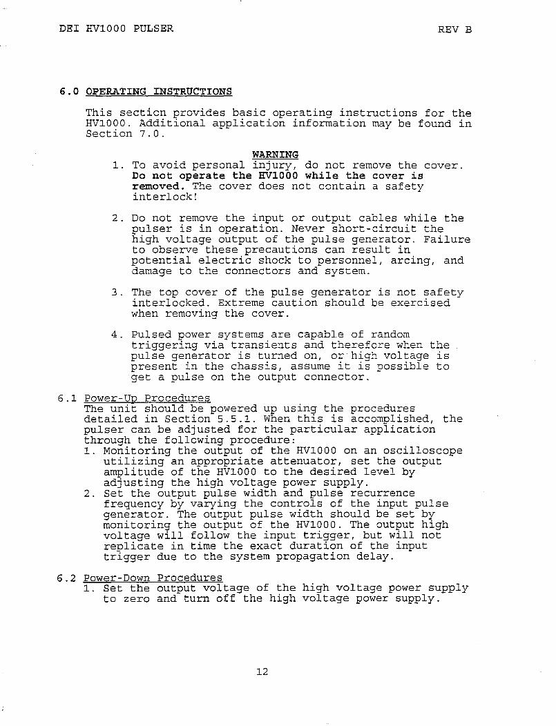
6.0 OPERATING INSTRUCTIONS
This section provides basic operating instructions for the HVlOOO. Additional application information may be found in Section 7.0.
WARNING 1. To avoid personal injury, do not remove the cover.
Do not operate the HVlOOO while the cover is removed. The cover does not contain a safety interlock!
2. Do not remove the input or output cables while the pulser is in operation. Never short-circuit the high voltage output of the pulse generator. Failure to observe these precautions can result in potential electric shock to personnel, arcing, and damage to the connectors and system.
3. The top cover of the pulse generator is not safety interlocked. Extreme caution should be exercised when removing the cover.
4. Pulsed power systems are capable of random triggering via transients and therefore when the pulse generator is turned on, or high voltage is present in the chassis, assume it is possible to get a pulse on the output connector.
6.1 Power-Up Procedures The unit should be powered up using the procedures detailed in Section 5.5.1. When this is accomplished, the pulser can be adjusted for the particular application through the following procedure: 1. Monitoring the output of the HVlOOO on an oscilloscope
utilizing an appropriate attenuator, set the output amplitude of the HVlOOO to the desired level by adjusting the high voltage power supply.
2. Set the output pulse width and pulse recurrence frequency by varying the controls of the input pulse generator. The output pulse width should be set by monitoring the output of the HVlOOO. The output high voltage will follow the input trigger, but will not replicate in time the exact duration of the input trigger due to the system propagation delay.
6.2 Power-Down Procedures 1. Set the output voltage of the high voltage power supply
to zero and turn off the high voltage power supply.
12

DEI HVlOOO PULSER REV B
2 Leave the HVlOOO connected to the AC input without high voltage and with all connectors in place for approximately one minute to bleed off the stored energy.
3. Disconnect the AC power to the unit.
13

DEI HVlO00 PULSER REV B
7.0 EXAMPLE WAVEFORMS
7.1 50 Ohm Resistive Load
Input Voltage=l0SV, Pulse Width=S00ns, Pulse Recurrence Frequency=lMHz, Load=50 ohms:
Input Voltage=950V, Pulse Width=lO0ns, Pulse Recurrence Frequency=4.5MHz (Burst Mode), Load=50 ohms:
14

DEI HVl000 PULSER REV B
7.2 Inductive Load (Step-Up Transformer)
Input Voltage=950V, Pulse Width=200ns, Pulse Recurrence Frequency=500Hz, Oscilloscope Scale=l000V/DIV, Load=l000 ohm in secondary:
7.3 Capacitive Load
Input Voltage=150V, Oscilloscope Scale=SA/DIV, Load=0.lmF, lKV Ceramic Capacitor, Traces show Voltage and Current:
15

DEI HVl000 PULSER
7.4 Current Source
Input Voltage=575V, Pulse Width=400ns, Oscilloscope Scale=l0A/DIV, Load=5 ohms:
16
REV B

DEI HVl000 PULSER REV B
8.0 TROUBLESHOOTING
WARNING
The HVl000 contains capacitors that are used as energy storage elements. When charged, these capacitors contain in excess of 1.5 joules of stored energy. This is sufficient energy to cause serious injury. Assure that the AC power cord is disconnected from the pulser, and that the capacitor bank is fully discharged and a shorting strap installed before any repairs or adjustments are attempted. Verify with a voltmeter that all circuits are de-energized before servicing. The voltmeter used to make these measurements must be certified for use at l000VDC and 220VAC or greater. Dangerous voltages, floating ground planes and energy storage exist at several locations in the HVl000. Touching connections or components could result in serious injury.
8.1 Troubleshooting Procedures Before attempting to service or troubleshoot the HVl000, review the servicing safety summary in Section 3.0.
The power MOSFET utilized in the HVl000 is mounted underneath the printed circuit board, and utilizes the case as a heat sink. In the unlikely event that the MOSFET need be replaced, it is highly recommended that the unit be returned to the factory for servicing.
The table below summarizes potential problems and their solutions. If these recommendations do not resolve the problem, DEI customer service can be contacted for further assistance.
SYMPTOM 1. Red LED does not
illuminate
2. No output pulse.
17
SOLUTIONS -AC power not plugged in. -Fuse(s) are blown. See fuse
replacement instructions in Section 8.1.1.
-No input trigger. -Input trigger voltage too
low. -Input trigger pulse width
too short. Increase width. -Input trigger frequency too high. Reduce frequency.
-No input high voltage. Check HV supply and connections.
-Output not connected correctly. Check all cables and connections.

DEI HVl000 PULSER
8.1.1 Fuses
REV B
-Pulser is damaged. Contact DEI customer service.
To avoid fire hazard or damage to the pulser, use only 3A fast blow fuses (Littlefuse #312003 or equivalent). Fuse replacement should be performed by qualified personnel only. Assure that the AC power cord is disconnected from the pulser, and that the capacitor bank is fully discharged and a shorting strap installed before fuse replacement is attempted. Verify with a voltmeter that all circuits are de-energized before servicing. The voltmeter used to make these measurements must be certified for use at l000VDC and 220VAC or greater.
The fuses are located in the corner of the printed circuit board, adjacent to the power entry module.
8.2 Factory Service If the procedures above fail to resolve an operational problem, please contact the factory for further assistance:
DIRECTED ENERGY, INC. 2301 RESEARCH BLVD SUITE 105 FORT COLLINS, CO 80526 (303) 493-1901 FAX (303) 493-1903
18

DEI HVlOOO PULSER REV B
9.0 SYSTEM FAILURE MODES
The HVlOOO pulse generator is capable of generating large amplitude current pulses with very fast rise and fall times. There is no over-current or over-voltage protection circuitry, and it is the user's responsibility to assure that the interconnect cables and load do not create transients, over-current or over-voltage conditions that could damage the pulse generator. FAILURE TO DO SO VOIDS THE WARRANTY.
9.1 Over-Current Failure When the output is shorted, the HVlOOO can deliver up to 200A of current (depending on cabling, HV power supply setting, etc.). A current pulse of this magnitude is far in excess of the generator's maximum specification, and may cause damage to the pulse generator, load and/or associated cabling.
The output can be shorted by allowing the two output leads to touch each other, the "hot" lead to contact ground, load arcing, or a shorted load.
9.2 Over-Voltaoe Failure One may incorrectly assume that the voltage across the MOSFET switching device could never exceed the 950V maximum input high. voltage. It is possible to create voltages in excess of 950V by driving an open cable or by generating L di/dt spikes.
From transmission line theory it is known that a voltage pulse launched onto an open cable will cause the voltage to reflect back down the cable and double in amplitude. This voltage doubling will over-voltage the MOSFET and lead to pulse generator failure. Turning on the pulse generator with the load disconnected or opening the load while the pulse generator is operating may cause it to fail due to this voltage doubling effect.
L di/dt spikes are created when current flowing through an inductor is interrupted (i.e. current is turned off). The amplitude of the resultant voltage spike is defined by the formula:
V = L di/dt,
where Lis the circuit inductance, di is the current value at turn off and dt is the time it takes for the current to get to zero (i.e. fall time). By monitoring the voltage output of the pulse generator, the user can measure L di/dt voltage spikes. With this measurement, the user can determine the actual voltage across the MOSFET switching device, with the formula:
19

DEI HVl000 PULSER REV B
where
Vmax = [L di/dt] + Vsupply
peak of the negative-going spike; panel meter voltage;
L di/dt = Vsupply = Vmax = 950 volts.
Any time the test setup (e.g. interconnect cables and/or load resistance) is changed, it will be necessary to again verify that Vmax is no greater than 950 volts.
10 . 0 WARRANTY
Directed Energy, Inc. (DEI) warrants all parts of equipment of its manufacture to be free from defects caused by faulty material or poor workmanship. Directed Energy, Inc's obligation is limited under the warranty to repair or replacement of products in kind. Returns must be accompanied by a Directed Energy, Inc. return authorization number and conform to standard conditions for adjustment. The aforesaid warranty shall expire twelve (12) months following the day of shipment from Directed Energy, Inc's plant~ The foregoing states the entire warranty extended by Directed Energy, Inc. No other warranty, expressed or implied, is made and, specifically, Directed Energy, Inc. makes no warranty of merchantability or fitness for any purpose. In no case shall Directed Energy, Inc. be liable for any special or consequential damages. Authorization must be obtained prior to return of defective items.
20

DEI HVlOOO PULSER REV B
APPENDIX A
SCHEMATICS
21

REVI EC DESCRIPTION DATE I BY ICHK(:1 ENG
SIGNAL TRANSFORMER PART # 14A-2.5-36
01 I - I ORIGINAL ISSUE
A2 COMPONENT UPDATES
A3 HVX UPDATES, NEW TITLE 3L 21}911 RS I GK
7 /26J91I RS I GK
CONN. Tl FLOATING + 15V POWER SUPPLY 7
I I I
H
N
G
1N4002 (4)
0 100V@1A
i-- - --C13
(--
C1 __L C2 J 1000uf J 0.47uf 35V 50V
1 1
-- -- --
VRl LM342-1
-
7
C3 T O.luf 'Q 50V
1 '
L 7 _J
3019 POT CORE 3C8 OR 387
R3 0.01 -- TI 5K 4W • •• __j 1 OK!l/2 2W
1 GATE DRIVE
3.3 C14 3.3
C7 C11
I I l I I I I
L R10 51
100
D~-~8 c 5 0.01
.01 1 1
/
Ul DS0026
0.01
C15
0.01
C16
0.01 1
R4 ~ ~
l~ I ~ 3.3
nr I I
3.3
-- -- -- -- -- -- --L2 TRIGGER
"9 c12
0.47
1
01 IRFD9120
I R13
02 , 680
IRFD110 D5 I 1 N4744
I
J 7o = EARTH GROUND
_ D6 Rl 1 K T2
I D7
E R12 J
'7 l = FLOATING GROUND
• = OFF-CARD
•• = HVX ONLY
3019 1811 'Q L ~
POT CORE 3CB OR 3~ __ __ POT CORE 3C8 ::J NOTICE
THIS DOCUMENT CONTAINS PROPRlnARY INFORMATION OF DIRECTED ENERGY, INC. AND JS NOT TO BE TRANSMITTED, USED OR DISCLOSED TO ANYONE OR PARTY. OR TO BE USED AS THE BASIS fOR THE MANUFACTURE OR SALE OF ANY ARTICLE WITHOUT THE WRITTEN PERMISSION or DIRECTED ENERGY, INC.
!HIGH VOLTAGESWITCH
5.1M 2W •
GATE -<>--
SG2
I
0
7 I
3019 POT CORE l 3C8 OR 387
20 EA O.Oluf
I I
28 EA I 0.1uf
I
0
I L v' 1
OUTPUT
I ______ _J
CONTRACT NO.
DRAWN DATE
CADEC SERVICES 2/5/90 I TITLE
CHECK
RO. SHERWOOD 2/12/90 DESIGN
DESIGN ACTIVITY SIZE
A CUSTOMER
SCALE
31/EDEI HVI 000/HVX NEGATIVE
PULSE MODULE SCHEMATIC
FCSM NO. I OWG NO.
6040-0002
RELEASE DATE SHEET
REV
A3
OF 1