Embed Size (px)
Citation preview
Page 1 of 10
JSAE 20159802 / SAE 2015-32-0802
“Investigation of high achievable pollutant reducti on on a “State of the Art” Indian 2 wheelers - Technology road map to a cleane r air”
Author, co-author ( Do NOT enter this information. It will be pulled fr om participant tab in MyTechZone )
Affiliation (Do NOT enter this information. It will be pulled from participant tab in MyTechZone)
Copyright © 2014 SAE International
Abstract
Affordable, efficient and durable catalytic converters for the two and three wheeler industry in developing countries are required to reduce vehicle emissions and to participate in a cleaner and healthier environment. As a contribution Continental Emitec started a comprehensive testing program with a state of the art 180 cc Bharat Stage (BS) III Indian motorcycle. The program consists of testing the state of the art of Metallic substrates with structured foils with various catalyst sizes and positions (original or close coupled). The publication presents a short literature survey and the results of the investigation with a big catalyst volume mounted in underfloor position as well as in close coupled position, gained over the World-wide harmonized Motorcycle Test Cycle, considering the two possible vehicle classifications of this motorcycle, Sub-Class 2.1 and Sub-Class 2.2. This catalyst is based on metal turbulent structured catalyst substrate with longitudinal foil structures (LS-Design™). The results are showing that all pollutant emissions could be reduced to very low levels if an appropriated technology road map is applied.
Introduction
Affordable, efficient and durable catalytic converters for the two and three wheeler industry in ASIA are required to reduce vehicle emissions according to the successive local emission legislation steps (BS III, BS IV that will be introduced in 2016 and BS V later on in India, today EU 3 and tomorrow equivalent EU 4 in other Asian countries), and therefore to participate in a cleaner and healthier environment.
In this period of time where solutions must be developed for the next legislation steps, we would like to investigate the state of the art of metal catalyst for low power motorcycles in several configurations: underfloor or muffler solutions as well as close coupled solutions. The close coupled solution had shown advantages on the reduction of the three pollutants HC, CO and NOx, specially on the European driving cycle [1]. Therefore it would be of our general interest to check this solution in case of the World-wide harmonized Motorcycle Test Cycle (WMTC).
In order to prepare the future affordable, efficient and durable catalytic converters for the two and three wheeler industry,
Continental Emitec started a comprehensive testing program with a state of the art BS III Indian motorcycle, that is powered by a carbureted engine, hence having a very limited air / fuel mixture control. The program consists of testing the state of the art of Metallic substrates with structured foils with various catalyst sizes and positions (original or close coupled). Preliminary results gained in series underfloor position showing the influence of various catalyst foil structures, keeping the series catalyst volume, were published early this year [2].
This publication deals with a short literature survey and the result of the next investigation step, i.e. to look for the highest achievable emission reduction, by means of catalyst volume increase and move the catalyst close to the engine outlet. The exhaust gas temperatures in both positions series underfloor and close coupled will be compared. The influence of the WMTC driving cycles for Indian Sub-Class 2.1 or Sub-Class 2.2 motorcycles [3] on potential emission reduction is discussed. The WMTC driving cycle for Indian Sub-Class 2.2 motorcycles with its second phase consisting in higher engine loads due to higher acceleration and vehicle speeds is challenging for the carbureted engine. Then, based on the emission results gained, potential solutions for the highest emission reduction achievements are proposed and discussed in regard with existing legislation proposals and engine technologies.
Literature Survey
METAL TURBULENT STRUCTURED CATALYST SUBSTRATES WITH LONGITUDINAL FOIL STRUCTURE (LS-Design™)
It is a well known fact that catalyst effectiveness in warmed-up condition is influenced by substrate properties, i.e. by increasing the specific surface (the Geometric Surface Area: GSA) and improving contact between gas and wall, regardless of the type of catalytic reaction which takes place. This is characterized by the mass transfer coefficient β that describes the transport by diffusion of the pollutants from the core flow where their concentration is high to the catalytically active wall where their concentration is low. Flow conditions in Standard catalysts with straight and smooth channels are laminar after a first and short inlet section of the catalytic channel where the flow is not fully developed. Under laminar flow conditions the
Page 2 of 10
catalytic process is determined by a low mass transfer coefficient β, whose value could be five times lower than in the channel inlet section [4]. Beside the improvement of the mass transfer by mean of channel or cell size reduction, i.e. increasing the cell density for a given catalyst section, an innovative solution has been the development of “turbulent” metal substrates, whose foil structures introduced channel flow perturbations and therefore enhanced the mass transfer [4]. Of particular interest for the paper subject are the metal substrates with Longitudinal foil Structures (LS-Design™)
The substrate with longitudinal foil structure, applied in mass production [5], is characterized by LS-Counter corrugations (Figure 1) built in the corrugated foil during the manufacturing process. The LS-Counter corrugations is formed by pushing a fraction of the corrugated foil into the center of the channel, resulting in a local subdivision of the channel into two parts, aiming to recreate the “inlet length like” turbulent flow conditions, but also to bring the catalytically active wall to the center of the flow where pollutant concentrations are higher. Therefore, and especially at low exhaust pollutant concentrations, the diffusion process is no longer limiting the mass transfer, which improves the total catalytic efficiency.
Figure 1. LS-Design™ substrate structure
LS-Design™ structured substrates had previously been presented in the year 1990 [6, 7] but no coating technologies for them were available at this time. Since the year 2002 it has been possible to coat them and these substrates are since 2008 mass-produced for automotive Diesel or Gasoline applications.
THE CLOSE COUPLED CATALYST SOLUTION FOR MOTORCYCLES- PRELIMINARY RESULTS
The close coupled catalyst or today even engine mounted catalysts are the current solution on gasoline or Diesel passenger cars like the example shown in [8].
On motorcycles the catalyst solutions are, on contrary, still mounted in underfloor solutions more or less far away from the engine outlet for packaging and esthetic reasons and because the catalyst activity for the current emission legislation doesn’t require it. Nevertheless, this close coupled solution might be required for future emission legislations.
This solution has been investigated in [1] on a state of the Art BS II 150 cc Indian motorcycle equipped with a constant pressure carburetor, a three way catalyst and an secondary air induction for an exhaust gas lambda value of about 1.1. The idea was that the higher temperature of the exhaust gas in the close coupled position would support the NOx reduction once
the exhaust gas conditions would allow it, because the NOx emissions of this vehicle were above EU3 limit, when HC and CO emissions already were below EU 3 emission limits.
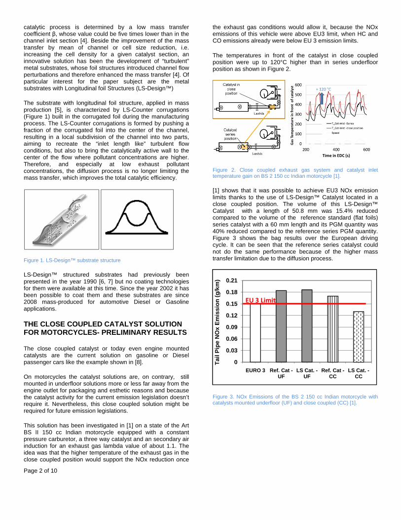
The temperatures in front of the catalyst in close coupled position were up to 120°C higher than in series underfloor position as shown in Figure 2.
Figure 2. Close coupled exhaust gas system and catalyst inlet temperature gain on BS 2 150 cc Indian motorcycle [1].
[1] shows that it was possible to achieve EU3 NOx emission limits thanks to the use of LS-Design™ Catalyst located in a close coupled position. The volume of this LS-Design™ Catalyst with a length of 50.8 mm was 15.4% reduced compared to the volume of the reference standard (flat foils) series catalyst with a 60 mm length and its PGM quantity was 40% reduced compared to the reference series PGM quantity. Figure 3 shows the bag results over the European driving cycle. It can be seen that the reference series catalyst could not do the same performance because of the higher mass transfer limitation due to the diffusion process.
Figure 3. NOx Emissions of the BS 2 150 cc Indian motorcycle with catalysts mounted underfloor (UF) and close coupled (CC) [1].
0
0.03
0.06
0.09
0.12
0.15
0.18
0.21
EURO 3 Ref. Cat -UF
LS Cat. -UF
Ref. Cat -CC
LS Cat. -CC
Tai
l Pip
e N
Ox
Em
issi
on (
g/km
)
EU 3 Limit
Page 3 of 10
Experimental Setup
TEST Vehicle
The test motorcycle is described in Table 1 and represents the state of the art of Indian low power motorcycles, powered by a carbureted engine.
Table 1. Technical data of test vehicle
Test Vehicle
Engine Displacement 180 cm³
Fuel supply system Carburetor
Exhaust Gas After Treatment Three Way Catalyst
Series catalyst substrate D40 x 50.8 mm, 100 cpsi TS [2]
Transmission 5 gears manual
Vehicle Kurb Weight [kg] 145
Maximum Speed (measured on roll bench)
[km/h] 112
Homologation BHARAT Stage III
WMTC Class Sub-Class 2.1
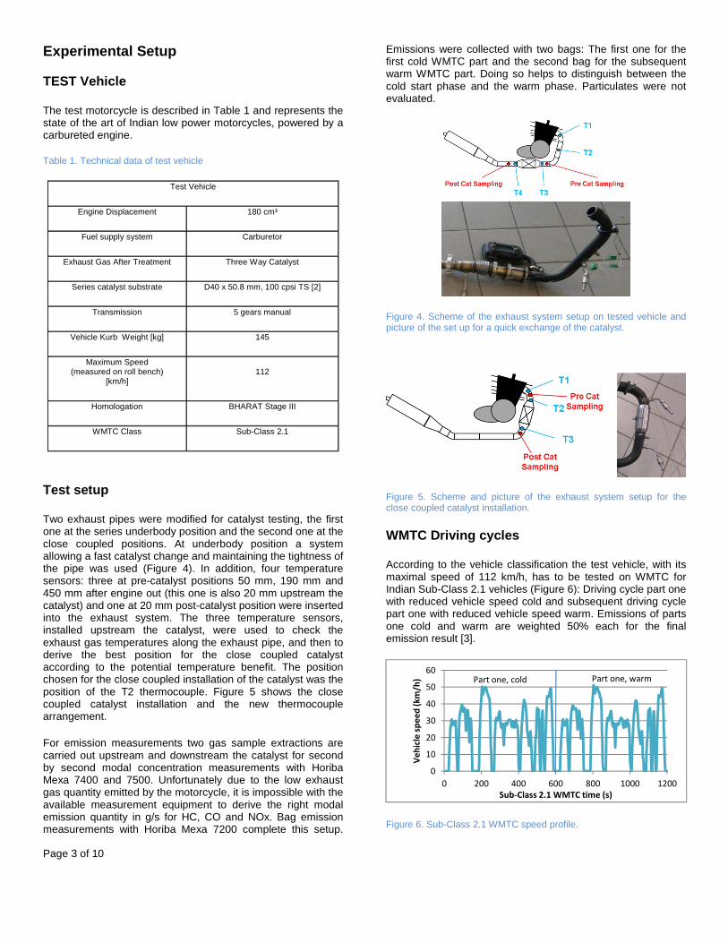
Test setup
Two exhaust pipes were modified for catalyst testing, the first one at the series underbody position and the second one at the close coupled positions. At underbody position a system allowing a fast catalyst change and maintaining the tightness of the pipe was used (Figure 4). In addition, four temperature sensors: three at pre-catalyst positions 50 mm, 190 mm and 450 mm after engine out (this one is also 20 mm upstream the catalyst) and one at 20 mm post-catalyst position were inserted into the exhaust system. The three temperature sensors, installed upstream the catalyst, were used to check the exhaust gas temperatures along the exhaust pipe, and then to derive the best position for the close coupled catalyst according to the potential temperature benefit. The position chosen for the close coupled installation of the catalyst was the position of the T2 thermocouple. Figure 5 shows the close coupled catalyst installation and the new thermocouple arrangement.
For emission measurements two gas sample extractions are carried out upstream and downstream the catalyst for second by second modal concentration measurements with Horiba Mexa 7400 and 7500. Unfortunately due to the low exhaust gas quantity emitted by the motorcycle, it is impossible with the available measurement equipment to derive the right modal emission quantity in g/s for HC, CO and NOx. Bag emission measurements with Horiba Mexa 7200 complete this setup.
Emissions were collected with two bags: The first one for the first cold WMTC part and the second bag for the subsequent warm WMTC part. Doing so helps to distinguish between the cold start phase and the warm phase. Particulates were not evaluated.
Figure 4. Scheme of the exhaust system setup on tested vehicle and picture of the set up for a quick exchange of the catalyst.
Figure 5. Scheme and picture of the exhaust system setup for the close coupled catalyst installation.
WMTC Driving cycles
According to the vehicle classification the test vehicle, with its maximal speed of 112 km/h, has to be tested on WMTC for Indian Sub-Class 2.1 vehicles (Figure 6): Driving cycle part one with reduced vehicle speed cold and subsequent driving cycle part one with reduced vehicle speed warm. Emissions of parts one cold and warm are weighted 50% each for the final emission result [3].
Figure 6. Sub-Class 2.1 WMTC speed profile.
0
10
20
30
40
50
60
0 200 400 600 800 1000 1200
Ve
hic
le s
pe
ed
(k
m/h
)
Sub-Class 2.1 WMTC time (s)
Part one, cold Part one, warm
Page 4 of 10
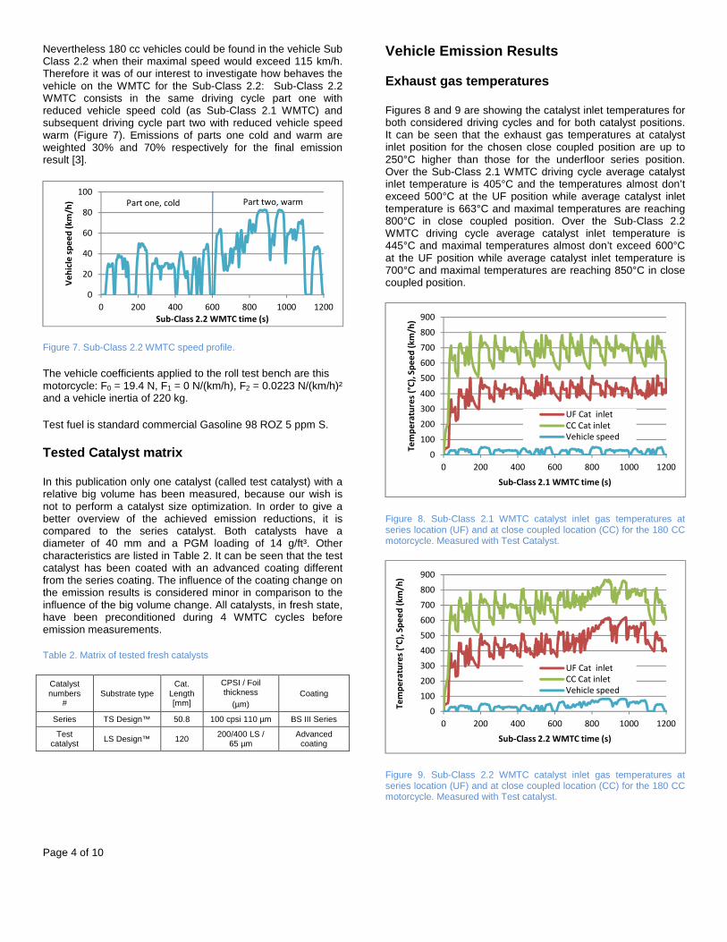
Nevertheless 180 cc vehicles could be found in the vehicle Sub Class 2.2 when their maximal speed would exceed 115 km/h. Therefore it was of our interest to investigate how behaves the vehicle on the WMTC for the Sub-Class 2.2: Sub-Class 2.2 WMTC consists in the same driving cycle part one with reduced vehicle speed cold (as Sub-Class 2.1 WMTC) and subsequent driving cycle part two with reduced vehicle speed warm (Figure 7). Emissions of parts one cold and warm are weighted 30% and 70% respectively for the final emission result [3].
Figure 7. Sub-Class 2.2 WMTC speed profile.
The vehicle coefficients applied to the roll test bench are this motorcycle: F0 = 19.4 N, F1 = 0 N/(km/h), F2 = 0.0223 N/(km/h)² and a vehicle inertia of 220 kg.
Test fuel is standard commercial Gasoline 98 ROZ 5 ppm S.
Tested Catalyst matrix
In this publication only one catalyst (called test catalyst) with a relative big volume has been measured, because our wish is not to perform a catalyst size optimization. In order to give a better overview of the achieved emission reductions, it is compared to the series catalyst. Both catalysts have a diameter of 40 mm and a PGM loading of 14 g/ft³. Other characteristics are listed in Table 2. It can be seen that the test catalyst has been coated with an advanced coating different from the series coating. The influence of the coating change on the emission results is considered minor in comparison to the influence of the big volume change. All catalysts, in fresh state, have been preconditioned during 4 WMTC cycles before emission measurements.
Table 2. Matrix of tested fresh catalysts
Catalyst numbers
# Substrate type
Cat. Length [mm]
CPSI / Foil thickness
(µm) Coating
Series TS Design™ 50.8 100 cpsi 110 µm BS III Series
Test catalyst LS Design™ 120
200/400 LS / 65 µm
Advanced coating
Vehicle Emission Results
Exhaust gas temperatures
Figures 8 and 9 are showing the catalyst inlet temperatures for both considered driving cycles and for both catalyst positions. It can be seen that the exhaust gas temperatures at catalyst inlet position for the chosen close coupled position are up to 250°C higher than those for the underfloor series position. Over the Sub-Class 2.1 WMTC driving cycle average catalyst inlet temperature is 405°C and the temperatures almost don’t exceed 500°C at the UF position while average catalyst inlet temperature is 663°C and maximal temperatures are reaching 800°C in close coupled position. Over the Sub-Class 2.2 WMTC driving cycle average catalyst inlet temperature is 445°C and maximal temperatures almost don’t exceed 600°C at the UF position while average catalyst inlet temperature is 700°C and maximal temperatures are reaching 850°C in close coupled position.
Figure 8. Sub-Class 2.1 WMTC catalyst inlet gas temperatures at series location (UF) and at close coupled location (CC) for the 180 CC motorcycle. Measured with Test Catalyst.
Figure 9. Sub-Class 2.2 WMTC catalyst inlet gas temperatures at series location (UF) and at close coupled location (CC) for the 180 CC motorcycle. Measured with Test catalyst.
0
20
40
60
80
100
0 200 400 600 800 1000 1200
Ve
hic
le s
pe
ed
(k
m/h
)
Sub-Class 2.2 WMTC time (s)
Part one, cold Part two, warm
0
100
200
300
400
500
600
700
800
900
0 200 400 600 800 1000 1200
Te
mp
era
ture
s (°
C),
Sp
ee
d (
km
/h)
Sub-Class 2.1 WMTC time (s)
UF Cat inlet
CC Cat inlet
Vehicle speed
0
100
200
300
400
500
600
700
800
900
0 200 400 600 800 1000 1200
Te
mp
era
ture
s (°
C),
Sp
ee
d (
km
/h)
Sub-Class 2.2 WMTC time (s)
UF Cat inlet
CC Cat inlet
Vehicle speed
Page 5 of 10
Emission Result
Sub-Class 2.2 WMTC
Bag results
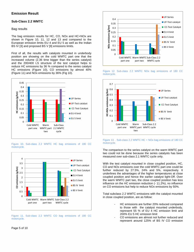
The bag emission results for HC, CO, NOx and HC+NOx are shown in Figure 10, 11, 12 and 13 and compared to the European emission limits EU 4 and EU 5 as well as the Indian BS IV [3] and proposed BS V [9] emissions limits.
First of all, the results with catalysts mounted in underbody position are showing on the cold WMTC part one that the increased volume (2.36 time bigger than the series catalyst) and the 200/400 LS structure of the test catalyst helps to reduce HC emissions by 36 % compared to the series catalyst HC emissions (Figure 10), CO emissions by almost 40% (Figure 11) and NOx emissions by 36% (Fig 10).
Figure 10. Sub-class 2.2 WMTC HC bag emissions of 180 CC motorcycle.
Figure 11. Sub-class 2.2 WMTC CO bag emissions of 180 CC motorcycle.
Figure 12. Sub-class 2.2 WMTC NOx bag emissions of 180 CC motorcycle.
Figure 13. . Sub-class 2.2 WMTC HC + NOx bag emissions of 180 CC motorcycle.
The comparison to the series catalyst on the warm WMTC part two could not be done because the series catalysts has been measured over sub-class 2.1 WMTC cycle only.
With the test catalyst mounted in close coupled position, HC, CO and NOx emissions over the cold WMTC part one could be further reduced by 27.5%, 24% and 5%, respectively. It underlines the advantages of the higher temperatures at close coupled position and hence the earlier catalyst light-Off. Over the warm WMTC part two, the close coupled position has less influence on the HC emission reduction (- 11.2%), no influence on CO emissions but help to reduce NOx emissions by 50%.
Total subclass 2.2 WMTC emissions with the catalyst mounted in close coupled position, are as follow:
- HC emissions are further 20% reduced compared to those with the catalyst mounted underbody, represent 55 % of EU 4 HC emission limit and 200% EU 5 HC emission limit
- CO emissions are almost not further reduced and represent around 125% of BS IV CO emission
0
0.05
0.1
0.15
0.2
0.25
0.3
0.35
0.4
0.45
Cold WMTC
part one
Warm
WMTC part
two
Sub-Class
2.2 WMTC
cycle
HC
em
isis
on
s (g
/km
)
UF-Series
UF-Test catalyst
CC-Test Catalyst
EU 4 limit
EU 5 limit
0
0.5
1
1.5
2
2.5
3
3.5
4
Cold WMTC
part one
Warm WMTC
part two
Sub-Class 2.2
WMTC cycle
CO
em
isis
on
s (g
/km
)
UF-Series
UF-Test catalyst
CC-Test Catalyst
EU 4 limit
EU 5 limit
BS IV limit
BS V limit
0
0.05
0.1
0.15
0.2
0.25
0.3
0.35
0.4
Cold WMTC
part one
Warm WMTC
part two
Sub-Class 2.2
WMTC cycle
NO
x e
mis
iso
ns
(g/k
m)
UF-Series
UF-Test catalyst
CC-Test Catalyst
EU 4 limit
EU 5 limit
BS IV limit
BS V limit
0
0.1
0.2
0.3
0.4
0.5
0.6
0.7
Cold WMTC
part one
Warm
WMTC part
two
Sub-Class 2.2
WMTC cycle
HC
+N
Ox
em
isis
on
s (g
/km
)
UF-Series
UF-Test catalyst
CC-Test Catalyst
BS IV limit
BS V limit
Page 6 of 10
limit and around 220% of EU 4, EU 5 and proposed BS V emission limits
- NOx emissions are further 37 % reduced and represent 35% of proposed BS V NOx Emission limit and 130% of EU 5 NOx emission limit.
- Derived HC+NOx Emissions represent around 75% of BS IV and proposed BS V limits.
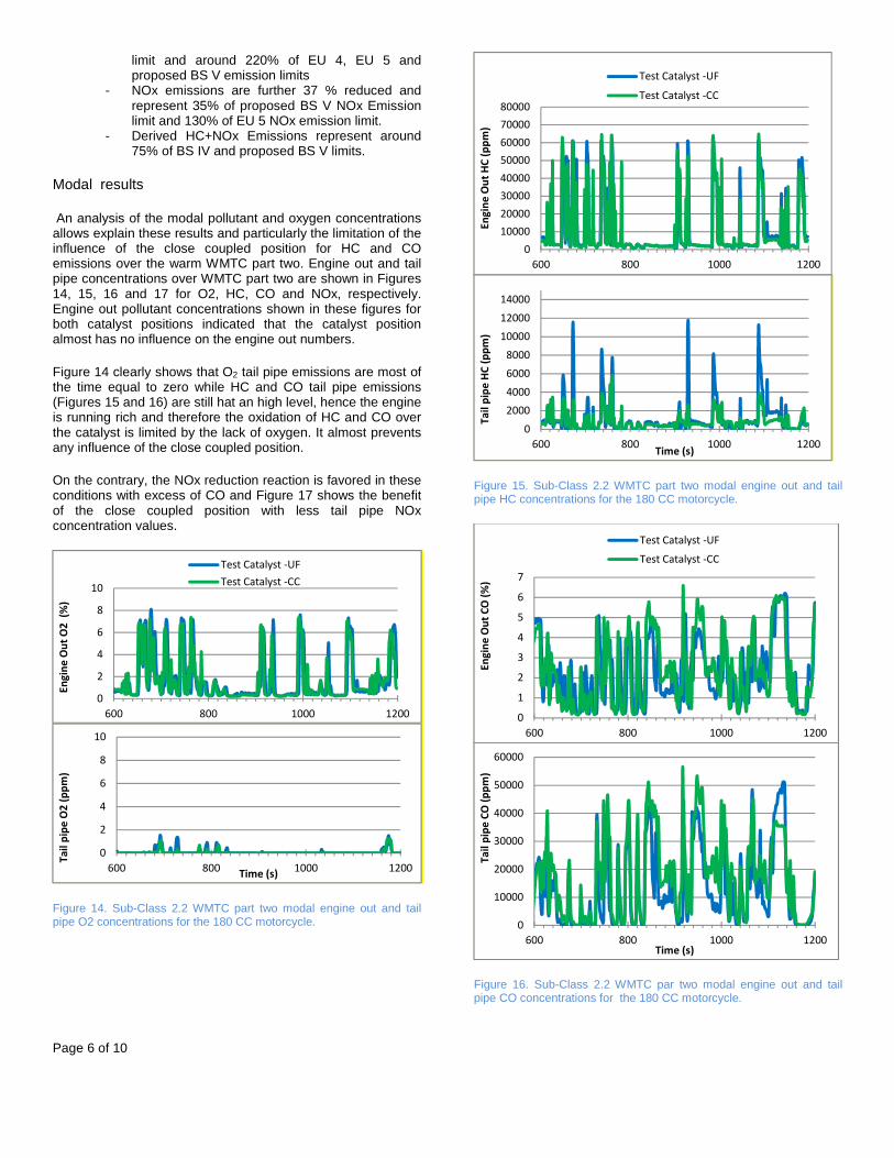
Modal results
An analysis of the modal pollutant and oxygen concentrations allows explain these results and particularly the limitation of the influence of the close coupled position for HC and CO emissions over the warm WMTC part two. Engine out and tail pipe concentrations over WMTC part two are shown in Figures 14, 15, 16 and 17 for O2, HC, CO and NOx, respectively. Engine out pollutant concentrations shown in these figures for both catalyst positions indicated that the catalyst position almost has no influence on the engine out numbers.
Figure 14 clearly shows that O2 tail pipe emissions are most of the time equal to zero while HC and CO tail pipe emissions (Figures 15 and 16) are still hat an high level, hence the engine is running rich and therefore the oxidation of HC and CO over the catalyst is limited by the lack of oxygen. It almost prevents any influence of the close coupled position.
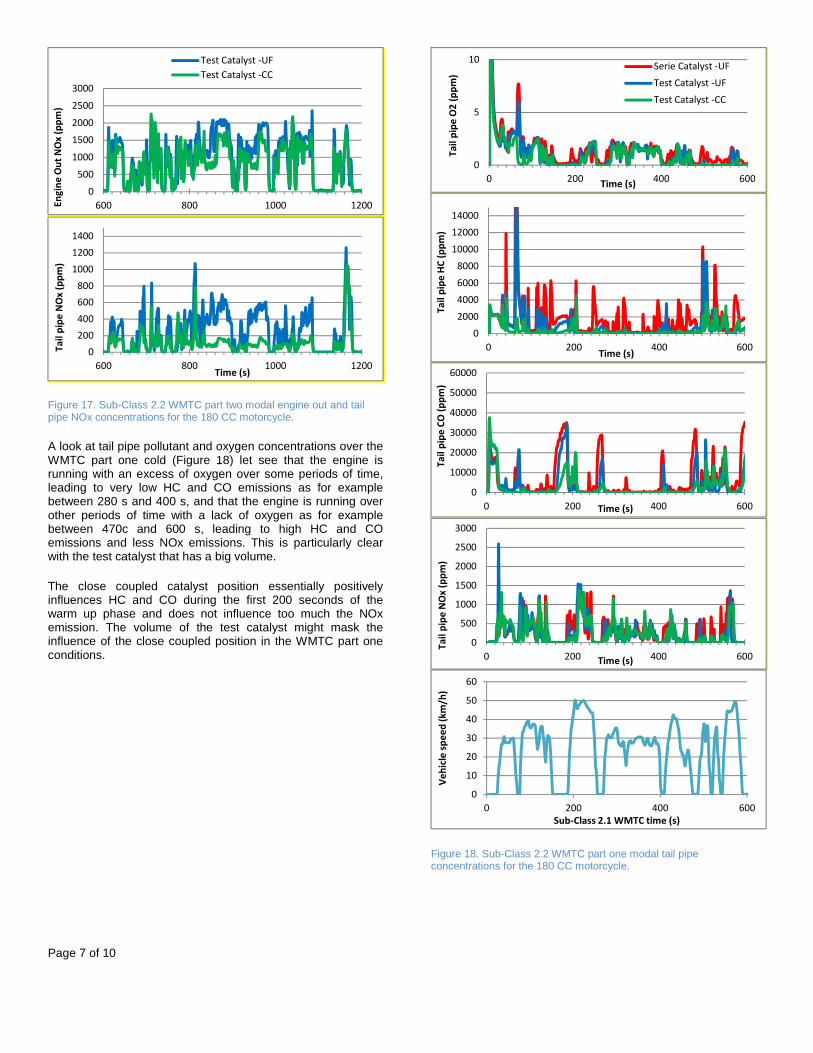
On the contrary, the NOx reduction reaction is favored in these conditions with excess of CO and Figure 17 shows the benefit of the close coupled position with less tail pipe NOx concentration values.
Figure 14. Sub-Class 2.2 WMTC part two modal engine out and tail pipe O2 concentrations for the 180 CC motorcycle.
Figure 15. Sub-Class 2.2 WMTC part two modal engine out and tail pipe HC concentrations for the 180 CC motorcycle.
Figure 16. Sub-Class 2.2 WMTC par two modal engine out and tail pipe CO concentrations for the 180 CC motorcycle.
0
2
4
6
8
10
600 800 1000 1200
En
gin
e O
ut
O2
(%
)
Test Catalyst -UF
Test Catalyst -CC
0
2
4
6
8
10
600 800 1000 1200
Ta
il p
ipe
O2
(p
pm
)
Time (s)
0
10000
20000
30000
40000
50000
60000
70000
80000
600 800 1000 1200
En
gin
e O
ut
HC
(p
pm
)
Test Catalyst -UF
Test Catalyst -CC
0
2000
4000
6000
8000
10000
12000
14000
600 800 1000 1200
Ta
il p
ipe
HC
(p
pm
)
Time (s)
0
1
2
3
4
5
6
7
600 800 1000 1200
En
gin
e O
ut
CO
(%
)
Test Catalyst -UF
Test Catalyst -CC
0
10000
20000
30000
40000
50000
60000
600 800 1000 1200
Ta
il p
ipe
CO
(p
pm
)
Time (s)
Page 7 of 10
Figure 17. Sub-Class 2.2 WMTC part two modal engine out and tail pipe NOx concentrations for the 180 CC motorcycle.
A look at tail pipe pollutant and oxygen concentrations over the WMTC part one cold (Figure 18) let see that the engine is running with an excess of oxygen over some periods of time, leading to very low HC and CO emissions as for example between 280 s and 400 s, and that the engine is running over other periods of time with a lack of oxygen as for example between 470c and 600 s, leading to high HC and CO emissions and less NOx emissions. This is particularly clear with the test catalyst that has a big volume.
The close coupled catalyst position essentially positively influences HC and CO during the first 200 seconds of the warm up phase and does not influence too much the NOx emission. The volume of the test catalyst might mask the influence of the close coupled position in the WMTC part one conditions.
Figure 18. Sub-Class 2.2 WMTC part one modal tail pipe concentrations for the 180 CC motorcycle.
0
500
1000
1500
2000
2500
3000
600 800 1000 1200En
gin
e O
ut
NO
x (
pp
m)
Test Catalyst -UF
Test Catalyst -CC
0
200
400
600
800
1000
1200
1400
600 800 1000 1200
Ta
il p
ipe
NO
x (
pp
m)
Time (s)
0
5
10
0 200 400 600
Ta
il p
ipe
O2
(p
pm
)
Time (s)
Serie Catalyst -UF
Test Catalyst -UF
Test Catalyst -CC
0
2000
4000
6000
8000
10000
12000
14000
0 200 400 600
Ta
il p
ipe
HC
(p
pm
)
Time (s)
0
10000
20000
30000
40000
50000
60000
0 200 400 600
Ta
il p
ipe
CO
(p
pm
)
Time (s)
0
500
1000
1500
2000
2500
3000
0 200 400 600
Ta
il p
ipe
NO
x (
pp
m)
Time (s)
0
10
20
30
40
50
60
0 200 400 600
Ve
hic
le s
pe
ed
(k
m/h
)
Sub-Class 2.1 WMTC time (s)
Page 8 of 10
Sub-Class 2.1 WMTC
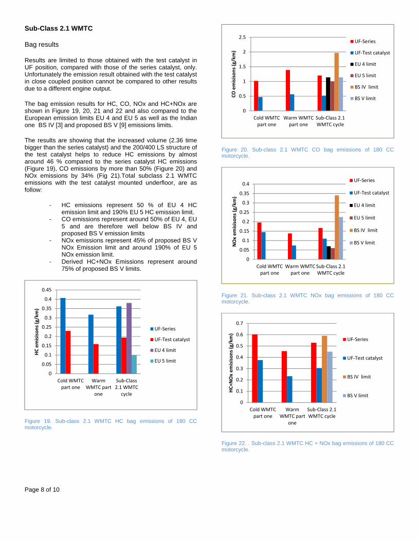
Bag results
Results are limited to those obtained with the test catalyst in UF position, compared with those of the series catalyst, only. Unfortunately the emission result obtained with the test catalyst in close coupled position cannot be compared to other results due to a different engine output.
The bag emission results for HC, CO, NOx and HC+NOx are shown in Figure 19, 20, 21 and 22 and also compared to the European emission limits EU 4 and EU 5 as well as the Indian one BS IV [3] and proposed BS V [9] emissions limits.
The results are showing that the increased volume (2.36 time bigger than the series catalyst) and the 200/400 LS structure of the test catalyst helps to reduce HC emissions by almost around 46 % compared to the series catalyst HC emissions (Figure 19), CO emissions by more than 50% (Figure 20) and NOx emissions by 34% (Fig 21).Total subclass 2.1 WMTC emissions with the test catalyst mounted underfloor, are as follow:
- HC emissions represent 50 % of EU 4 HC emission limit and 190% EU 5 HC emission limit.
- CO emissions represent around 50% of EU 4, EU 5 and are therefore well below BS IV and proposed BS V emission limits
- NOx emissions represent 45% of proposed BS V NOx Emission limit and around 190% of EU 5 NOx emission limit.
- Derived HC+NOx Emissions represent around 75% of proposed BS V limits.
Figure 19. Sub-class 2.1 WMTC HC bag emissions of 180 CC motorcycle.
Figure 20. Sub-class 2.1 WMTC CO bag emissions of 180 CC motorcycle.
Figure 21. Sub-class 2.1 WMTC NOx bag emissions of 180 CC motorcycle.
Figure 22. . Sub-class 2.1 WMTC HC + NOx bag emissions of 180 CC motorcycle.
0
0.05
0.1
0.15
0.2
0.25
0.3
0.35
0.4
0.45
Cold WMTC
part one
Warm
WMTC part
one
Sub-Class
2.1 WMTC
cycle
HC
em
isis
on
s (g
/km
)
UF-Series
UF-Test catalyst
EU 4 limit
EU 5 limit
0
0.5
1
1.5
2
2.5
Cold WMTC
part one
Warm WMTC
part one
Sub-Class 2.1
WMTC cycle
CO
em
isis
on
s (g
/km
)
UF-Series
UF-Test catalyst
EU 4 limit
EU 5 limit
BS IV limit
BS V limit
0
0.05
0.1
0.15
0.2
0.25
0.3
0.35
0.4
Cold WMTC
part one
Warm WMTC
part one
Sub-Class 2.1
WMTC cycle
NO
x e
mis
iso
ns
(g/k
m)
UF-Series
UF-Test catalyst
EU 4 limit
EU 5 limit
BS IV limit
BS V limit
0
0.1
0.2
0.3
0.4
0.5
0.6
0.7
Cold WMTC
part one
Warm
WMTC part
one
Sub-Class 2.1
WMTC cycle
HC
+N
Ox
em
isis
on
s (g
/km
)
UF-Series
UF-Test catalyst
BS IV limit
BS V limit
Page 9 of 10
Discussion
The question we would like to answer is: Would it be possible to further reduce the emissions of the carbureted 180 cc motorcycle if it is classified in the Sub-Class 2.2? The answer seems to be “yes”.
The catalyst volume could be increased until all remaining NOx emissions over the WMTC warm part two are eliminated. This is possible thanks to the excess of CO (see Figure 14). With the additional NOx reduction, that should occur on the cold WMTC part one, NOx emission would be reduced to the EU 5 emission limit level. The excess of HC and CO over the warm WMTC part two indicates that a second oxidation catalyst together with a secondary air induction would be necessary to eliminate these HC and CO emissions. Then HC and CO emissions would reach the levels of EU 5 emission limits.
The combination of two catalysts with a secondary air induction in front of the second catalyst, system seen on China 3 motorcycles, would reduce the emissions to the EU 5 emission limit levels. The first catalyst would be mounted in close coupled position while the second one would be located at today underfloor series position. According to the presented emission results and especially CO emissions this solution would be required for BS IV and proposed BS V stages too.
Is this solution, simple carbureted engine together with a dual catalyst system including a secondary air injection pertinent? It would be only if its cost would remain advantageous. A comparison to other sets of solutions i) piloted carburetor and dual catalyst system and secondary air induction and ii) Fuel injection system with regulated TWC catalyst would have to be performed.
The development of solution for BS IV and beyond legislations might indicate the time for Sub-Class 2.2 Indian motorcycles to adopt a new engine fuel supply technology.
The results previously presented indicate that the carbureted 180 cc motorcycle, if classified in Sub-Class 2.1, would fulfil BS BS V emission legislation. Would it be possible to further reduce its emissions? The increase of the catalyst volume might help to reduce further HC and CO and certainly the NOx too, but some limitations due to lack and excess of oxygen already exist. The gap to EU 5 emission limits for HC and NOx might not be overcome. Even EU 4 NOx emission level might not be reached. If we would now consider the assumption that the carburetor setting will be tuned, i.e. more rich setting, then it would be a similar figure like the previous one described for the motorcycle classified in Sub-Class 2.2.
Summary/Conclusions
This paper is reporting results gained within a comprehensive testing program with a state of the art BS III carbureted motorcycle, aiming to develop catalyst solutions for BS IV legislation and beyond.
Emissions results presented in this publication show that it is possible to further reduce the emissions of this 180 cc Indian motorcycle, whatever its classification, if an increased catalyst
volume and its mounting in close coupled position for an earlier light off are applied.
If classified in Sub-Class 2.1, the vehicle would achieve less than proposed BS V emission limits, what would be highly positive for the air quality of Indian towns, but it is not expected to approach EU 5 emission limits, especially for NOx emission.
If classified Sub-class 2.2 then the vehicle would not meet BS IV due to too high CO emissions, generated by the carbureted engine that is running rich over the warm WMTC part two. A road map to lower emission levels close to EU 5 emission levels for this vehicle class is given. It indicates that the development of BS IV and BS V solutions might lead to technology changes, i.e. replacing the combination carburetor and non-regulated three way catalyst by a combination of a new fuel supply system together with a regulated three way catalyst.
References
1. Jayat F., Seifert S.,Reck A., Babu KVR, “Benefits of LS-Design™, a structured metal foil for two and three wheelers catalyst substrates, to minimize catalyst volumes, PGM loads and the route towards low NOx emissions”, Paper M20100154, 16th APAC
2. Jayat F., Seifert S., Babu KVR, Waje S., “Application of a LS Metal Catalyst Substrate for BS IV Two and Three Wheelers”, SAE 2015-26-0098, SIAT 2015
3. The Gazette of India, PART II—Section 3—Sub-section (i), No. 344 NEW DELHI, FRIDAY, JULY 4, 2014/ASADHA 13, 1936, REGD. NO. D. L.-33004/99
4. Brueck R., Hirth P., Maus W., Deutschmann O., Mladenov N., “Fundamentals of Laminar and Turbulent Catalysis; Turbulent beats Laminar”, 27. Internationales Wiener Motorensymposium, 2006
5. Nagel T., Kruse C. “Einsatz hocheffektiver, turbulenter Metallträger unter den begrenzten Bauraumverhältnissen heutiger EU V Großserien-Diesel PKW“; 4. Emission Control, Dresden, Mai 29-30, 2008
6. Behr GmbH; “Schlitze für mehr Leistung – Katalysatorträger METALIT-S“; Automobil-Produktion, 1989, 3, Seite 166
7. R. Brück, J. Diringer, U. Martin, W. Maus; Emitec GmbH: ”Flow Improved Efficiency by New Cell Structures in Metallic Substrates”; SAE 950788
8. M. Laurell, J. Sjörs, S. Ovesson, M. Lundgren, R. Brueck, M. Presti, “The innovative exhaust gas aftertreatment system for the new Volvo 4 Cylinder Engines; a unit catalyst system for gasoline and diesel cars”, 22nd Achen Colloquium Automobile and Engine Technology 2013.
9. Executive Summary on Indian “Auto fuel Vision & Policy 2025”, 2nd July 2014
Contact Information
If any question please contact Dr. Francois Jayat at following e-mail address [email protected].
Page 10 of 10
Acknowledgments
The Authors gratefully thank the Company Automotive Catalyst Umicore AG & Co. KG for the supply of the catalyst coating used in this development work.
Abbreviations/ Definitions
BS: Bharat Stage legislation
EU 3, EU 4: European emission legislation stages 3 and 4
Sub-Class 2.1: Vehicles that fulfill the following specifications belong to class 2-1: Engine capacity < 150 cm³ and 100 km/h <Vmax<115 km/h or engine capacity >= 150 cm³ and Vmax< 115 km/h
Sub-Class 2.2: Vehicles that fulfill the following specifications belong to class 2-2: 115 km/h< Vmax< 130 km/h
LS / LS-Design™: Foil structure / Design with Longitudinal Structure (LS)
TS Design™: Foil structure / Design with Transversal Structure (TS)
WMTC: World-wide harmonized Motorcycle Test Cycle
PGM: Platinum Group Metal
HC: Hydrocarbons
CO: Carbon monoxide
NOx: Nitrogen oxides