Embed Size (px)
Citation preview
January 27, 2011
CLEAN LINE ENERGY
GRAIN BELT EXPRESS HVDC LINE
PRELIMINARY DESIGN CRITERIA PROJECT NUMBER: 121586
PROJECT CONTACT: BRIAN BERKEBILE EMAIL: [email protected] PHONE: 803-835-5902
fit a 4’ wide and 3.5’ tall photo
Schedule AWG-3 Page 1 of 94
POWER ENGINEERS, INC.
FMC 009-009 (DD-DES-01) DES CRITERIA (01/31/10) MW 121586
PRELIMINARY DESIGN CRITERIA
PREPARED FOR: CLEAN LINE ENERGY PREPARED BY: BRIAN BERKEBILE
PHONE 803-835-5902 EMAIL [email protected]
REVISION HISTORY
DATE REVISED BY REVISION
A BHB DRAFT for Review
Schedule AWG-3 Page 2 of 94
POWER ENGINEERS, INC.
FMC 009-009 (DD-DES-01) DES CRITERIA (01/31/10) MW 121586 PAGE i
TABLE OF CONTENTS
ABBREVIATIONS ..................................................................................................................................... IV
GENERAL ...................................................................................................................................................... 1
PROJECT INFORMATION ................................................................................................................................ 1 CORRESPONDENCE/PROJECT PERSONNEL .................................................................................................... 1
POWER Engineers, Inc. ........................................................................................................................... 1 Client ........................................................................................................................................................ 2
PROJECT DESCRIPTION ................................................................................................................................. 3
CODE(S) AND LOADING CONDITIONS ................................................................................................. 3
CONTROLLING CODE(S) ................................................................................................................................ 3 LOADING CONDITIONS FOR NON-DEADEND STRUCTURES .......................................................................... 4 LOADING CONDITIONS FOR DEADEND STRUCTURES ................................................................................... 5
WIRE ............................................................................................................................................................... 6
TRANSMISSION CONDUCTOR ........................................................................................................................ 6 AMPACITY .................................................................................................................................................... 6 OPGW .......................................................................................................................................................... 7 SHIELD WIRE ................................................................................................................................................ 7 CONDUCTOR SAG-TENSION LIMITS .............................................................................................................. 8 OPGW SAG-TENSION LIMITS ....................................................................................................................... 8 CREEP-STRETCH CRITERIA ........................................................................................................................... 9 GALLOPING ................................................................................................................................................... 9 ALUMINUM IN COMPRESSION ....................................................................................................................... 9
STRUCTURES ............................................................................................................................................... 9
CIRCUITS ....................................................................................................................................................... 9 MATERIAL .................................................................................................................................................... 9 CONFIGURATION ........................................................................................................................................... 9 FOUNDATIONS ............................................................................................................................................ 10 CALCULATED LIGHTNING OUTAGES .......................................................................................................... 10 DISTANCE BETWEEN DEADENDS ............................................................................................................... 10 OTHER ......................................................................................................................................................... 10
GUYS AND ANCHORS .............................................................................................................................. 10
GUYS ........................................................................................................................................................... 10 GUY CONNECTION ...................................................................................................................................... 10 GUY STRAIN INSULATORS .......................................................................................................................... 11 GUY GUARDS .............................................................................................................................................. 11 ANCHORS .................................................................................................................................................... 11
HARDWARE ................................................................................................................................................ 11
DEADEND ATTACHMENT ............................................................................................................................ 11 SUSPENSION ATTACHMENT ........................................................................................................................ 11 BRACING ..................................................................................................................................................... 11 VIBRATION ANALYSIS ................................................................................................................................ 12
Schedule AWG-3 Page 3 of 94
POWER ENGINEERS, INC.
FMC 009-009 (DD-DES-01) DES CRITERIA (01/31/10) MW 121586 PAGE ii
SPACER REQUIREMENTS ............................................................................................................................. 12
INSULATION ............................................................................................................................................... 12
TYPE-TRANSMISSION ................................................................................................................................. 12 MATERIAL TRANSMISSION ......................................................................................................................... 12 RATINGS-TRANSMISSION ........................................................................................................................... 13
RIGHT-OF-WAY ......................................................................................................................................... 14
DESCRIPTION .............................................................................................................................................. 14 RIGHT-OF-WAY WIDTH CALCULATIONS FOR BLOWOUT ........................................................................... 14 ELECTRIC FIELD AFFECTS .......................................................................................................................... 15 CORONA ...................................................................................................................................................... 15
CLEARANCES ............................................................................................................................................ 15
CLEARANCE TO STRUCTURE/INSULATOR SWING ....................................................................................... 16 GROUND CLEARANCE ................................................................................................................................. 16
5 milli Amp Rule .................................................................................................................................... 16 CLEARANCE BETWEEN WIRES ON DIFFERENT SUPPORTING STRUCTURES ................................................ 16 CLEARANCE TO STRUCTURES OF ANOTHER LINE ...................................................................................... 17 HORIZONTAL CLEARANCE BETWEEN LINE CONDUCTORS AT FIXED SUPPORTS ....................................... 17 VERTICAL CLEARANCE BETWEEN LINE CONDUCTORS ............................................................................. 17 RADIAL CLEARANCE FROM LINE CONDUCTORS TO SUPPORTS, AND TO VERTICAL OR LATERAL CONDUCTORS, SPAN OR GUY WIRES ATTACHED TO THE SAME SUPPORT ................................................ 17
MISCELLANEOUS ..................................................................................................................................... 18
GROUNDING REQUIREMENTS (TYPE AND FREQUENCY OF GROUNDING REQUIRED) .................................. 18 SPECIAL EQUIPMENT .................................................................................................................................. 18 MATERIAL .................................................................................................................................................. 18 ENVIRONMENTAL PROTECTION .................................................................................................................. 18
DRAWINGS AND MAPS ............................................................................................................................ 19
MAPS .......................................................................................................................................................... 19 DRAWING REQUIREMENTS ......................................................................................................................... 19
SUSTATION/SWITCHYARD INTERFACE ........................................................................................... 20
OTHER.......................................................................................................................................................... 20
APPENDIX A – CLEARANCES CALCULATIONS TABLE
APPENDIX B – OPGW DETAILED SPECIFICATION
APPENDIX C – LIGHTNING ALGORITHM: EXPECTED CHARGE CALCULATION AT LINE LOCATION
APPENDIX D- OPGW OUTER LAYER’S WIRE DIAMETER CALCULATION BASED ON EXPECTED LIGHTNING CHARGE AT LINE LOCATION
APPENDIX E – SAG & TENSION FILES
APPENDIX F – AMPACITY CALCULATIONS
APPENDIX G- COMPARISON OF STRUCTURES TYPES
Schedule AWG-3 Page 4 of 94
POWER ENGINEERS, INC.
FMC 009-009 (DD-DES-01) DES CRITERIA (01/31/10) MW 121586 PAGE iii
APPENDIX H- PLS-CADD WIR FILE WITH DC RESISTANCES
APPENDIX I- PRELIMINARY CONDUCTORS COMPARISON
APPENDIX J-FOUNDATION DESIGN CRITERIA
Schedule AWG-3 Page 5 of 94
POWER ENGINEERS, INC.
FMC 009-009 (DD-DES-01) DES CRITERIA (01/31/10) MW 121586 PAGE iv
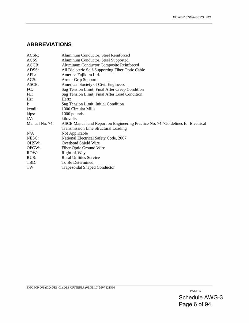
ABBREVIATIONS ACSR: Aluminum Conductor, Steel Reinforced ACSS: Aluminum Conductor, Steel Supported ACCR: Aluminum Conductor Composite Reinforced ADSS: All Dielectric Self-Supporting Fiber Optic Cable AFL: America Fujikura Ltd. AGS: Armor Grip Support ASCE: American Society of Civil Engineers FC: Sag Tension Limit, Final After Creep Condition FL: Sag Tension Limit, Final After Load Condition Hz: Hertz I: Sag Tension Limit, Initial Condition kcmil: 1000 Circular Mills kips: 1000 pounds kV: kilovolts Manual No. 74 ASCE Manual and Report on Engineering Practice No. 74 “Guidelines for Electrical
Transmission Line Structural Loading N/A Not Applicable NESC: National Electrical Safety Code, 2007 OHSW: Overhead Shield Wire OPGW: Fiber Optic Ground Wire ROW: Right-of-Way RUS: Rural Utilities Service TBD: To Be Determined TW: Trapezoidal Shaped Conductor
Schedule AWG-3 Page 6 of 94
POWER ENGINEERS, INC.
FMC 009-009 (DD-DES-01) DES CRITERIA (01/31/10) MW 121586 PAGE 1
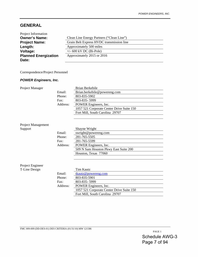
GENERAL Project Information Owner’s Name: Clean Line Energy Partners (“Clean Line”) Project Name: Grain Belt Express HVDC transmission line Length: Approximately 500 miles Voltage: +/- 600 kV DC (Bi-Pole) Planned Energization Date:
Approximately 2015 or 2016
Correspondence/Project Personnel POWER Engineers, Inc. Project Manager
Brian Berkebile
Email: [email protected] Phone: 803-835-5902 Fax: 803-835- 5999 Address: POWER Engineers, Inc. 1057 521 Corporate Center Drive Suite 150 Fort Mill, South Carolina 29707 Project Management Support
Shayne Wright
Email: [email protected] Phone: 281-765-5505 Fax: 281-765-5599 Address: POWER Engineers, Inc. 509 N Sam Houston Pkwy East Suite 200 Houston, Texas 77060 Project Engineer T-Line Design
Tim Kautz
Email: [email protected] Phone: 803-835-5901 Fax: 803-835- 5999 Address: POWER Engineers, Inc. 1057 521 Corporate Center Drive Suite 150 Fort Mill, South Carolina 29707
Schedule AWG-3 Page 7 of 94
POWER ENGINEERS, INC.
FMC 009-009 (DD-DES-01) DES CRITERIA (01/31/10) MW 121586 PAGE 2
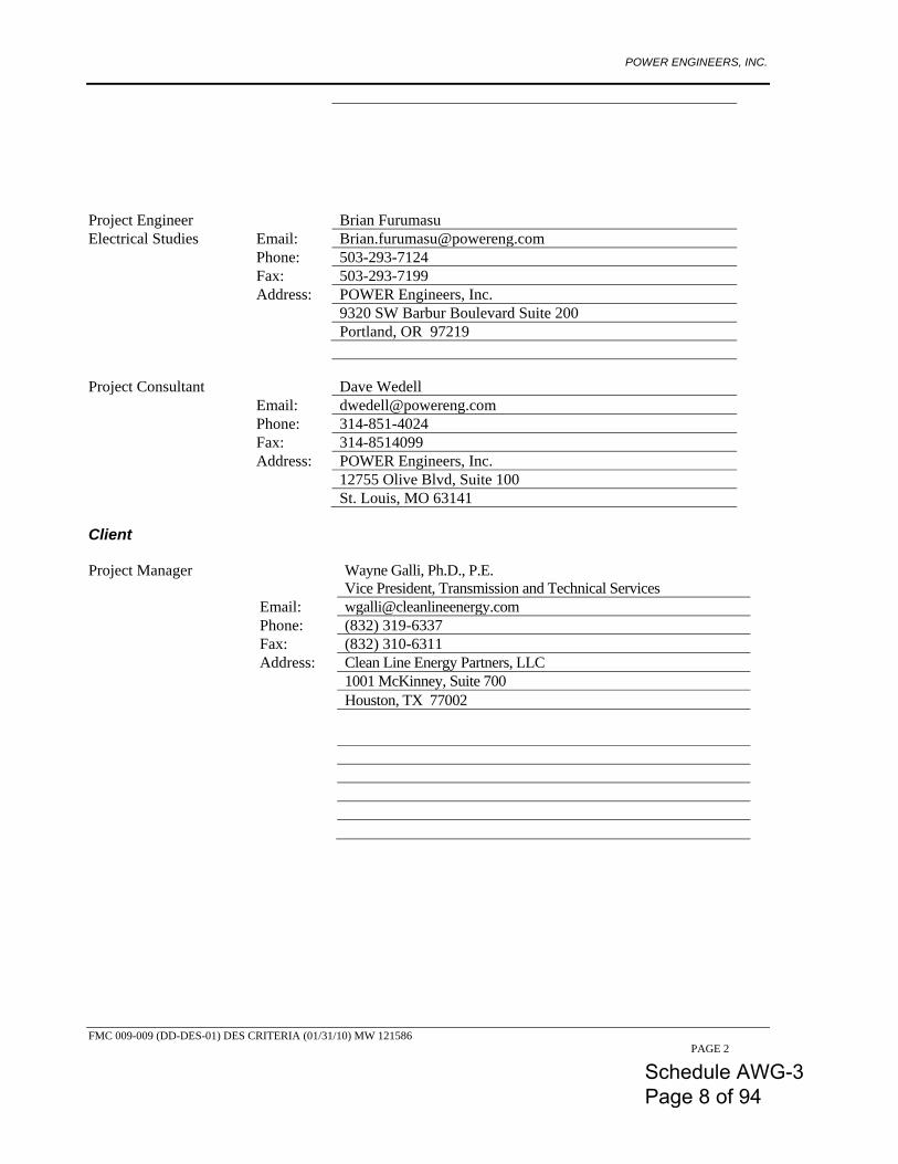
Project Engineer
Brian Furumasu
Electrical Studies Email: [email protected] Phone: 503-293-7124 Fax: 503-293-7199 Address: POWER Engineers, Inc. 9320 SW Barbur Boulevard Suite 200 Portland, OR 97219 Project Consultant
Dave Wedell
Email: [email protected] Phone: 314-851-4024 Fax: 314-8514099 Address: POWER Engineers, Inc. 12755 Olive Blvd, Suite 100 St. Louis, MO 63141 Client Project Manager
Wayne Galli, Ph.D., P.E. Vice President, Transmission and Technical Services
Email: [email protected] Phone: (832) 319-6337 Fax: (832) 310-6311 Address: Clean Line Energy Partners, LLC 1001 McKinney, Suite 700 Houston, TX 77002
Schedule AWG-3 Page 8 of 94
POWER ENGINEERS, INC.
FMC 009-009 (DD-DES-01) DES CRITERIA (01/31/10) MW 121586 PAGE 3
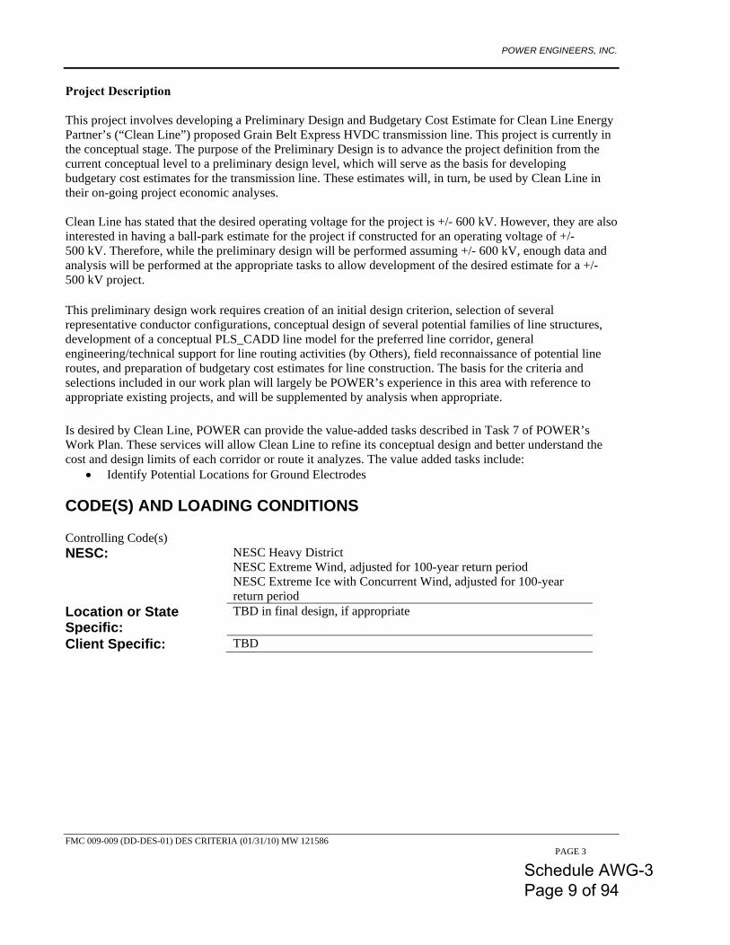
Project Description This project involves developing a Preliminary Design and Budgetary Cost Estimate for Clean Line Energy Partner’s (“Clean Line”) proposed Grain Belt Express HVDC transmission line. This project is currently in the conceptual stage. The purpose of the Preliminary Design is to advance the project definition from the current conceptual level to a preliminary design level, which will serve as the basis for developing budgetary cost estimates for the transmission line. These estimates will, in turn, be used by Clean Line in their on-going project economic analyses. Clean Line has stated that the desired operating voltage for the project is +/- 600 kV. However, they are also interested in having a ball-park estimate for the project if constructed for an operating voltage of +/- 500 kV. Therefore, while the preliminary design will be performed assuming +/- 600 kV, enough data and analysis will be performed at the appropriate tasks to allow development of the desired estimate for a +/- 500 kV project. This preliminary design work requires creation of an initial design criterion, selection of several representative conductor configurations, conceptual design of several potential families of line structures, development of a conceptual PLS_CADD line model for the preferred line corridor, general engineering/technical support for line routing activities (by Others), field reconnaissance of potential line routes, and preparation of budgetary cost estimates for line construction. The basis for the criteria and selections included in our work plan will largely be POWER’s experience in this area with reference to appropriate existing projects, and will be supplemented by analysis when appropriate. Is desired by Clean Line, POWER can provide the value-added tasks described in Task 7 of POWER’s Work Plan. These services will allow Clean Line to refine its conceptual design and better understand the cost and design limits of each corridor or route it analyzes. The value added tasks include:
• Identify Potential Locations for Ground Electrodes CODE(S) AND LOADING CONDITIONS Controlling Code(s) NESC: NESC Heavy District
NESC Extreme Wind, adjusted for 100-year return period NESC Extreme Ice with Concurrent Wind, adjusted for 100-year return period
Location or State Specific:
TBD in final design, if appropriate
Client Specific: TBD
Schedule AWG-3 Page 9 of 94
POWER ENGINEERS, INC.
FMC 009-009 (DD-DES-01) DES CRITERIA (01/31/10) MW 121586 PAGE 4
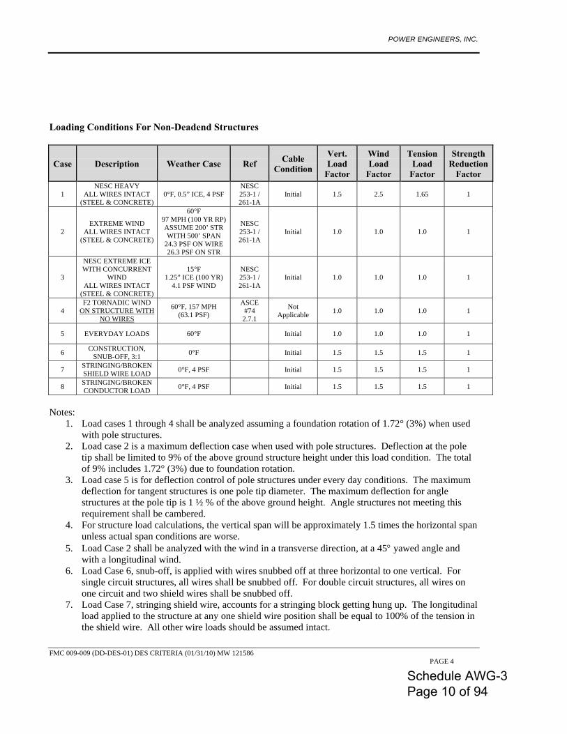
Loading Conditions For Non-Deadend Structures
Case Description Weather Case Ref Cable Condition
Vert. Load
Factor
Wind Load
Factor
Tension Load
Factor
Strength Reduction
Factor
1 NESC HEAVY
ALL WIRES INTACT (STEEL & CONCRETE)
0°F, 0.5” ICE, 4 PSF NESC 253-1 / 261-1A
Initial 1.5 2.5 1.65 1
2 EXTREME WIND
ALL WIRES INTACT (STEEL & CONCRETE)
60°F 97 MPH (100 YR RP) ASSUME 200’ STR WITH 500’ SPAN
24.3 PSF ON WIRE 26.3 PSF ON STR
NESC 253-1 / 261-1A
Initial 1.0 1.0 1.0 1
3
NESC EXTREME ICE WITH CONCURRENT
WIND ALL WIRES INTACT
(STEEL & CONCRETE)
15°F 1.25” ICE (100 YR)
4.1 PSF WIND
NESC 253-1 / 261-1A
Initial 1.0 1.0 1.0 1
4 F2 TORNADIC WIND
ON STRUCTURE WITH NO WIRES
60°F, 157 MPH (63.1 PSF)
ASCE #74
2.7.1
Not Applicable 1.0 1.0 1.0 1
5 EVERYDAY LOADS 60°F Initial 1.0 1.0 1.0 1
6 CONSTRUCTION, SNUB-OFF, 3:1 0°F Initial 1.5 1.5 1.5 1
7 STRINGING/BROKEN SHIELD WIRE LOAD 0°F, 4 PSF Initial 1.5 1.5 1.5 1
8 STRINGING/BROKEN CONDUCTOR LOAD 0°F, 4 PSF Initial 1.5 1.5 1.5 1
Notes:
1. Load cases 1 through 4 shall be analyzed assuming a foundation rotation of 1.72° (3%) when used with pole structures.
2. Load case 2 is a maximum deflection case when used with pole structures. Deflection at the pole tip shall be limited to 9% of the above ground structure height under this load condition. The total of 9% includes 1.72° (3%) due to foundation rotation.
3. Load case 5 is for deflection control of pole structures under every day conditions. The maximum deflection for tangent structures is one pole tip diameter. The maximum deflection for angle structures at the pole tip is 1 ½ % of the above ground height. Angle structures not meeting this requirement shall be cambered.
4. For structure load calculations, the vertical span will be approximately 1.5 times the horizontal span unless actual span conditions are worse.
5. Load Case 2 shall be analyzed with the wind in a transverse direction, at a 45° yawed angle and with a longitudinal wind.
6. Load Case 6, snub-off, is applied with wires snubbed off at three horizontal to one vertical. For single circuit structures, all wires shall be snubbed off. For double circuit structures, all wires on one circuit and two shield wires shall be snubbed off.
7. Load Case 7, stringing shield wire, accounts for a stringing block getting hung up. The longitudinal load applied to the structure at any one shield wire position shall be equal to 100% of the tension in the shield wire. All other wire loads should be assumed intact.
Schedule AWG-3 Page 10 of 94
POWER ENGINEERS, INC.
FMC 009-009 (DD-DES-01) DES CRITERIA (01/31/10) MW 121586 PAGE 5
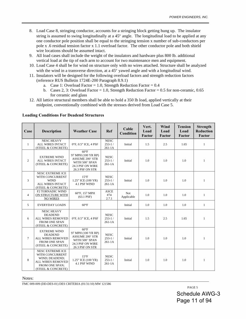
8. Load Case 8, stringing conductor, accounts for a stringing block getting hung up. The insulator string is assumed to swing longitudinally at a 45° angle. The longitudinal load to be applied at any one conductor pole position shall be equal to the stringing tension x number of sub-conductors per pole x .6 residual tension factor x 1.1 overload factor. The other conductor pole and both shield wire locations should be assumed intact.
9. All load cases shall include the weight of the insulators and hardware plus 800 lb. additional vertical load at the tip of each arm to account for two maintenance men and equipment.
10. Load Case 4 shall be for wind on structure only with no wires attached. Structure shall be analyzed with the wind in a transverse direction, at a 45° yawed angle and with a longitudinal wind.
11. Insulators will be designed for the following overload factors and strength reduction factors (reference RUS Bulletin 1724E-200 Paragraph 8.9.1)
a. Case 1: Overload Factor = 1.0, Strength Reduction Factor = 0.4 b. Cases 2, 3: Overload Factor = 1.0, Strength Reduction Factor = 0.5 for non-ceramic, 0.65
for ceramic and glass 12. All lattice structural members shall be able to hold a 350 lb load, applied vertically at their
midpoint, conventionally combined with the stresses derived from Load Case 5. Loading Conditions For Deadend Structures
Case Description Weather Case Ref Cable Condition
Vert. Load
Factor
Wind Load
Factor
Tension Load
Factor
Strength Reduction
Factor
1 NESC HEAVY
ALL WIRES INTACT (STEEL & CONCRETE)
0°F, 0.5” ICE, 4 PSF NESC 253-1 / 261-1A
Initial 1.5 2.5 1.65 1
2 EXTREME WIND
ALL WIRES INTACT (STEEL & CONCRETE)
60°F 97 MPH (100 YR RP) ASSUME 200’ STR WITH 500’ SPAN
24.3 PSF ON WIRE 26.3 PSF ON STR
NESC 253-1 / 261-1A
Initial 1.0 1.0 1.0 1
3
NESC EXTREME ICE WITH CONCURRENT
WIND ALL WIRES INTACT
(STEEL & CONCRETE)
15°F 1.25” ICE (100 YR)
4.1 PSF WIND
NESC 253-1 / 261-1A
Initial 1.0 1.0 1.0 1
4 F2 TORNADIC WIND
ON STRUCTURE WITH NO WIRES
60°F, 157 MPH (63.1 PSF)
ASCE #74
2.7.1
Not Applicable 1.0 1.0 1.0 1
5 EVERYDAY LOADS 60°F Initial 1.0 1.0 1.0 1
6
NESC HEAVY DEADEND
ALL WIRES REMOVED FROM ONE SPAN
(STEEL & CONCRETE)
0°F, 0.5” ICE, 4 PSF NESC 253-1 / 261-1A
Initial 1.5 2.5 1.65 1
7
EXTREME WIND DEADEND
ALL WIRES REMOVED FROM ONE SPAN
(STEEL & CONCRETE)
60°F 97 MPH (100 YR RP) ASSUME 200’ STR WITH 500’ SPAN
24.3 PSF ON WIRE 26.3 PSF ON STR
NESC 253-1 / 261-1A
Initial 1.0 1.0 1.0 1
8
NESC EXTREME ICE WITH CONCURRENT
WIND; DEADEND; ALL WIRES REMOVED
FROM ONE SPAN; (STEEL & CONCRETE)
15°F 1.25” ICE (100 YR)
4.1 PSF WIND
NESC 253-1 / 261-1A
Initial 1.0 1.0 1.0 1
Notes:
Schedule AWG-3 Page 11 of 94
POWER ENGINEERS, INC.
FMC 009-009 (DD-DES-01) DES CRITERIA (01/31/10) MW 121586 PAGE 6
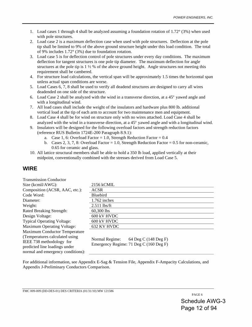
1. Load cases 1 through 4 shall be analyzed assuming a foundation rotation of 1.72° (3%) when used with pole structures.
2. Load case 2 is a maximum deflection case when used with pole structures. Deflection at the pole tip shall be limited to 9% of the above ground structure height under this load condition. The total of 9% includes 1.72° (3%) due to foundation rotation.
3. Load case 5 is for deflection control of pole structures under every day conditions. The maximum deflection for tangent structures is one pole tip diameter. The maximum deflection for angle structures at the pole tip is 1 ½ % of the above ground height. Angle structures not meeting this requirement shall be cambered.
4. For structure load calculations, the vertical span will be approximately 1.5 times the horizontal span unless actual span conditions are worse.
5. Load Cases 6, 7, 8 shall be used to verify all deadend structures are designed to carry all wires deadended on one side of the structure.
6. Load Case 2 shall be analyzed with the wind in a transverse direction, at a 45° yawed angle and with a longitudinal wind.
7. All load cases shall include the weight of the insulators and hardware plus 800 lb. additional vertical load at the tip of each arm to account for two maintenance men and equipment.
8. Load Case 4 shall be for wind on structure only with no wires attached. Load Case 4 shall be analyzed with the wind in a transverse direction, at a 45° yawed angle and with a longitudinal wind.
9. Insulators will be designed for the following overload factors and strength reduction factors (reference RUS Bulletin 1724E-200 Paragraph 8.9.1):
a. Case 1, 6: Overload Factor = 1.0, Strength Reduction Factor = 0.4 b. Cases 2, 3, 7, 8: Overload Factor = 1.0, Strength Reduction Factor = 0.5 for non-ceramic,
0.65 for ceramic and glass. 10. All lattice structural members shall be able to hold a 350 lb load, applied vertically at their
midpoint, conventionally combined with the stresses derived from Load Case 5. WIRE Transmission Conductor Size (kcmil/AWG): 2156 kCMIL Composition (ACSR, AAC, etc.): ACSR Code Word: Bluebird Diameter: 1.762 inches Weight: 2.511 lbs/ft Rated Breaking Strength: 60,300 lbs Design Voltage: 600 kV HVDC Typical Operating Voltage: 600 kV HVDC Maximum Operating Voltage: 632 KV HVDC Maximum Conductor Temperature (Temperatures calculated using IEEE 738 methodology for predicted line loadings under normal and emergency conditions):
Normal Regime: 64 Deg C (148 Deg F) Emergency Regime: 71 Deg C (160 Deg F)
For additional information, see Appendix E-Sag & Tension File, Appendix F-Ampacity Calculations, and Appendix J-Preliminary Conductors Comparison.
Schedule AWG-3 Page 12 of 94
POWER ENGINEERS, INC.
FMC 009-009 (DD-DES-01) DES CRITERIA (01/31/10) MW 121586 PAGE 7
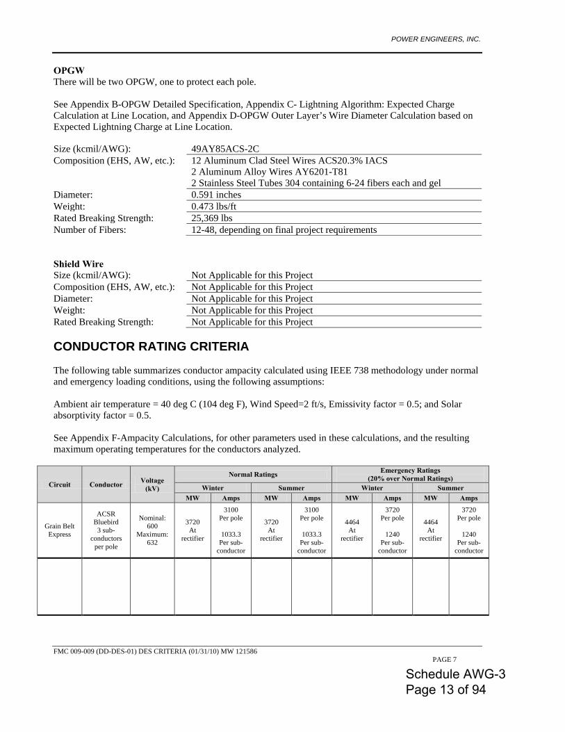
OPGW There will be two OPGW, one to protect each pole. See Appendix B-OPGW Detailed Specification, Appendix C- Lightning Algorithm: Expected Charge Calculation at Line Location, and Appendix D-OPGW Outer Layer’s Wire Diameter Calculation based on Expected Lightning Charge at Line Location. Size (kcmil/AWG): 49AY85ACS-2C Composition (EHS, AW, etc.): 12 Aluminum Clad Steel Wires ACS20.3% IACS
2 Aluminum Alloy Wires AY6201-T81 2 Stainless Steel Tubes 304 containing 6-24 fibers each and gel
Diameter: 0.591 inches Weight: 0.473 lbs/ft Rated Breaking Strength: 25,369 lbs Number of Fibers: 12-48, depending on final project requirements Shield Wire Size (kcmil/AWG): Not Applicable for this Project Composition (EHS, AW, etc.): Not Applicable for this Project Diameter: Not Applicable for this Project Weight: Not Applicable for this Project Rated Breaking Strength: Not Applicable for this Project CONDUCTOR RATING CRITERIA The following table summarizes conductor ampacity calculated using IEEE 738 methodology under normal and emergency loading conditions, using the following assumptions: Ambient air temperature = 40 deg C (104 deg F), Wind Speed=2 ft/s, Emissivity factor = 0.5; and Solar absorptivity factor = 0.5. See Appendix F-Ampacity Calculations, for other parameters used in these calculations, and the resulting maximum operating temperatures for the conductors analyzed.
Circuit Conductor Voltage (kV)
Normal Ratings Emergency Ratings (20% over Normal Ratings)
Winter Summer Winter Summer MW Amps MW Amps MW Amps MW Amps
Grain Belt Express
ACSR Bluebird
3 sub-conductors
per pole
Nominal: 600
Maximum: 632
3720 At
rectifier
3100 Per pole
1033.3
Per sub-conductor
3720 At
rectifier
3100 Per pole
1033.3
Per sub-conductor
4464 At
rectifier
3720 Per pole
1240
Per sub-conductor
4464 At
rectifier
3720 Per pole
1240
Per sub-conductor
Schedule AWG-3 Page 13 of 94
POWER ENGINEERS, INC.
FMC 009-009 (DD-DES-01) DES CRITERIA (01/31/10) MW 121586 PAGE 8
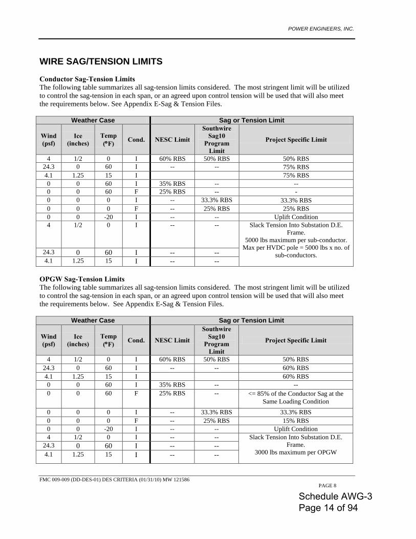
WIRE SAG/TENSION LIMITS Conductor Sag-Tension Limits The following table summarizes all sag-tension limits considered. The most stringent limit will be utilized to control the sag-tension in each span, or an agreed upon control tension will be used that will also meet the requirements below. See Appendix E-Sag & Tension Files.
Weather Case Sag or Tension Limit
Wind (psf)
Ice (inches)
Temp (°F) Cond. NESC Limit
Southwire Sag10
Program Limit
Project Specific Limit
4 1/2 0 I 60% RBS 50% RBS 50% RBS 24.3 0 60 I -- -- 75% RBS 4.1 1.25 15 I 75% RBS 0 0 60 I 35% RBS -- -- 0 0 60 F 25% RBS -- - 0 0 0 I -- 33.3% RBS 33.3% RBS 0 0 0 F -- 25% RBS 25% RBS 0 0 -20 I -- -- Uplift Condition 4 1/2 0 I -- -- Slack Tension Into Substation D.E.
Frame. 5000 lbs maximum per sub-conductor.
Max per HVDC pole = 5000 lbs x no. of sub-conductors.
24.3 0 60 I -- -- 4.1 1.25 15 I -- --
OPGW Sag-Tension Limits The following table summarizes all sag-tension limits considered. The most stringent limit will be utilized to control the sag-tension in each span, or an agreed upon control tension will be used that will also meet the requirements below. See Appendix E-Sag & Tension Files.
Weather Case Sag or Tension Limit
Wind (psf)
Ice (inches)
Temp (°F) Cond. NESC Limit
Southwire Sag10
Program Limit
Project Specific Limit
4 1/2 0 I 60% RBS 50% RBS 50% RBS 24.3 0 60 I -- -- 60% RBS 4.1 1.25 15 I 60% RBS 0 0 60 I 35% RBS -- -- 0 0 60 F 25% RBS -- <= 85% of the Conductor Sag at the
Same Loading Condition 0 0 0 I -- 33.3% RBS 33.3% RBS 0 0 0 F -- 25% RBS 15% RBS 0 0 -20 I -- -- Uplift Condition 4 1/2 0 I -- -- Slack Tension Into Substation D.E.
Frame. 3000 lbs maximum per OPGW
24.3 0 60 I -- -- 4.1 1.25 15 I -- --
Schedule AWG-3 Page 14 of 94
POWER ENGINEERS, INC.
FMC 009-009 (DD-DES-01) DES CRITERIA (01/31/10) MW 121586 PAGE 9
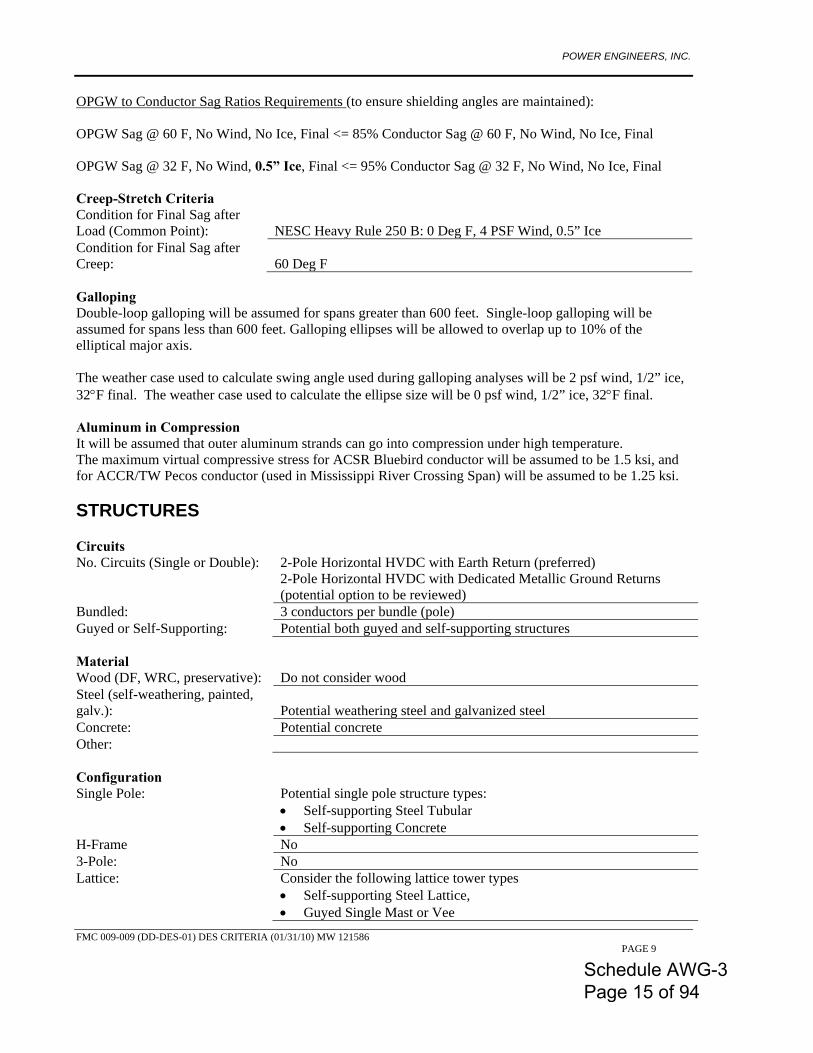
OPGW to Conductor Sag Ratios Requirements (to ensure shielding angles are maintained): OPGW Sag @ 60 F, No Wind, No Ice, Final <= 85% Conductor Sag @ 60 F, No Wind, No Ice, Final OPGW Sag @ 32 F, No Wind, 0.5” Ice, Final <= 95% Conductor Sag @ 32 F, No Wind, No Ice, Final Creep-Stretch Criteria Condition for Final Sag after Load (Common Point):
NESC Heavy Rule 250 B: 0 Deg F, 4 PSF Wind, 0.5” Ice
Condition for Final Sag after Creep:
60 Deg F
Galloping Double-loop galloping will be assumed for spans greater than 600 feet. Single-loop galloping will be assumed for spans less than 600 feet. Galloping ellipses will be allowed to overlap up to 10% of the elliptical major axis. The weather case used to calculate swing angle used during galloping analyses will be 2 psf wind, 1/2” ice, 32°F final. The weather case used to calculate the ellipse size will be 0 psf wind, 1/2” ice, 32°F final. Aluminum in Compression It will be assumed that outer aluminum strands can go into compression under high temperature. The maximum virtual compressive stress for ACSR Bluebird conductor will be assumed to be 1.5 ksi, and for ACCR/TW Pecos conductor (used in Mississippi River Crossing Span) will be assumed to be 1.25 ksi. STRUCTURES Circuits No. Circuits (Single or Double): 2-Pole Horizontal HVDC with Earth Return (preferred)
2-Pole Horizontal HVDC with Dedicated Metallic Ground Returns (potential option to be reviewed)
Bundled: 3 conductors per bundle (pole) Guyed or Self-Supporting: Potential both guyed and self-supporting structures Material Wood (DF, WRC, preservative): Do not consider wood Steel (self-weathering, painted, galv.):
Potential weathering steel and galvanized steel
Concrete: Potential concrete Other: Configuration Single Pole: Potential single pole structure types:
• Self-supporting Steel Tubular • Self-supporting Concrete
H-Frame No 3-Pole: No Lattice: Consider the following lattice tower types
• Self-supporting Steel Lattice, • Guyed Single Mast or Vee
Schedule AWG-3 Page 15 of 94
POWER ENGINEERS, INC.
FMC 009-009 (DD-DES-01) DES CRITERIA (01/31/10) MW 121586 PAGE 10
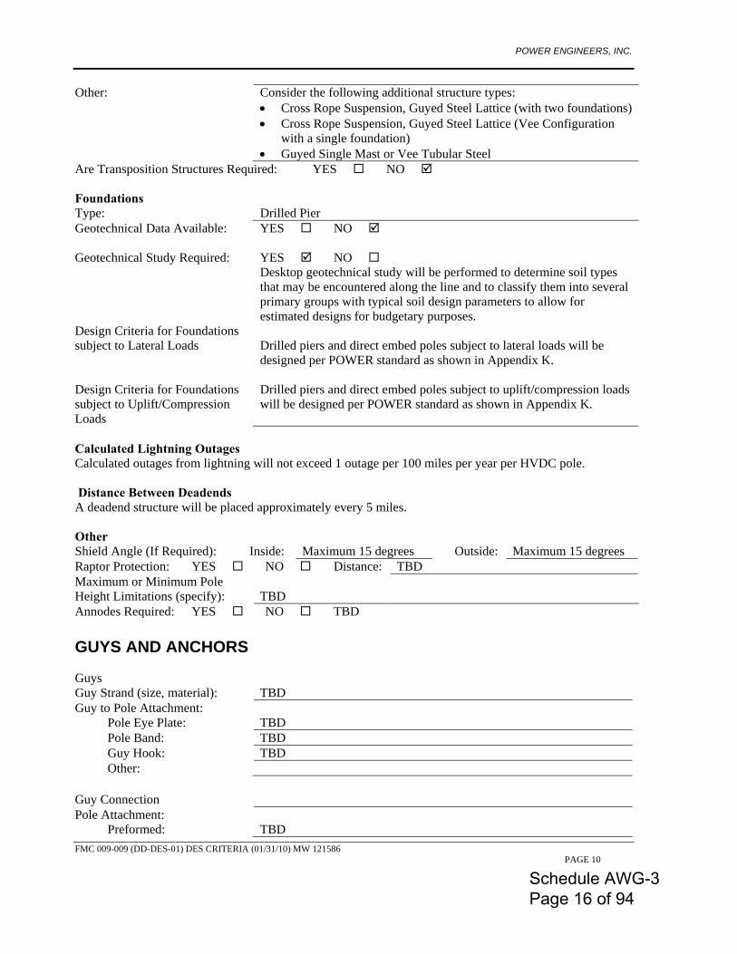
Other: Consider the following additional structure types: • Cross Rope Suspension, Guyed Steel Lattice (with two foundations) • Cross Rope Suspension, Guyed Steel Lattice (Vee Configuration
with a single foundation) • Guyed Single Mast or Vee Tubular Steel
Are Transposition Structures Required: YES NO Foundations Type: Drilled Pier Geotechnical Data Available: YES NO Geotechnical Study Required:
YES
NO
Design Criteria for Foundations subject to Lateral Loads
Desktop geotechnical study will be performed to determine soil types that may be encountered along the line and to classify them into several primary groups with typical soil design parameters to allow for estimated designs for budgetary purposes. Drilled piers and direct embed poles subject to lateral loads will be designed per POWER standard as shown in Appendix K.
Design Criteria for Foundations subject to Uplift/Compression Loads
Drilled piers and direct embed poles subject to uplift/compression loads will be designed per POWER standard as shown in Appendix K.
Calculated Lightning Outages Calculated outages from lightning will not exceed 1 outage per 100 miles per year per HVDC pole. Distance Between Deadends A deadend structure will be placed approximately every 5 miles. Other Shield Angle (If Required): Inside: Maximum 15 degrees Outside: Maximum 15 degrees Raptor Protection: YES NO Distance: TBD Maximum or Minimum Pole Height Limitations (specify):
TBD
Annodes Required: YES NO TBD GUYS AND ANCHORS Guys Guy Strand (size, material): TBD Guy to Pole Attachment:
Pole Eye Plate: TBD Pole Band: TBD Guy Hook: TBD Other:
Guy Connection Pole Attachment:
Preformed: TBD
Schedule AWG-3 Page 16 of 94
POWER ENGINEERS, INC.
FMC 009-009 (DD-DES-01) DES CRITERIA (01/31/10) MW 121586 PAGE 11
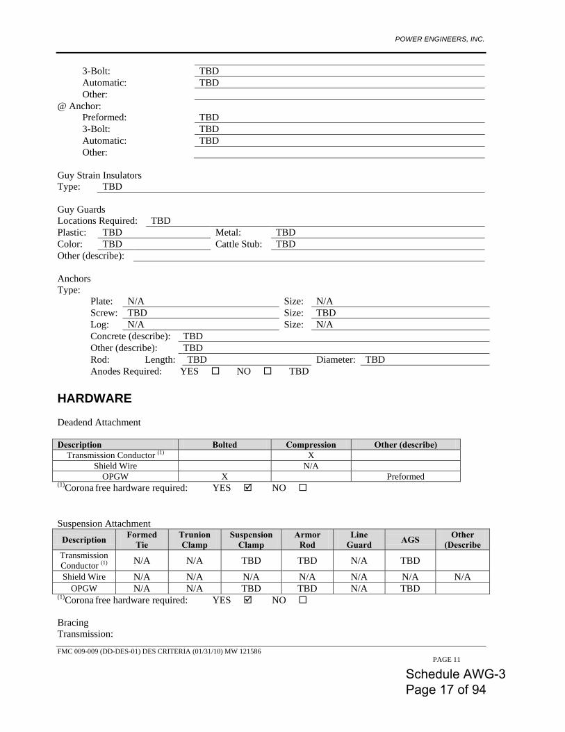
3-Bolt: TBD Automatic: TBD Other:
@ Anchor: Preformed: TBD 3-Bolt: TBD Automatic: TBD Other:
Guy Strain Insulators Type: TBD Guy Guards Locations Required: TBD Plastic: TBD Metal: TBD Color: TBD Cattle Stub: TBD Other (describe): Anchors Type:
Plate: N/A Size: N/A Screw: TBD Size: TBD Log: N/A Size: N/A Concrete (describe): TBD Other (describe): TBD Rod: Length: TBD Diameter: TBD Anodes Required: YES NO TBD
HARDWARE Deadend Attachment Description Bolted Compression Other (describe)
Transmission Conductor (1) X
Shield Wire N/A OPGW X Preformed
(1)Corona free hardware required: YES NO Suspension Attachment
Description Formed Tie
Trunion Clamp
Suspension Clamp
Armor Rod
Line Guard AGS Other
(Describe Transmission Conductor (1) N/A N/A TBD TBD N/A TBD Shield Wire N/A N/A N/A N/A N/A N/A N/A
OPGW N/A N/A TBD TBD N/A TBD (1)Corona free hardware required: YES NO Bracing Transmission:
Schedule AWG-3 Page 17 of 94
POWER ENGINEERS, INC.
FMC 009-009 (DD-DES-01) DES CRITERIA (01/31/10) MW 121586 PAGE 12
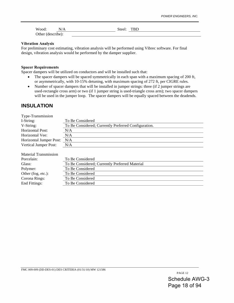
Wood: N/A Steel: TBD Other (describe):
Vibration Analysis For preliminary cost estimating, vibration analysis will be performed using Vibrec software. For final design, vibration analysis would be performed by the damper supplier. Spacer Requirements Spacer dampers will be utilized on conductors and will be installed such that:
• The spacer dampers will be spaced symmetrically in each span with a maximum spacing of 200 ft, or asymmetrically, with 10-15% detuning, with maximum spacing of 272 ft, per CIGRE rules.
• Number of spacer dampers that will be installed in jumper strings: three (if 2 jumper strings are used-rectangle cross arm) or two (if 1 jumper string is used-triangle cross arm); two spacer dampers will be used in the jumper loop. The spacer dampers will be equally spaced between the deadends.
INSULATION Type-Transmission I-String: To Be Considered V-String: To Be Considered; Currently Preferred Configuration. Horizontal Post: N/A Horizontal Vee: N/A Horizontal Jumper Post: N/A Vertical Jumper Post: N/A Material Transmission Porcelain: To Be Considered Glass: To Be Considered; Currently Preferred Material Polymer: To Be Considered Other (fog, etc.): To Be Considered Corona Rings: To Be Considered End Fittings: To Be Considered
Schedule AWG-3 Page 18 of 94
POWER ENGINEERS, INC.
FMC 009-009 (DD-DES-01) DES CRITERIA (01/31/10) MW 121586 PAGE 13
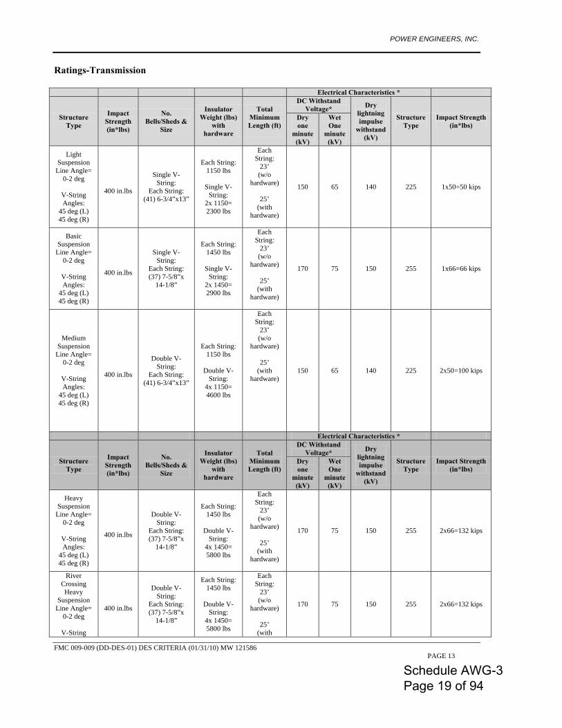
Ratings-Transmission
Electrical Characteristics *
Structure Type
Impact Strength (in*lbs)
No. Bells/Sheds &
Size
Insulator Weight (lbs)
with hardware
Total Minimum Length (ft)
DC Withstand Voltage* Dry
lightning impulse
withstand (kV)
Structure Type
Impact Strength (in*lbs)
Dry one
minute (kV)
Wet One
minute (kV)
Light Suspension
Line Angle= 0-2 deg
V-String Angles:
45 deg (L) 45 deg (R)
400 in.lbs
Single V-String:
Each String: (41) 6-3/4”x13”
Each String: 1150 lbs
Single V-
String: 2x 1150= 2300 lbs
Each String:
23’ (w/o
hardware)
25’ (with
hardware)
150 65 140 225 1x50=50 kips
Basic Suspension
Line Angle= 0-2 deg
V-String Angles:
45 deg (L) 45 deg (R)
400 in.lbs
Single V-String:
Each String: (37) 7-5/8”x
14-1/8”
Each String: 1450 lbs
Single V-
String: 2x 1450= 2900 lbs
Each String:
23’ (w/o
hardware)
25’ (with
hardware)
170 75 150 255 1x66=66 kips
Medium Suspension
Line Angle= 0-2 deg
V-String Angles:
45 deg (L) 45 deg (R)
400 in.lbs
Double V-String:
Each String: (41) 6-3/4”x13”
Each String: 1150 lbs
Double V-
String: 4x 1150= 4600 lbs
Each String:
23’ (w/o
hardware)
25’ (with
hardware)
150 65 140 225 2x50=100 kips
Electrical Characteristics *
Structure Type
Impact Strength (in*lbs)
No. Bells/Sheds &
Size
Insulator Weight (lbs)
with hardware
Total Minimum Length (ft)
DC Withstand Voltage* Dry
lightning impulse
withstand (kV)
Structure Type
Impact Strength (in*lbs)
Dry one
minute (kV)
Wet One
minute (kV)
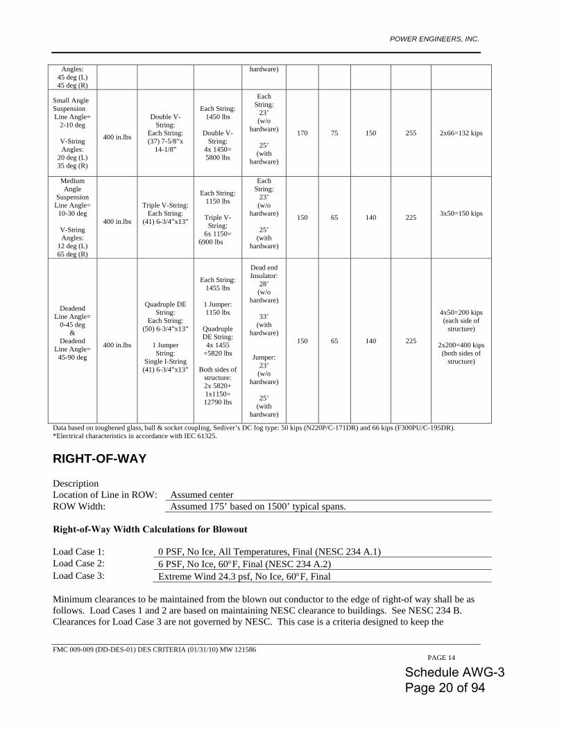
Heavy Suspension
Line Angle= 0-2 deg
V-String Angles:
45 deg (L) 45 deg (R)
400 in.lbs
Double V-String:
Each String: (37) 7-5/8”x
14-1/8”
Each String: 1450 lbs
Double V-
String: 4x 1450= 5800 lbs
Each String:
23’ (w/o
hardware)
25’ (with
hardware)
170 75 150 255 2x66=132 kips
River Crossing Heavy
Suspension Line Angle=
0-2 deg
V-String
400 in.lbs
Double V-String:
Each String: (37) 7-5/8”x
14-1/8”
Each String: 1450 lbs
Double V-
String: 4x 1450= 5800 lbs
Each String:
23’ (w/o
hardware)
25’ (with
170 75 150 255 2x66=132 kips
Schedule AWG-3 Page 19 of 94
POWER ENGINEERS, INC.
FMC 009-009 (DD-DES-01) DES CRITERIA (01/31/10) MW 121586 PAGE 14
Angles: 45 deg (L) 45 deg (R)
hardware)
Small Angle Suspension Line Angle=
2-10 deg
V-String Angles:
20 deg (L) 35 deg (R)
400 in.lbs
Double V-String:
Each String: (37) 7-5/8”x
14-1/8”
Each String: 1450 lbs
Double V-
String: 4x 1450= 5800 lbs
Each String:
23’ (w/o
hardware)
25’ (with
hardware)
170 75 150 255 2x66=132 kips
Medium Angle
Suspension Line Angle=
10-30 deg
V-String Angles:
12 deg (L) 65 deg (R)
400 in.lbs
Triple V-String: Each String:
(41) 6-3/4”x13”
Each String: 1150 lbs
Triple V-
String: 6x 1150=
6900 lbs
Each String:
23’ (w/o
hardware)
25’ (with
hardware)
150 65 140 225 3x50=150 kips
Deadend Line Angle=
0-45 deg &
Deadend Line Angle=
45-90 deg
400 in.lbs
Quadruple DE String:
Each String: (50) 6-3/4”x13”
1 Jumper String:
Single I-String (41) 6-3/4”x13”
Each String: 1455 lbs
1 Jumper: 1150 lbs
Quadruple DE String:
4x 1455 =5820 lbs
Both sides of
structure: 2x 5820+ 1x1150= 12790 lbs
Dead end Insulator:
28’ (w/o
hardware)
33’ (with
hardware)
Jumper: 23’ (w/o
hardware)
25’ (with
hardware)
150 65 140 225
4x50=200 kips (each side of
structure)
2x200=400 kips (both sides of
structure)
Data based on toughened glass, ball & socket coupling, Sediver’s DC fog type: 50 kips (N220P/C-171DR) and 66 kips (F300PU/C-195DR). *Electrical characteristics in accordance with IEC 61325. RIGHT-OF-WAY Description Location of Line in ROW: Assumed center ROW Width: Assumed 175’ based on 1500’ typical spans. Right-of-Way Width Calculations for Blowout Load Case 1: 0 PSF, No Ice, All Temperatures, Final (NESC 234 A.1) Load Case 2: 6 PSF, No Ice, 60°F, Final (NESC 234 A.2) Load Case 3: Extreme Wind 24.3 psf, No Ice, 60°F, Final Minimum clearances to be maintained from the blown out conductor to the edge of right-of way shall be as follows. Load Cases 1 and 2 are based on maintaining NESC clearance to buildings. See NESC 234 B. Clearances for Load Case 3 are not governed by NESC. This case is a criteria designed to keep the
Schedule AWG-3 Page 20 of 94
POWER ENGINEERS, INC.
FMC 009-009 (DD-DES-01) DES CRITERIA (01/31/10) MW 121586 PAGE 15
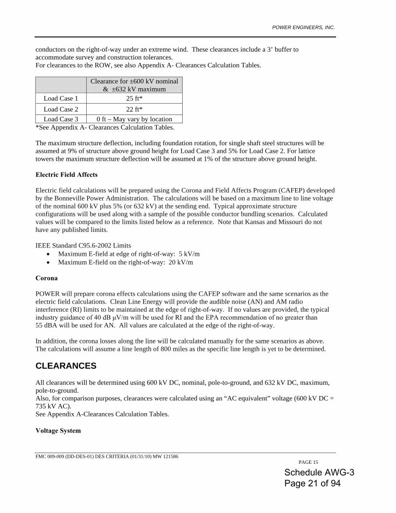
conductors on the right-of-way under an extreme wind. These clearances include a 3’ buffer to accommodate survey and construction tolerances. For clearances to the ROW, see also Appendix A- Clearances Calculation Tables.
Clearance for ±600 kV nominal & ±632 kV maximum
Load Case 1 25 ft* Load Case 2 22 ft* Load Case 3 0 ft – May vary by location
*See Appendix A- Clearances Calculation Tables. The maximum structure deflection, including foundation rotation, for single shaft steel structures will be assumed at 9% of structure above ground height for Load Case 3 and 5% for Load Case 2. For lattice towers the maximum structure deflection will be assumed at 1% of the structure above ground height. Electric Field Affects Electric field calculations will be prepared using the Corona and Field Affects Program (CAFEP) developed by the Bonneville Power Administration. The calculations will be based on a maximum line to line voltage of the nominal 600 kV plus 5% (or 632 kV) at the sending end. Typical approximate structure configurations will be used along with a sample of the possible conductor bundling scenarios. Calculated values will be compared to the limits listed below as a reference. Note that Kansas and Missouri do not have any published limits. IEEE Standard C95.6-2002 Limits
• Maximum E-field at edge of right-of-way: 5 kV/m • Maximum E-field on the right-of-way: 20 kV/m
Corona POWER will prepare corona effects calculations using the CAFEP software and the same scenarios as the electric field calculations. Clean Line Energy will provide the audible noise (AN) and AM radio interference (RI) limits to be maintained at the edge of right-of-way. If no values are provided, the typical industry guidance of 40 dB μV/m will be used for RI and the EPA recommendation of no greater than 55 dBA will be used for AN. All values are calculated at the edge of the right-of-way. In addition, the corona losses along the line will be calculated manually for the same scenarios as above. The calculations will assume a line length of 800 miles as the specific line length is yet to be determined. CLEARANCES All clearances will be determined using 600 kV DC, nominal, pole-to-ground, and 632 kV DC, maximum, pole-to-ground. Also, for comparison purposes, clearances were calculated using an “AC equivalent” voltage (600 kV DC = 735 kV AC). See Appendix A-Clearances Calculation Tables. Voltage System
Schedule AWG-3 Page 21 of 94
POWER ENGINEERS, INC.
FMC 009-009 (DD-DES-01) DES CRITERIA (01/31/10) MW 121586 PAGE 16
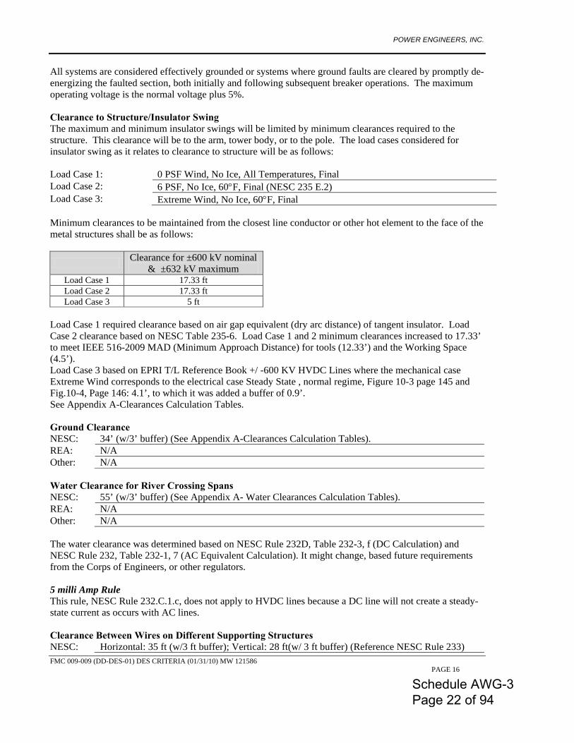
All systems are considered effectively grounded or systems where ground faults are cleared by promptly de-energizing the faulted section, both initially and following subsequent breaker operations. The maximum operating voltage is the normal voltage plus 5%. Clearance to Structure/Insulator Swing The maximum and minimum insulator swings will be limited by minimum clearances required to the structure. This clearance will be to the arm, tower body, or to the pole. The load cases considered for insulator swing as it relates to clearance to structure will be as follows: Load Case 1: 0 PSF Wind, No Ice, All Temperatures, Final Load Case 2: 6 PSF, No Ice, 60°F, Final (NESC 235 E.2) Load Case 3: Extreme Wind, No Ice, 60°F, Final Minimum clearances to be maintained from the closest line conductor or other hot element to the face of the metal structures shall be as follows:
Clearance for ±600 kV nominal & ±632 kV maximum
Load Case 1 17.33 ft Load Case 2 17.33 ft Load Case 3 5 ft
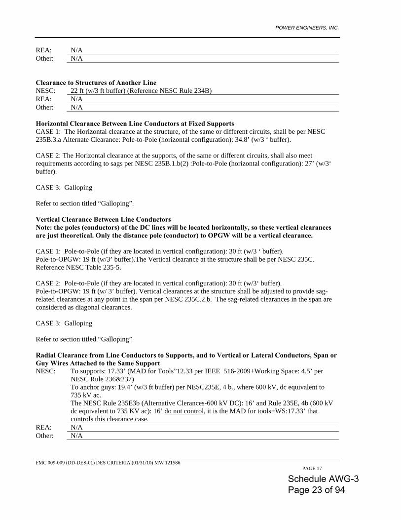
Load Case 1 required clearance based on air gap equivalent (dry arc distance) of tangent insulator. Load Case 2 clearance based on NESC Table 235-6. Load Case 1 and 2 minimum clearances increased to 17.33’ to meet IEEE 516-2009 MAD (Minimum Approach Distance) for tools (12.33’) and the Working Space (4.5’). Load Case 3 based on EPRI T/L Reference Book +/ -600 KV HVDC Lines where the mechanical case Extreme Wind corresponds to the electrical case Steady State , normal regime, Figure 10-3 page 145 and Fig.10-4, Page 146: 4.1’, to which it was added a buffer of 0.9’. See Appendix A-Clearances Calculation Tables. Ground Clearance NESC: 34’ (w/3’ buffer) (See Appendix A-Clearances Calculation Tables). REA: N/A Other: N/A Water Clearance for River Crossing Spans NESC: 55’ (w/3’ buffer) (See Appendix A- Water Clearances Calculation Tables). REA: N/A Other: N/A The water clearance was determined based on NESC Rule 232D, Table 232-3, f (DC Calculation) and NESC Rule 232, Table 232-1, 7 (AC Equivalent Calculation). It might change, based future requirements from the Corps of Engineers, or other regulators. 5 milli Amp Rule This rule, NESC Rule 232.C.1.c, does not apply to HVDC lines because a DC line will not create a steady-state current as occurs with AC lines. Clearance Between Wires on Different Supporting Structures NESC: Horizontal: 35 ft (w/3 ft buffer); Vertical: 28 ft(w/ 3 ft buffer) (Reference NESC Rule 233)
Schedule AWG-3 Page 22 of 94
POWER ENGINEERS, INC.
FMC 009-009 (DD-DES-01) DES CRITERIA (01/31/10) MW 121586 PAGE 17
REA: N/A Other: N/A Clearance to Structures of Another Line NESC: 22 ft (w/3 ft buffer) (Reference NESC Rule 234B) REA: N/A Other: N/A Horizontal Clearance Between Line Conductors at Fixed Supports CASE 1: The Horizontal clearance at the structure, of the same or different circuits, shall be per NESC 235B.3.a Alternate Clearance: Pole-to-Pole (horizontal configuration): 34.8’ (w/3 ‘ buffer). CASE 2: The Horizontal clearance at the supports, of the same or different circuits, shall also meet requirements according to sags per NESC 235B.1.b(2) :Pole-to-Pole (horizontal configuration): 27’ (w/3‘ buffer). CASE 3: Galloping Refer to section titled “Galloping”. Vertical Clearance Between Line Conductors Note: the poles (conductors) of the DC lines will be located horizontally, so these vertical clearances are just theoretical. Only the distance pole (conductor) to OPGW will be a vertical clearance. CASE 1: Pole-to-Pole (if they are located in vertical configuration): 30 ft (w/3 ‘ buffer). Pole-to-OPGW: 19 ft (w/3’ buffer).The Vertical clearance at the structure shall be per NESC 235C. Reference NESC Table 235-5. CASE 2: Pole-to-Pole (if they are located in vertical configuration): 30 ft (w/3‘ buffer). Pole-to-OPGW: 19 ft (w/ 3’ buffer). Vertical clearances at the structure shall be adjusted to provide sag-related clearances at any point in the span per NESC 235C.2.b. The sag-related clearances in the span are considered as diagonal clearances. CASE 3: Galloping Refer to section titled “Galloping”. Radial Clearance from Line Conductors to Supports, and to Vertical or Lateral Conductors, Span or Guy Wires Attached to the Same Support NESC: To supports: 17.33’ (MAD for Tools”12.33 per IEEE 516-2009+Working Space: 4.5’ per
NESC Rule 236&237) To anchor guys: 19.4’ (w/3 ft buffer) per NESC235E, 4 b., where 600 kV, dc equivalent to 735 kV ac. The NESC Rule 235E3b (Alternative Clerances-600 kV DC): 16’ and Rule 235E, 4b (600 kV dc equivalent to 735 KV ac): 16’ do not control, it is the MAD for tools+WS:17.33’ that controls this clearance case.
REA: N/A Other: N/A
Schedule AWG-3 Page 23 of 94
POWER ENGINEERS, INC.
FMC 009-009 (DD-DES-01) DES CRITERIA (01/31/10) MW 121586 PAGE 18
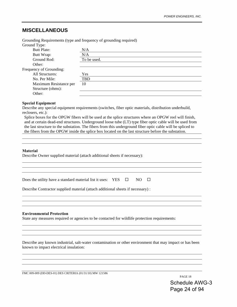
MISCELLANEOUS Grounding Requirements (type and frequency of grounding required) Ground Type:
Butt Plate: N/A Butt Wrap: N/A Ground Rod: To be used. Other:
Frequency of Grounding: All Structures: Yes No. Per Mile: TBD Maximum Resistance per Structure (ohms):
10
Other: Special Equipment Describe any special equipment requirements (switches, fiber optic materials, distribution underbuild, reclosers, etc.): Splice boxes for the OPGW fibers will be used at the splice structures where an OPGW reel will finish, and at certain dead-end structures. Underground loose tube (LT) type fiber optic cable will be used from the last structure to the substation. The fibers from this underground fiber optic cable will be spliced to the fibers from the OPGW inside the splice box located on the last structure before the substation.
Material Describe Owner supplied material (attach additional sheets if necessary):
Does the utility have a standard material list it uses: YES NO Describe Contractor supplied material (attach additional sheets if necessary) :
Environmental Protection State any measures required or agencies to be contacted for wildlife protection requirements:
Describe any known industrial, salt-water contamination or other environment that may impact or has been known to impact electrical insulation:
Schedule AWG-3 Page 24 of 94

POWER ENGINEERS, INC.
FMC 009-009 (DD-DES-01) DES CRITERIA (01/31/10) MW 121586 PAGE 19
State any measures required for airborne contamination protection (dust control):
Describe any known caustic or corrosive soil conditions:
DRAWINGS AND MAPS Maps Existing facility maps, P&P’s available: YES NO List foreign utilities to be considered for project, if maps are available: Power: Gas: Phone: TV: Sewer: Water: Highways: Railroad: Other: Separate access road maps required: YES NO Describe ROW/Environmental or Easement Maps required, if any:
Drawing Requirements Map and Plan and Profile Scales:
Key Map Scale:
horiz.
Plan Scale: horiz. Profile Scale: vert. Size: horiz.
Plan Type: Planimetric: Topographic: Other:
Title Block: POWER Standard: Other:
Drawing Numbers: POWER Generated: Owner Generated (describe):
Final Drawings:
Schedule AWG-3 Page 25 of 94
POWER ENGINEERS, INC.
FMC 009-009 (DD-DES-01) DES CRITERIA (01/31/10) MW 121586 PAGE 20
Describe structure numbering sequence:
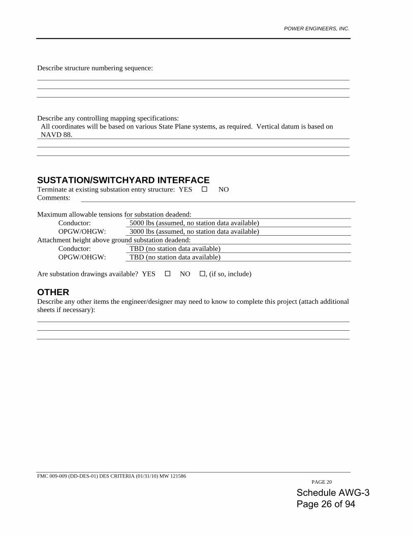
Describe any controlling mapping specifications: All coordinates will be based on various State Plane systems, as required. Vertical datum is based on NAVD 88.
SUSTATION/SWITCHYARD INTERFACE Terminate at existing substation entry structure: YES NO Comments: Maximum allowable tensions for substation deadend:
Conductor: 5000 lbs (assumed, no station data available) OPGW/OHGW: 3000 lbs (assumed, no station data available)
Attachment height above ground substation deadend: Conductor: TBD (no station data available) OPGW/OHGW: TBD (no station data available)
Are substation drawings available? YES NO , (if so, include) OTHER Describe any other items the engineer/designer may need to know to complete this project (attach additional sheets if necessary):
Schedule AWG-3 Page 26 of 94
POWER ENGINEERS, INC.
FMC 009-009 (DD-DES-01) DES CRITERIA (01/31/10) MW 121586 PAGE 21
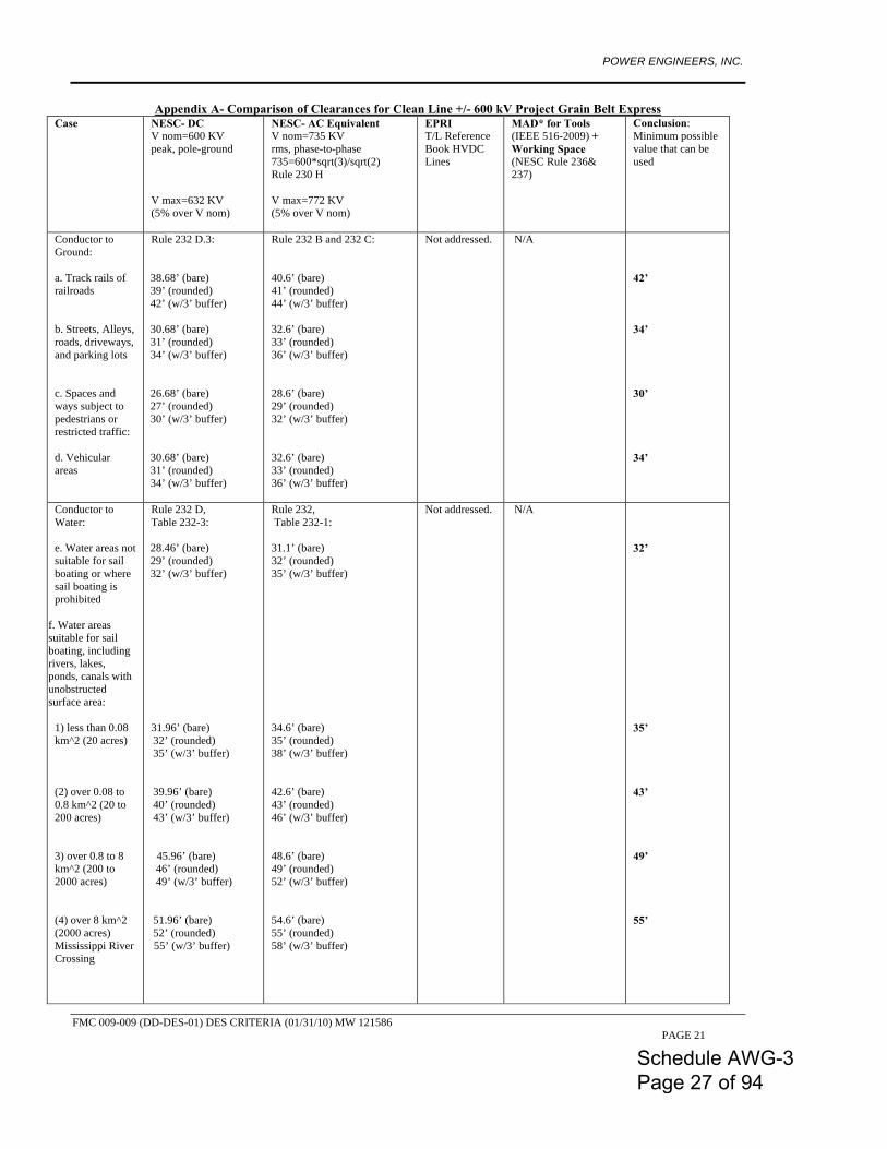
Appendix A- Comparison of Clearances for Clean Line +/- 600 kV Project Grain Belt Express Case NESC- DC
V nom=600 KV peak, pole-ground V max=632 KV (5% over V nom)
NESC- AC Equivalent V nom=735 KV rms, phase-to-phase 735=600*sqrt(3)/sqrt(2) Rule 230 H V max=772 KV (5% over V nom)
EPRI T/L Reference Book HVDC Lines
MAD* for Tools (IEEE 516-2009) + Working Space (NESC Rule 236& 237)
Conclusion: Minimum possible value that can be used
Conductor to Ground: a. Track rails of railroads b. Streets, Alleys, roads, driveways, and parking lots c. Spaces and ways subject to pedestrians or restricted traffic: d. Vehicular areas
Rule 232 D.3:
38.68’ (bare) 39’ (rounded) 42’ (w/3’ buffer)
30.68’ (bare) 31’ (rounded) 34’ (w/3’ buffer)
26.68’ (bare) 27’ (rounded) 30’ (w/3’ buffer)
30.68’ (bare) 31’ (rounded) 34’ (w/3’ buffer)
Rule 232 B and 232 C: 40.6’ (bare) 41’ (rounded) 44’ (w/3’ buffer) 32.6’ (bare) 33’ (rounded) 36’ (w/3’ buffer) 28.6’ (bare) 29’ (rounded) 32’ (w/3’ buffer) 32.6’ (bare) 33’ (rounded) 36’ (w/3’ buffer)
Not addressed. N/A 42’ 34’ 30’ 34’
Conductor to Water: e. Water areas not suitable for sail boating or where sail boating is prohibited
f. Water areas suitable for sail boating, including rivers, lakes, ponds, canals with unobstructed surface area:
1) less than 0.08 km^2 (20 acres) (2) over 0.08 to 0.8 km^2 (20 to 200 acres) 3) over 0.8 to 8 km^2 (200 to 2000 acres) (4) over 8 km^2 (2000 acres) Mississippi River Crossing
Rule 232 D, Table 232-3:
28.46’ (bare) 29’ (rounded) 32’ (w/3’ buffer)
31.96’ (bare) 32’ (rounded) 35’ (w/3’ buffer)
39.96’ (bare) 40’ (rounded) 43’ (w/3’ buffer)
45.96’ (bare)
46’ (rounded) 49’ (w/3’ buffer)
51.96’ (bare) 52’ (rounded)
55’ (w/3’ buffer)
Rule 232, Table 232-1: 31.1’ (bare) 32’ (rounded) 35’ (w/3’ buffer)
34.6’ (bare) 35’ (rounded) 38’ (w/3’ buffer) 42.6’ (bare) 43’ (rounded) 46’ (w/3’ buffer) 48.6’ (bare) 49’ (rounded) 52’ (w/3’ buffer)
54.6’ (bare) 55’ (rounded) 58’ (w/3’ buffer)
Not addressed. N/A 32’ 35’ 43’ 49’ 55’
Schedule AWG-3 Page 27 of 94
POWER ENGINEERS, INC.
FMC 009-009 (DD-DES-01) DES CRITERIA (01/31/10) MW 121586 PAGE 22
Case NESC- DC
V nom=600 KV peak, pole-ground V max=632 KV (5% over V nom)
NESC- AC Equivalent V nom=735 KV rms, phase-to-phase 735=600*sqrt(3)/sqrt(2) Rule 230 H V max=772 KV (5% over V nom)
EPRI T/L Reference Book HVDC Lines
MAD* for Tools (IEEE 516-2009) + Working Space (NESC Rule 236& 237)
Conclusion: Minimum possible value that can be used
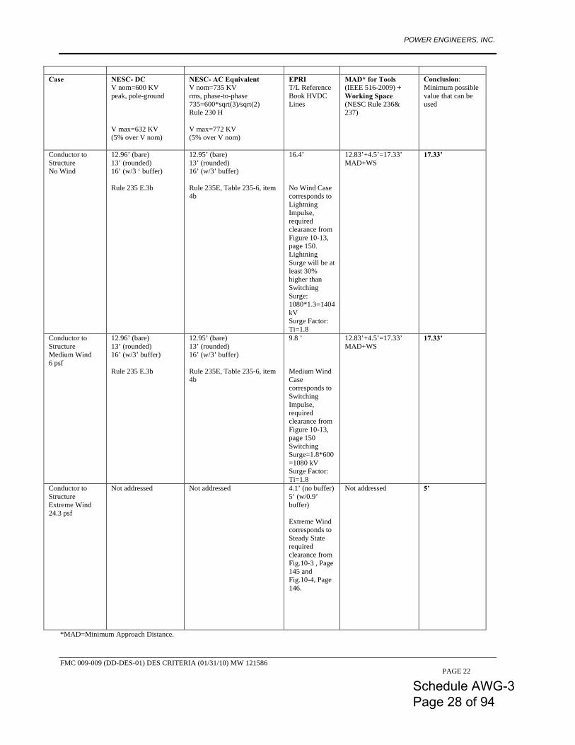
Conductor to Structure No Wind
12.96’ (bare) 13’ (rounded) 16’ (w/3 ‘ buffer) Rule 235 E.3b
12.95’ (bare) 13’ (rounded) 16’ (w/3’ buffer) Rule 235E, Table 235-6, item 4b
16.4’ No Wind Case corresponds to Lightning Impulse, required clearance from Figure 10-13, page 150. Lightning Surge will be at least 30% higher than Switching Surge: 1080*1.3=1404 kV Surge Factor: Ti=1.8
12.83’+4.5’=17.33’ MAD+WS
17.33’
Conductor to Structure Medium Wind 6 psf
12.96’ (bare) 13’ (rounded) 16’ (w/3’ buffer) Rule 235 E.3b
12.95’ (bare) 13’ (rounded) 16’ (w/3’ buffer) Rule 235E, Table 235-6, item 4b
9.8 ’ Medium Wind Case corresponds to Switching Impulse, required clearance from Figure 10-13, page 150 Switching Surge=1.8*600 =1080 kV Surge Factor: Ti=1.8
12.83’+4.5’=17.33’ MAD+WS
17.33’
Conductor to Structure Extreme Wind 24.3 psf
Not addressed Not addressed 4.1’ (no buffer) 5’ (w/0.9’ buffer) Extreme Wind corresponds to Steady State required clearance from Fig.10-3 , Page 145 and Fig.10-4, Page 146.
Not addressed 5’
*MAD=Minimum Approach Distance.
Schedule AWG-3 Page 28 of 94
POWER ENGINEERS, INC.
FMC 009-009 (DD-DES-01) DES CRITERIA (01/31/10) MW 121586 PAGE 23
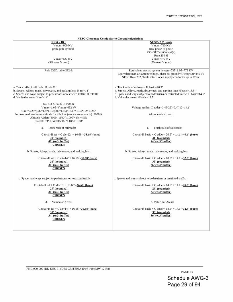
NESC-Clearance Conductor to Ground calculation: NESC- DC:
V nom=600 KV peak, pole-ground
V max=632 KV (5% over V nom)
NESC- AC Equiv V nom=735 KV
rms, phase-to-phase 735=600*sqrt(3)/sqrt(2)
Rule 230 H V max=772 KV
(5% over V nom)
Rule 232D, table 232-3:
a. a. Track rails of railroads: H ref=22’
b. Streets, Alleys, roads, driveways, and parking lots: H ref=14’ c. Spaces and ways subject to pedestrians or restricted traffic: H ref=10’ d. Vehicular areas: H ref=14’
For Ref Altitude < 1500 ft:
V max=1.05*V nom=632 kV C ref=3.28*(632*1.8*1.15/(500*1.15)^1.667*1.03*1.2=15.96’
For assumed maximum altitude for this line (worst case scenario): 3000 ft: Altitude Adder: (3000’-1500’)/1000’*3%=4.5%
C alt=C ref*1.045=15.96’*1.045=16.68’
a. Track rails of railroads: C total=H ref + C alt=22’ + 16.68’=38.68’ (bare)
39’ (rounded) 42’ (w/3’ buffer)
CHOSEN
b. Streets, Alleys, roads, driveways, and parking lots:
C total=H ref + C alt=14’ + 16.68’=30.68’ (bare) 31’ (rounded)
34’ (w/3’ buffer) CHOSEN
b. c. Spaces and ways subject to pedestrians or restricted traffic:
C total=H ref + C alt=10’ + 16.68’=26.68’ (bare) 27’ (rounded)
30’ (w/3’ buffer) CHOSEN
d. Vehicular Areas:
C total=H ref + C alt=14’ + 16.68’=30.68’ (bare)
31’ (rounded) 34’ (w/3’ buffer)
CHOSEN
Equivalent max ac system voltage=735*1.05=772 KV Equivalent max ac system voltage, phase-to-ground=772/sqrt(3)=446 kV
NESC Rule 232, Table 232-1, open supply conductor up to 22 kv:
a. Track rails of railroads: H basic=26.5’ b. Streets, Alleys, roads, driveways, and parking lots: H basic=18.5’ c. Spaces and ways subject to pedestrians or restricted traffic: H basic=14.5’
e. d. Vehicular areas: H basic=18.5’
Voltage Adder: C adder=(446-22)*0.4”/12=14.1’
Altitude adder : zero
a. Track rails of railroads:
C total=H basic + C adder= 26.5’ + 14.1’=40.6’ (bare)
41’ (rounded) 44’ (w/3’ buffer)
b. Streets, Alleys, roads, driveways, and parking lots:
C total=H basic + C adder= 18.5’ + 14.1’=32.6’ (bare) 33’ (rounded)
36’ (w/3’ buffer) f. g. h. i. c. Spaces and ways subject to pedestrians or restricted traffic :
C total=H basic + C adder= 14.5’ + 14.1’=28.6’ (bare)
29’ (rounded) 32’ (w/3’ buffer)
j. d. Vehicular Areas:
C total=H basic + C adder= 18.5’ + 14.1’=32.6’ (bare) 33’ (rounded)
36’ (w/3’ buffer)
Schedule AWG-3 Page 29 of 94
POWER ENGINEERS, INC.
FMC 009-009 (DD-DES-01) DES CRITERIA (01/31/10) MW 121586 PAGE 24
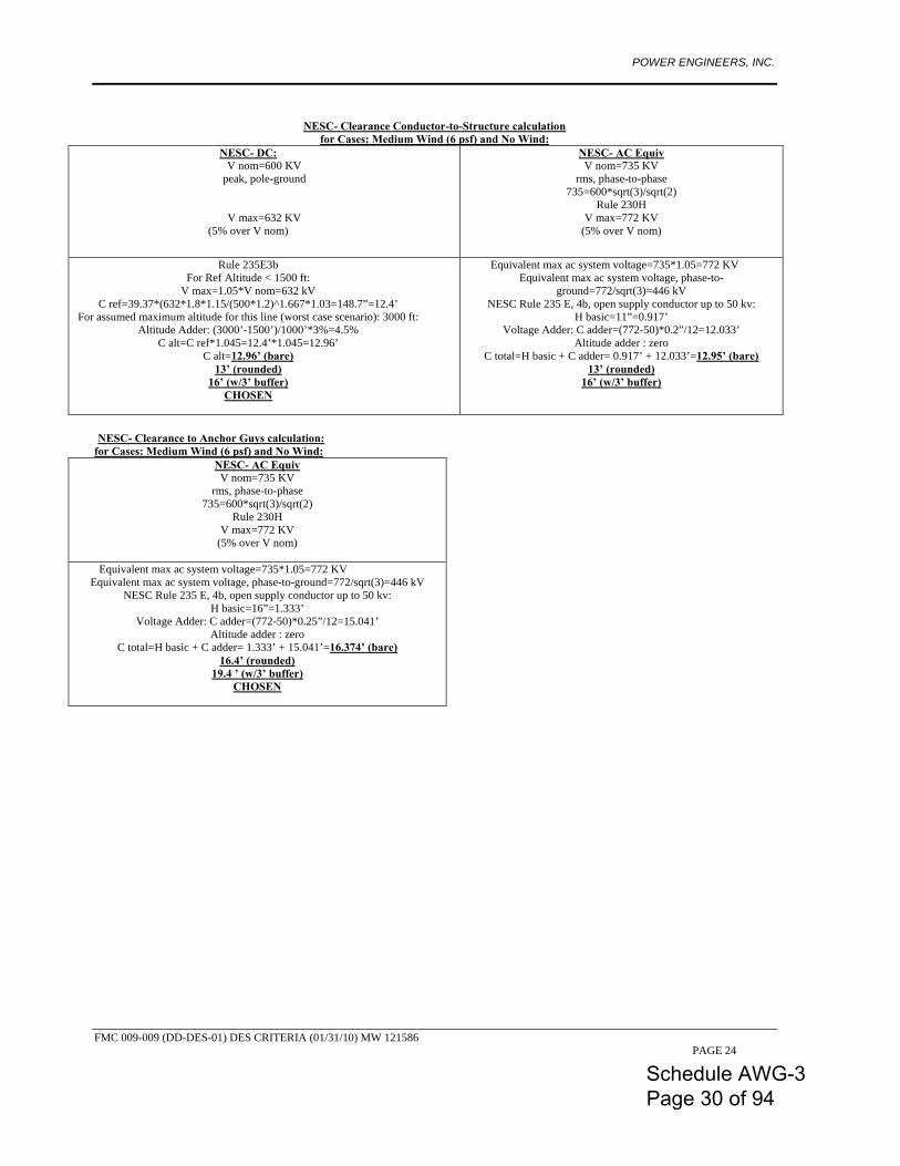
NESC- Clearance Conductor-to-Structure calculation
for Cases: Medium Wind (6 psf) and No Wind: NESC- DC:
V nom=600 KV peak, pole-ground
V max=632 KV (5% over V nom)
NESC- AC Equiv V nom=735 KV
rms, phase-to-phase 735=600*sqrt(3)/sqrt(2)
Rule 230H V max=772 KV
(5% over V nom)
Rule 235E3b For Ref Altitude < 1500 ft:
V max=1.05*V nom=632 kV C ref=39.37*(632*1.8*1.15/(500*1.2)^1.667*1.03=148.7”=12.4’
For assumed maximum altitude for this line (worst case scenario): 3000 ft: Altitude Adder: (3000’-1500’)/1000’*3%=4.5%
C alt=C ref*1.045=12.4’*1.045=12.96’ C alt=12.96’ (bare)
13’ (rounded) 16’ (w/3’ buffer)
CHOSEN
Equivalent max ac system voltage=735*1.05=772 KV Equivalent max ac system voltage, phase-to-
ground=772/sqrt(3)=446 kV NESC Rule 235 E, 4b, open supply conductor up to 50 kv:
H basic=11”=0.917’ Voltage Adder: C adder=(772-50)*0.2”/12=12.033’
Altitude adder : zero C total=H basic + C adder= 0.917’ + 12.033’=12.95’ (bare)
13’ (rounded) 16’ (w/3’ buffer)
NESC- Clearance to Anchor Guys calculation: for Cases: Medium Wind (6 psf) and No Wind:
NESC- AC Equiv V nom=735 KV
rms, phase-to-phase 735=600*sqrt(3)/sqrt(2)
Rule 230H V max=772 KV
(5% over V nom)
Equivalent max ac system voltage=735*1.05=772 KV Equivalent max ac system voltage, phase-to-ground=772/sqrt(3)=446 kV
NESC Rule 235 E, 4b, open supply conductor up to 50 kv: H basic=16”=1.333’
Voltage Adder: C adder=(772-50)*0.25”/12=15.041’ Altitude adder : zero
C total=H basic + C adder= 1.333’ + 15.041’=16.374’ (bare) 16.4’ (rounded)
19.4 ’ (w/3’ buffer) CHOSEN
Schedule AWG-3 Page 30 of 94
POWER ENGINEERS, INC.
FMC 009-009 (DD-DES-01) DES CRITERIA (01/31/10) MW 121586 PAGE 25
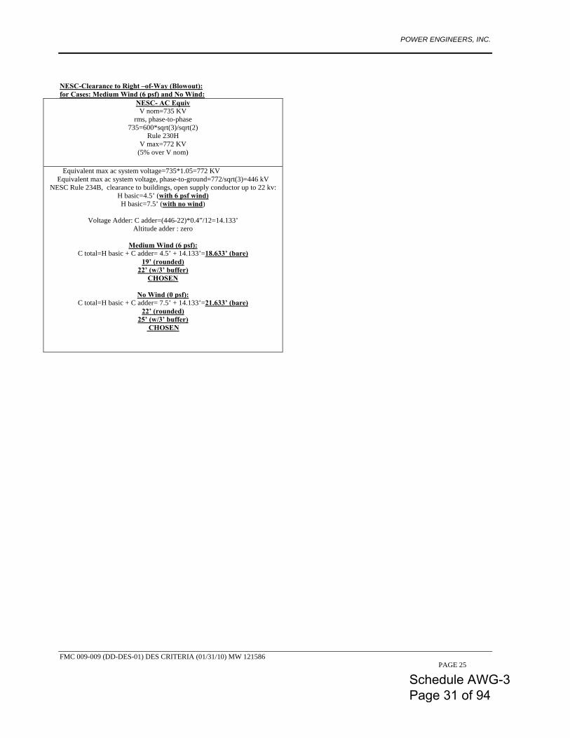
NESC-Clearance to Right –of-Way (Blowout): for Cases: Medium Wind (6 psf) and No Wind:
NESC- AC Equiv V nom=735 KV
rms, phase-to-phase 735=600*sqrt(3)/sqrt(2)
Rule 230H V max=772 KV
(5% over V nom)
Equivalent max ac system voltage=735*1.05=772 KV Equivalent max ac system voltage, phase-to-ground=772/sqrt(3)=446 kV
NESC Rule 234B, clearance to buildings, open supply conductor up to 22 kv: H basic=4.5’ (with 6 psf wind) H basic=7.5’ (with no wind)
Voltage Adder: C adder=(446-22)*0.4”/12=14.133’
Altitude adder : zero
Medium Wind (6 psf): C total=H basic + C adder= 4.5’ + 14.133’=18.633’ (bare)
19’ (rounded) 22’ (w/3’ buffer)
CHOSEN
No Wind (0 psf): C total=H basic + C adder= 7.5’ + 14.133’=21.633’ (bare)
22’ (rounded) 25’ (w/3’ buffer)
CHOSEN
Schedule AWG-3 Page 31 of 94
POWER ENGINEERS, INC.
FMC 009-009 (DD-DES-01) DES CRITERIA (01/31/10) MW 121586 PAGE 26
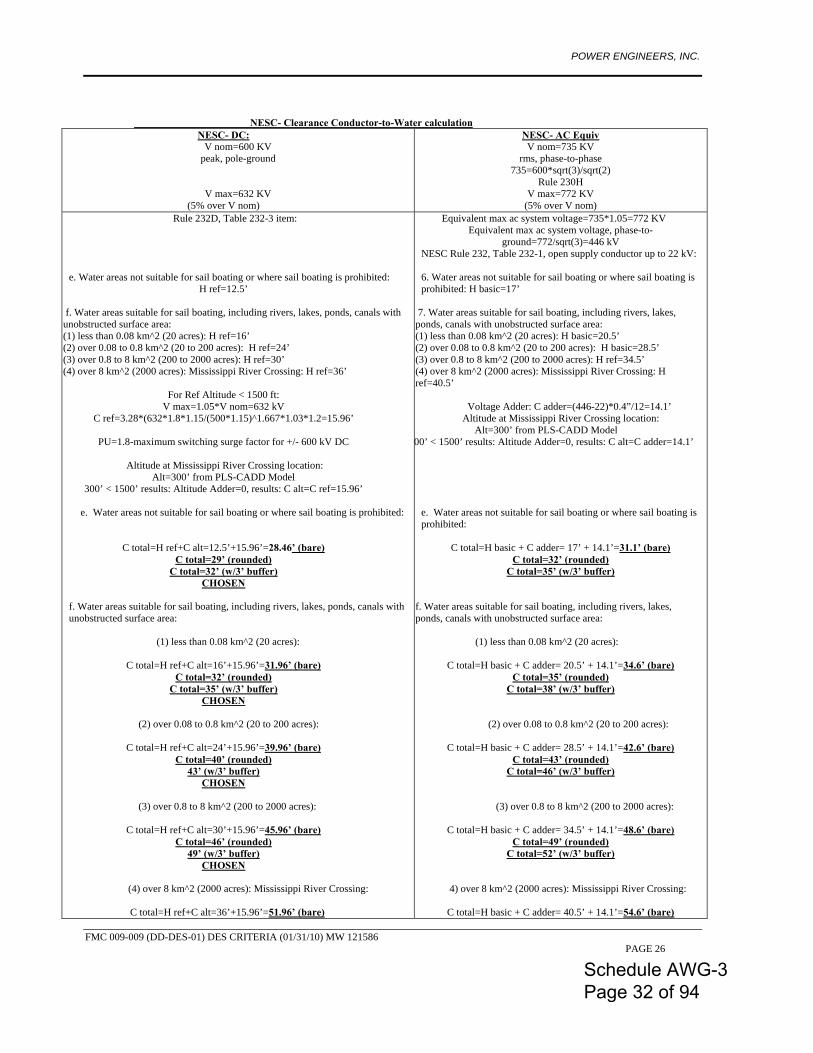
NESC- Clearance Conductor-to-Water calculation NESC- DC:
V nom=600 KV peak, pole-ground
V max=632 KV (5% over V nom)
NESC- AC Equiv V nom=735 KV
rms, phase-to-phase 735=600*sqrt(3)/sqrt(2)
Rule 230H V max=772 KV
(5% over V nom) Rule 232D, Table 232-3 item:
e. Water areas not suitable for sail boating or where sail boating is prohibited:
H ref=12.5’
f. Water areas suitable for sail boating, including rivers, lakes, ponds, canals with unobstructed surface area: (1) less than 0.08 km^2 (20 acres): H ref=16’ (2) over 0.08 to 0.8 km^2 (20 to 200 acres): H ref=24’ (3) over 0.8 to 8 km^2 (200 to 2000 acres): H ref=30’ (4) over 8 km^2 (2000 acres): Mississippi River Crossing: H ref=36’
For Ref Altitude < 1500 ft: V max=1.05*V nom=632 kV
C ref=3.28*(632*1.8*1.15/(500*1.15)^1.667*1.03*1.2=15.96’
PU=1.8-maximum switching surge factor for +/- 600 kV DC
Altitude at Mississippi River Crossing location: Alt=300’ from PLS-CADD Model
300’ < 1500’ results: Altitude Adder=0, results: C alt=C ref=15.96’
e. e. Water areas not suitable for sail boating or where sail boating is prohibited:
C total=H ref+C alt=12.5’+15.96’=28.46’ (bare) C total=29’ (rounded)
C total=32’ (w/3’ buffer) CHOSEN
f. Water areas suitable for sail boating, including rivers, lakes, ponds, canals with unobstructed surface area: (1) less than 0.08 km^2 (20 acres):
C total=H ref+C alt=16’+15.96’=31.96’ (bare)
C total=32’ (rounded) C total=35’ (w/3’ buffer)
CHOSEN (2) over 0.08 to 0.8 km^2 (20 to 200 acres):
C total=H ref+C alt=24’+15.96’=39.96’ (bare) C total=40’ (rounded)
43’ (w/3’ buffer) CHOSEN
(3) over 0.8 to 8 km^2 (200 to 2000 acres):
C total=H ref+C alt=30’+15.96’=45.96’ (bare) C total=46’ (rounded)
49’ (w/3’ buffer) CHOSEN
(4) over 8 km^2 (2000 acres): Mississippi River Crossing:
C total=H ref+C alt=36’+15.96’=51.96’ (bare)
Equivalent max ac system voltage=735*1.05=772 KV Equivalent max ac system voltage, phase-to-
ground=772/sqrt(3)=446 kV NESC Rule 232, Table 232-1, open supply conductor up to 22 kV:
6. Water areas not suitable for sail boating or where sail boating is prohibited: H basic=17’
7. Water areas suitable for sail boating, including rivers, lakes, ponds, canals with unobstructed surface area: (1) less than 0.08 km^2 (20 acres): H basic=20.5’ (2) over 0.08 to 0.8 km^2 (20 to 200 acres): H basic=28.5’ (3) over 0.8 to 8 km^2 (200 to 2000 acres): H ref=34.5’ (4) over 8 km^2 (2000 acres): Mississippi River Crossing: H ref=40.5’
Voltage Adder: C adder=(446-22)*0.4”/12=14.1’ Altitude at Mississippi River Crossing location:
Alt=300’ from PLS-CADD Model 300’ < 1500’ results: Altitude Adder=0, results: C alt=C adder=14.1’
e. Water areas not suitable for sail boating or where sail boating is prohibited:
C total=H basic + C adder= 17’ + 14.1’=31.1’ (bare)
C total=32’ (rounded) C total=35’ (w/3’ buffer)
f. Water areas suitable for sail boating, including rivers, lakes, ponds, canals with unobstructed surface area:
(1) less than 0.08 km^2 (20 acres):
C total=H basic + C adder= 20.5’ + 14.1’=34.6’ (bare) C total=35’ (rounded)
C total=38’ (w/3’ buffer)
(2) over 0.08 to 0.8 km^2 (20 to 200 acres):
C total=H basic + C adder= 28.5’ + 14.1’=42.6’ (bare) C total=43’ (rounded)
C total=46’ (w/3’ buffer) (3) over 0.8 to 8 km^2 (200 to 2000 acres):
C total=H basic + C adder= 34.5’ + 14.1’=48.6’ (bare)
C total=49’ (rounded) C total=52’ (w/3’ buffer)
4) over 8 km^2 (2000 acres): Mississippi River Crossing:
C total=H basic + C adder= 40.5’ + 14.1’=54.6’ (bare)
Schedule AWG-3 Page 32 of 94
POWER ENGINEERS, INC.
FMC 009-009 (DD-DES-01) DES CRITERIA (01/31/10) MW 121586 PAGE 27
C total=52’ (rounded) 55’ (w/3’ buffer)
CHOSEN
C total=55’ (rounded) C total=58’ (w/3’ buffer)
Appendix B-OPGW Detailed Specification:
This +/-600 kV DC line will go through Kansas and Missouri, and according to the Visalia public domain Ground Flash Density (GFD) Map (http://www.weather.gov/os/lightning/images/Vaisala_96-05_Flash_Map.gif), the expected average maximum GFD in these regions is about GFD max= 6 [strokes/sqkm/year]. This is a significant value, enough to require a lower maximum allowable shielding angle. For this project, we have selected 15 degrees. For an GFD=6 [strokes/sqkm/year], and considering, at this preliminary design criteria stage, an average tower height of 42 m=140 ft, and a distance between the 2 OPGWs of about 8.8 m = 29 ft, and assuming the average ruling span at 460 m=1500 ft, for an exposure interval of 30 years, and assuming 95% of the lightning strikes are negative and 5% are positive (which is a typical case ) results the worst lightning charge to be Q=121 Coulombs (negative polarity), using IEEE 1243 method. That will require the OPGW to have in the outer layer a wire diameter of minimum 3.1 mm (ACS 20.3%IACS wire material). Calculations of required outer wire diameter based on formulas developed empirically from test data developed by AFL. This minimum size of wire in the outer layer: 3.1 mm is necessary to ensure that after lightning strike, the remaining strength in the OPGW will be at least 75% of the original OPGW RBS, per IEEE 1138 OPGW lightning test method. See attached calculations prepared by Power Engineers in “Lightning Algorithm-Clean Line-Expected Charge .xlsx” Spreadsheet, that is attached as Appendix C to this Preliminary Design Criteria.
Also, because this line will be in a region with 1.25" ice with concurrent wind of 4.1 psf (NESC), a good assumption is that the OPGW maximum working tension will be at about 60%RBS under 1.25" ice+4.1 psf wind, in order for the OPGW sag to be at 85% of the conductor sag at 60 F, Final, bare cable. Therefore, the OPGW must have Cable Tension for Zero Fiber Strain (CTZFS) of at least 85%RBS. Due to this requirement any OPGW with central tube design (i.e. fibers in central stainless steel tube, or fibers in central stainless steel tube inside an aluminum pipe), are not recommended. These types of designs do not meet CTZFS=85%RBS. At this level of high tension, in this type of design, there will be some allowable fiber strain, about 0.20%-0.33%, which can result in fiber attenuation [dB/km]. The only OPGW design that will meet Cable Tension for Zero Fiber Strain (CTZFS)=85%RBS is a stranded stainless steel tube design, where the fibers are located inside stranded stainless steel tubes. The fibers need to be in an element that has a lay length (pitch), because the EFL (Excess Fiber Length) itself inside the tube is not sufficient to provide CTZFS=85%RBS. Minimum EFL (Excess Fiber Length) in the stainless steel tube must be 0.5%, and the lay length (pitch) of the inner layer, containing the stainless steel tubes, must be tight enough to obtain enough fiber free elongation in tension to reach CTZFS=85%RBS. Therefore, it is recommended that the inner layer lay ratio be in the range of 10-13. This means that the inner layer lay length (pitch) must be 10 to 13 times the diameter over the inner layer.
Schedule AWG-3 Page 33 of 94
POWER ENGINEERS, INC.
FMC 009-009 (DD-DES-01) DES CRITERIA (01/31/10) MW 121586 PAGE 28
The preferred design, for maximum 48 fibers, will be a design with 2 stainless steel tubes in the inner layer, each with a maximum of 24 fibers. If more than 12 fibers per tube are used, the fibers will be grouped in 12 fibers, each group of 12 fibers should be differentiated using stripes, not string binders. Note that while an OPGW design with fibers inside stranded plastic buffer tubes inside an AL Pipe will also meet the requirement of CTZFS = 85%RBS. However, an OPGW designed in this manner will be much larger (with a resulting increase in structure loads) than an equivalent design using stranded stainless steel tubes designs. The OPGW Rated breaking Strength (RBS) will be calculated as 90% of the OPGW UTS (Ultimate Tensile Strength), as defined in IEEE 1138 standard for OPGW. The hollow stainless steel tubes will not be considered in the calculation of the OPGW RBS, only the wires. The type of fiber to be used, due to the line length: 800 miles, must be G.655C (NZDSF=Non-Zero Dispersion Shifted Fiber, large Core Area), and not SMF G.652D (Low Water Peak). Using G.655C type of fibers allows an increased spacing between repeaters (amplifiers) to reduce the non-linear effects, which determines fiber losses (fiber attenuation, in dB/km). The G.655 fibers attenuation limits should be:
• 0.22 db/km @ 1550 nm • 0.25 dB/km @ 1625 nm
Important Note: these will be the “cabled” fiber maximum allowed attenuation values, not the “uncabled” fibers value (incoming fiber from fiber’s manufacturer). Based on the above, the preliminary OPGW design characteristics/specifications are as follows: Maximum Cable Diameter: D c=0.591 inches
• Minimum Wire Diameter in the Outer Layer: D wire=3.00 mm • Maximum Weight: W=0.475 lbs/ft • Minimum Rated Breaking Strength: RBS=25369 lbs • Minimum Cable Tension for Zero Fiber Strain=85%RBS • Minimum Total Cross-Sectional Area: A=0.19 sq in • Minimum Fault Current Rating: I^2*t=98 kA^2*sec; which corresponds to the following assumed
fault magnitude and clearing time scenarios: o I=14.0 kA; t=0.50 sec (worst case scenario: longest fault current duration: 30 cycles) o I=31.3 kA; t=0.10 sec (best case scenario: shortest fault current duration: 10 cycles)
(fault current: initial temperature=40 C; final temperature=210 C) • Maximum DC Resistance at 20 deg C: R dc=0.7945 Ohm/mile • Outer Layer of Wire Lay Direction: Left • Fiber Type: G.655C: fiber attenuation limits: 0.22 dB/km @ 1550 nm; 0.25 dB/km @ 1625 nm. • Fiber Count: Minimum: 12; Maximum 48 • PLS-CADD .wir file: polynomial coefficients from SAG10 chart 1-1427
Schedule AWG-3 Page 34 of 94
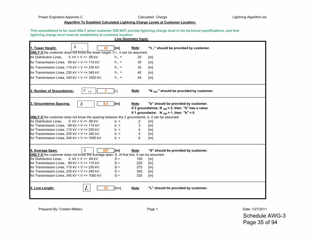
Power Engineers-Appendix C Calculated Charge Lightning Algorithm.xlsAlgorithm To Establish Calculated Lightning Charge Levels at Customer Location:
This spreadsheet to be used ONLY when customer DID NOT provide lightning charge level in his technical specifications, and thatlightning charge level must be established at customer location.
Line Geometry Input:
1. Tower Height: 42 [m] Note: "h t " should be provided by customer.ONLY if the customer does not know the tower height: h t , it can be assumed:for Distribution Lines, 0 kV < V <= 69 kV: h t = 25 [m]for Transmission Lines, 69 kV < V <= 115 kV: h t = 30 [m]for Transmission Lines, 115 kV < V <= 230 kV: h t = 35 [m]for Transmission Lines, 230 kV < V <= 345 kV: h t = 40 [m]for Transmission Lines, 345 kV < V <= 1000 kV: h t = 45 [m]
2. Number of Groundwires: 2 [-] Note: "N GW " should be provided by customer.
3. Groundwires Spacing: 8.8 [m] Note: "b" should be provided by customer.if 2 groundwires: N GW = 2, then "b" has a valueif 1 groundwire: N GW = 1, then "b" = 0
ONLY if the customer does not know the spacing between the 2 groundwires: b, it can be assumed:for Distribution Lines, 0 kV < V <= 69 kV: b = 2 [m]for Transmission Lines, 69 kV < V <= 115 kV: b = 3 [m]for Transmission Lines, 115 kV < V <= 230 kV: b = 4 [m]for Transmission Lines, 230 kV < V <= 345 kV: b = 5 [m]for Transmission Lines, 345 kV < V <= 1000 kV: b = 6 [m]
4. Average Span: 457 [m] Note: "S" should be provided by customer.ONLY if the customer does not know the average span: S, of that line, it can be assumed: for Distribution Lines, 0 kV < V <= 69 kV: S = 100 [m]for Transmission Lines, 69 kV < V <= 115 kV: S = 225 [m]for Transmission Lines, 115 kV < V <= 230 kV: S = 275 [m]for Transmission Lines, 230 kV < V <= 345 kV: S = 300 [m]for Transmission Lines, 345 kV < V <= 1000 kV: S = 325 [m]
5. Line Length: 30 [km] Note: "L" should be provided by customer.
th
b
S
GWN
L
Prepared By: Cristian Militaru Page 1 Date: 1/27/2011
Schedule AWG-3 Page 35 of 94
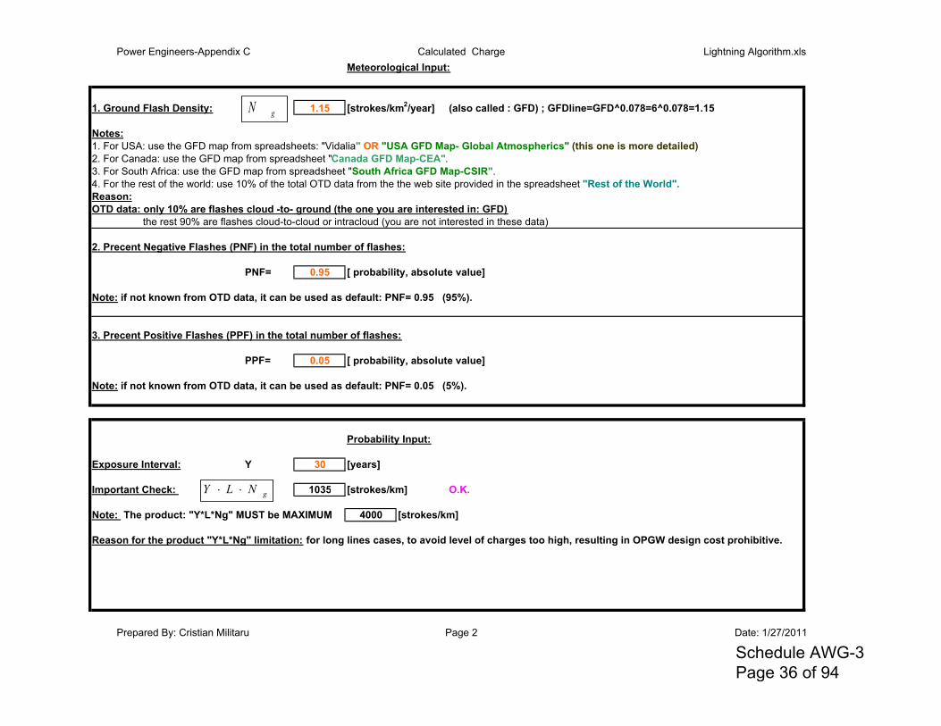
Power Engineers-Appendix C Calculated Charge Lightning Algorithm.xlsMeteorological Input:
1. Ground Flash Density: 1.15 [strokes/km2/year] (also called : GFD) ; GFDline=GFD^0.078=6^0.078=1.15
Notes:1. For USA: use the GFD map from spreadsheets: "Vidalia" OR "USA GFD Map- Global Atmospherics" (this one is more detailed)2. For Canada: use the GFD map from spreadsheet "Canada GFD Map-CEA".3. For South Africa: use the GFD map from spreadsheet "South Africa GFD Map-CSIR".4. For the rest of the world: use 10% of the total OTD data from the the web site provided in the spreadsheet "Rest of the World".Reason:OTD data: only 10% are flashes cloud -to- ground (the one you are interested in: GFD)
the rest 90% are flashes cloud-to-cloud or intracloud (you are not interested in these data)
2. Precent Negative Flashes (PNF) in the total number of flashes:
PNF= 0.95 [ probability, absolute value]
Note: if not known from OTD data, it can be used as default: PNF= 0.95 (95%).
3. Precent Positive Flashes (PPF) in the total number of flashes:
PPF= 0.05 [ probability, absolute value]
Note: if not known from OTD data, it can be used as default: PNF= 0.05 (5%).
Probability Input:
Exposure Interval: Y 30 [years]
Important Check: 1035 [strokes/km] O.K.
Note: The product: "Y*L*Ng" MUST be MAXIMUM 4000 [strokes/km]
Reason for the product "Y*L*Ng" limitation: for long lines cases, to avoid level of charges too high, resulting in OPGW design cost prohibitive.
gN
gNLY
Prepared By: Cristian Militaru Page 2 Date: 1/27/2011
Schedule AWG-3 Page 36 of 94
Power Engineers-Appendix C Calculated Charge Lightning Algorithm.xls
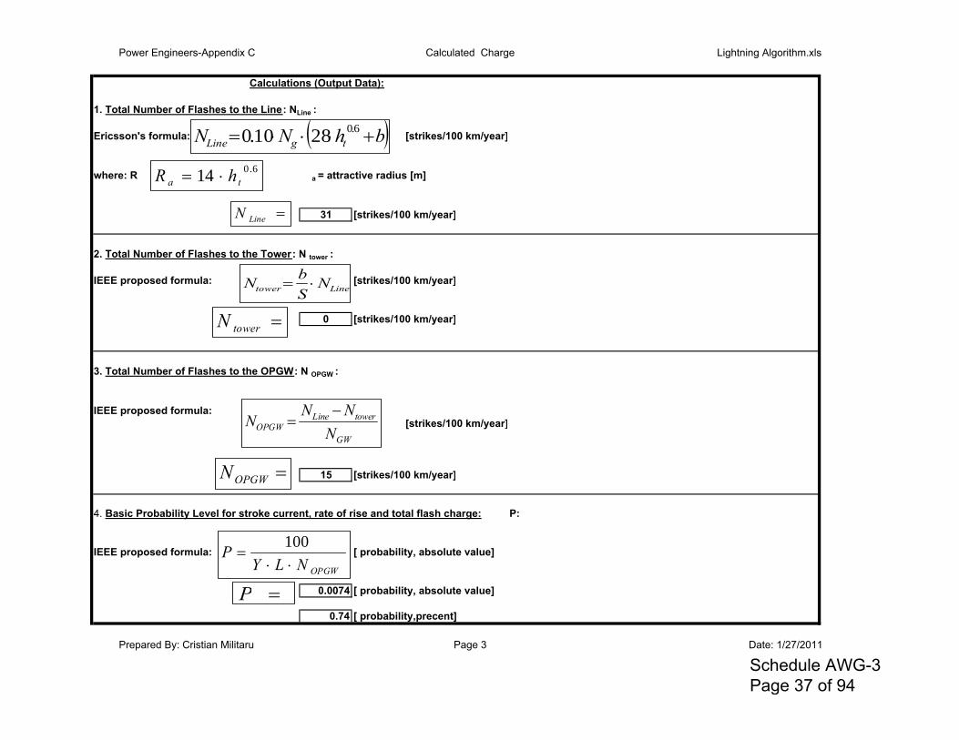
Calculations (Output Data):
1. Total Number of Flashes to the Line: NLine :
Ericsson's formula: [strikes/100 km/year]
where: R a = attractive radius [m]
31 [strikes/100 km/year]
2. Total Number of Flashes to the Tower: N tower :
IEEE proposed formula: [strikes/100 km/year]
0 [strikes/100 km/year]
3. Total Number of Flashes to the OPGW: N OPGW :
IEEE proposed formula:[strikes/100 km/year]
15 [strikes/100 km/year]
4. Basic Probability Level for stroke current, rate of rise and total flash charge: P:
IEEE proposed formula: [ probability, absolute value]
0.0074 [ probability, absolute value]
0.74 [ probability,precent]
bhNN tgLine 6.02810.06.014 ta hR
LineN
Linetower NSbN
towerN
GW
towerLineOPGW N
NNN
OPGWN
OPGWNLYP
100
P
Prepared By: Cristian Militaru Page 3 Date: 1/27/2011
Schedule AWG-3 Page 37 of 94
Power Engineers-Appendix C Calculated Charge Lightning Algorithm.xls
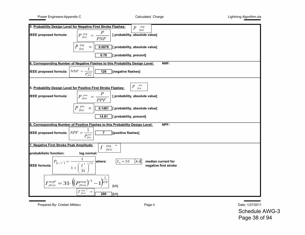
5. Probability Design Level for Negative First Stroke Flashes:
IEEE proposed formula: [ probability, absolute value]
0.0078 [ probability, absolute value]
0.78 [ probability, precent]
6. Corresponding Number of Negative Flashes to this Probability Design Level: NNF:
IEEE proposed formula: 128 [negative flashes]
5. Probability Design Level for Positive First Stroke Flashes:
IEEE proposed formula: [ probability, absolute value]
0.1481 [ probability, absolute value]
14.81 [ probability, precent]
6. Corresponding Number of Positive Flashes to this Probability Design Level: NPF:
IEEE proposed formula: 7 [positive flashes]
7. Negative First Stroke Peak Amplitude:
probabilistic function: log normal:
where: median current for IEEE formula: negative first stroke
[kA]
200 [kA]
PNFPP neg
first
negfirstP
negfirstP
NNF 1
PPFPP pos
first
posfirstP
posfirstP
NPF 1
negfirstP
posfirstP
*negfirstI
6.2*
311
1*
IP II
kAIm 31
6.21
1* 131 neg
firstnegfirst PI
*negfirstI
Prepared By: Cristian Militaru Page 4 Date: 1/27/2011
Schedule AWG-3 Page 38 of 94
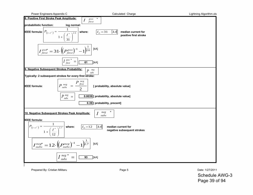
Power Engineers-Appendix C Calculated Charge Lightning Algorithm.xls8. Positive First Stroke Peak Amplitude:
probabilistic function: log normal:
IEEE formula: where: median current for positive first stroke
[kA]
61 [kA]
9. Negative Subsequent Strokes Probability:
Typically: 2 subsequent strokes for every first stroke:
IEEE formula: [ probability, absolute value]
0.0039 [ probability, absolute value]
0.39 [ probability, precent]
10. Negative Subsequent Strokes Peak Amplitude:
IEEE formula:
where: median current for negative subsequent strokes
[kA]
93 [kA]
*posfirstI
6.2*
311
1*
IP II kAIm 31
6.21
1* 131 pos
firstposfirst PI
*posfirstI
2
negfirstneg
subs
PP
negsubsP
7.2*
121
1*
IP II kAIm 12
7.21
1* 112 neg
subsnegsubs PI
*negsubsI
*negsubsI
negsubsP
Prepared By: Cristian Militaru Page 5 Date: 1/27/2011
Schedule AWG-3 Page 39 of 94
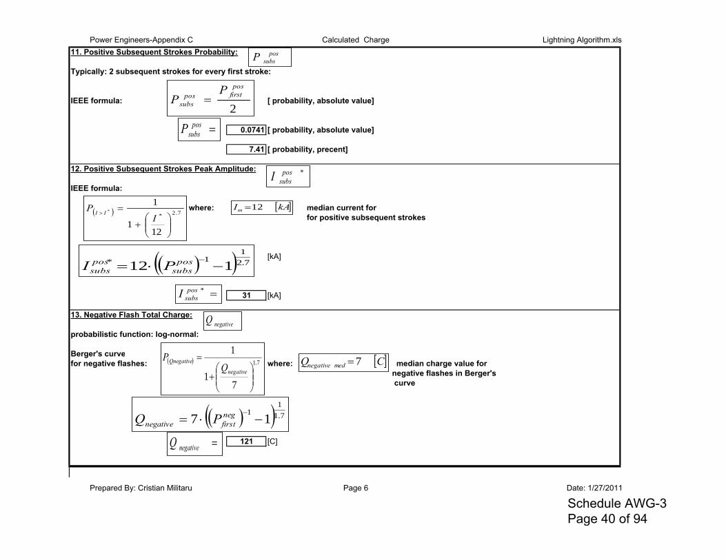
Power Engineers-Appendix C Calculated Charge Lightning Algorithm.xls11. Positive Subsequent Strokes Probability:
Typically: 2 subsequent strokes for every first stroke:
IEEE formula: [ probability, absolute value]
0.0741 [ probability, absolute value]
7.41 [ probability, precent]
12. Positive Subsequent Strokes Peak Amplitude:
IEEE formula:
where: median current forfor positive subsequent strokes
[kA]
31 [kA]
13. Negative Flash Total Charge:
probabilistic function: log-normal:
Berger's curvefor negative flashes: where: median charge value for
negative flashes in Berger's curve
[C]
121 [C]
2
posfirstpos
subs
PP
possubsP
7.2*
121
1*
IP II
kAIm 12
7.21
1* 112 pos
subspossubs PI
*possubsI
7.1
71
1
negative
QnegativeQ
P CQ mednegative 7
7.11
1 17 neg
firstnegative PQ
negativeQ
*possubsI
possubsP
negativeQ
Prepared By: Cristian Militaru Page 6 Date: 1/27/2011
Schedule AWG-3 Page 40 of 94
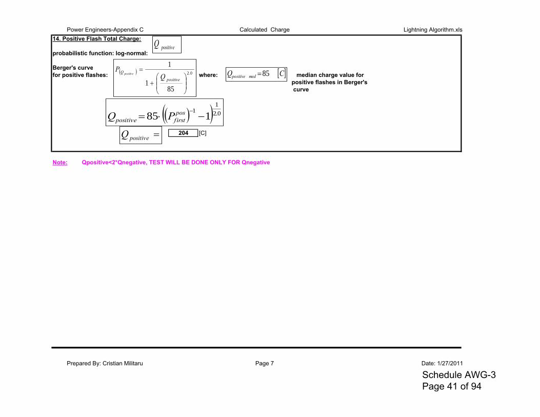
Power Engineers-Appendix C Calculated Charge Lightning Algorithm.xls14. Positive Flash Total Charge:
probabilistic function: log-normal:
Berger's curvefor positive flashes: where: median charge value for
positive flashes in Berger's curve
[C]
204 [C]
Note: Qpositive<2*Qnegative, TEST WILL BE DONE ONLY FOR Qnegative
0.2
851
1
positive
Ppositive CQ medpositive 85
0.21
1 185 pos
firstpositive PQ
positiveQ
positiveQ
Prepared By: Cristian Militaru Page 7 Date: 1/27/2011
Schedule AWG-3 Page 41 of 94
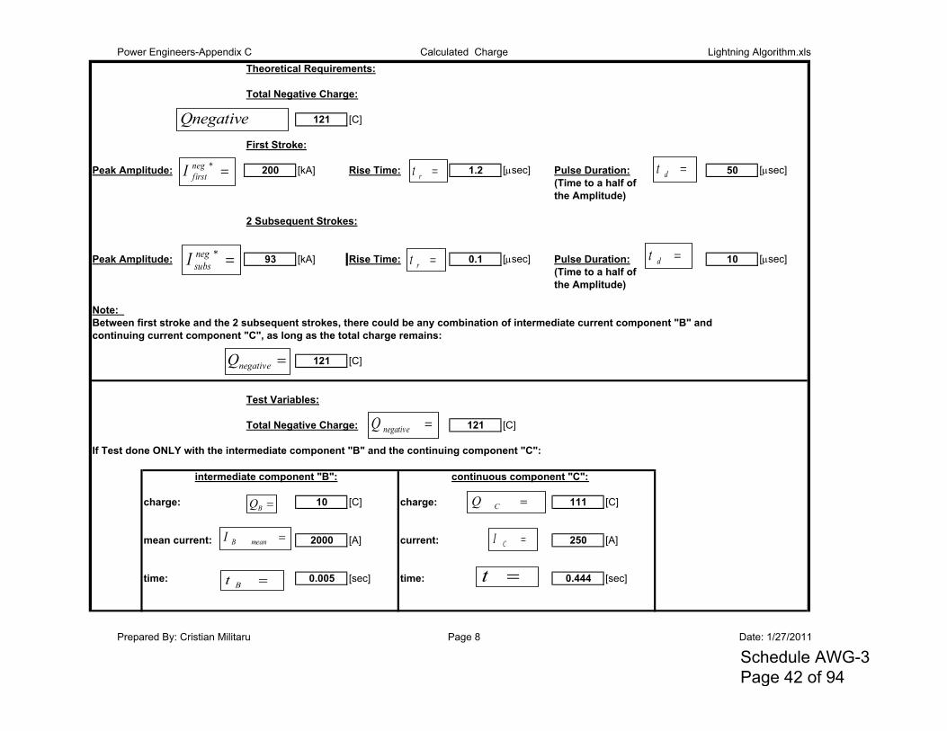
Power Engineers-Appendix C Calculated Charge Lightning Algorithm.xlsTheoretical Requirements:
Total Negative Charge:
121 [C]
First Stroke:
Peak Amplitude: 200 [kA] Rise Time: 1.2 [sec] Pulse Duration: 50 [sec](Time to a half of the Amplitude)
2 Subsequent Strokes:
Peak Amplitude: 93 [kA] Rise Time: 0.1 [sec] Pulse Duration: 10 [sec](Time to a half of the Amplitude)
Note: Between first stroke and the 2 subsequent strokes, there could be any combination of intermediate current component "B" and continuing current component "C", as long as the total charge remains:
121 [C]
Test Variables:
Total Negative Charge: 121 [C]
If Test done ONLY with the intermediate component "B" and the continuing component "C":
intermediate component "B": continuous component "C":
charge: 10 [C] charge: 111 [C]
mean current: 2000 [A] current: 250 [A]
time: 0.005 [sec] time: 0.444 [sec]
Qnegative
*negfirstI rt dt
*negsubsI rt dt
negativeQ
negativeQ
meanBI
t
BQ
Bt
CQ
CI
Prepared By: Cristian Militaru Page 8 Date: 1/27/2011
Schedule AWG-3 Page 42 of 94
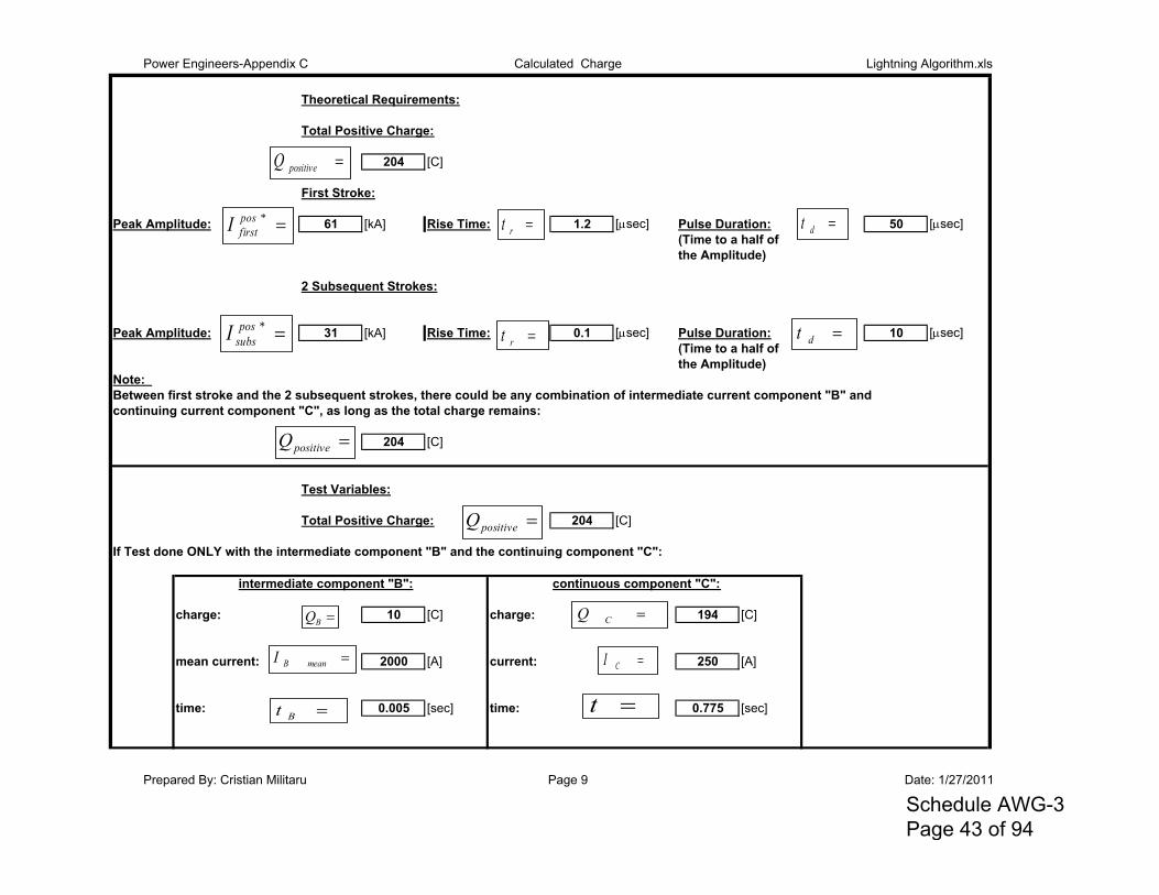
Power Engineers-Appendix C Calculated Charge Lightning Algorithm.xls
Theoretical Requirements:
Total Positive Charge:
204 [C]
First Stroke:
Peak Amplitude: 61 [kA] Rise Time: 1.2 [sec] Pulse Duration: 50 [sec](Time to a half of the Amplitude)
2 Subsequent Strokes:
Peak Amplitude: 31 [kA] Rise Time: 0.1 [sec] Pulse Duration: 10 [sec](Time to a half of the Amplitude)
Note: Between first stroke and the 2 subsequent strokes, there could be any combination of intermediate current component "B" andcontinuing current component "C", as long as the total charge remains:
204 [C]
Test Variables:
Total Positive Charge: 204 [C]
If Test done ONLY with the intermediate component "B" and the continuing component "C":
intermediate component "B": continuous component "C":
charge: 10 [C] charge: 194 [C]
mean current: 2000 [A] current: 250 [A]
time: 0.005 [sec] time: 0.775 [sec]
positiveQ
*posfirstI rt dt
*possubsI rt dt
positiveQ
positiveQ
meanBI
t
BQ
Bt
CQ
CI
Prepared By: Cristian Militaru Page 9 Date: 1/27/2011
Schedule AWG-3 Page 43 of 94
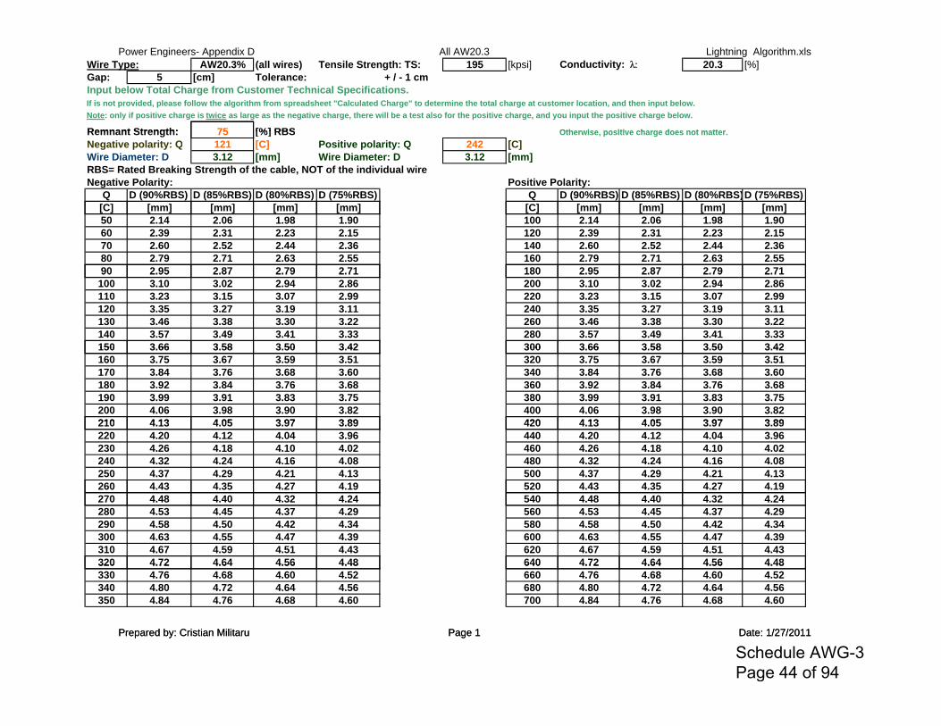
Power Engineers- Appendix D All AW20.3 Lightning Algorithm.xlsWire Type: AW20.3% (all wires) Tensile Strength: TS: 195 [kpsi] Conductivity: 20.3 [%]Gap: 5 [cm] Tolerance: + / - 1 cmInput below Total Charge from Customer Technical Specifications.If is not provided, please follow the algorithm from spreadsheet "Calculated Charge" to determine the total charge at customer location, and then input below.Note: only if positive charge is twice as large as the negative charge, there will be a test also for the positive charge, and you input the positive charge below.
Remnant Strength: 75 [%] RBS Otherwise positive charge does not matter
Prepared by: Cristian Militaru Page 1 Date: 1/27/2011
Remnant Strength: 75 [%] RBS Otherwise, positive charge does not matter.Negative polarity: Q 121 [C] Positive polarity: Q 242 [C]Wire Diameter: D 3.12 [mm] Wire Diameter: D 3.12 [mm]RBS= Rated Breaking Strength of the cable, NOT of the individual wireNegative Polarity: Positive Polarity:
Q D (90%RBS) D (85%RBS) D (80%RBS) D (75%RBS) Q D (90%RBS) D (85%RBS) D (80%RBS)D (75%RBS)[C] [ ] [ ] [ ] [ ] [C] [ ] [ ] [ ] [ ][C] [mm] [mm] [mm] [mm] [C] [mm] [mm] [mm] [mm]50 2.14 2.06 1.98 1.90 100 2.14 2.06 1.98 1.9060 2.39 2.31 2.23 2.15 120 2.39 2.31 2.23 2.1570 2.60 2.52 2.44 2.36 140 2.60 2.52 2.44 2.3680 2.79 2.71 2.63 2.55 160 2.79 2.71 2.63 2.5590 2.95 2.87 2.79 2.71 180 2.95 2.87 2.79 2.7190 2.95 2.87 2.79 2.71 180 2.95 2.87 2.79 2.71100 3.10 3.02 2.94 2.86 200 3.10 3.02 2.94 2.86110 3.23 3.15 3.07 2.99 220 3.23 3.15 3.07 2.99120 3.35 3.27 3.19 3.11 240 3.35 3.27 3.19 3.11130 3.46 3.38 3.30 3.22 260 3.46 3.38 3.30 3.22140 3.57 3.49 3.41 3.33 280 3.57 3.49 3.41 3.33150 3 66 3 58 3 50 3 42 300 3 66 3 58 3 50 3 42150 3.66 3.58 3.50 3.42 300 3.66 3.58 3.50 3.42160 3.75 3.67 3.59 3.51 320 3.75 3.67 3.59 3.51170 3.84 3.76 3.68 3.60 340 3.84 3.76 3.68 3.60180 3.92 3.84 3.76 3.68 360 3.92 3.84 3.76 3.68190 3.99 3.91 3.83 3.75 380 3.99 3.91 3.83 3.75200 4.06 3.98 3.90 3.82 400 4.06 3.98 3.90 3.82210 4 13 4 05 3 97 3 89 420 4 13 4 05 3 97 3 89210 4.13 4.05 3.97 3.89 420 4.13 4.05 3.97 3.89220 4.20 4.12 4.04 3.96 440 4.20 4.12 4.04 3.96230 4.26 4.18 4.10 4.02 460 4.26 4.18 4.10 4.02240 4.32 4.24 4.16 4.08 480 4.32 4.24 4.16 4.08250 4.37 4.29 4.21 4.13 500 4.37 4.29 4.21 4.13260 4.43 4.35 4.27 4.19 520 4.43 4.35 4.27 4.19270 4.48 4.40 4.32 4.24 540 4.48 4.40 4.32 4.24280 4.53 4.45 4.37 4.29 560 4.53 4.45 4.37 4.29290 4.58 4.50 4.42 4.34 580 4.58 4.50 4.42 4.34300 4.63 4.55 4.47 4.39 600 4.63 4.55 4.47 4.39310 4.67 4.59 4.51 4.43 620 4.67 4.59 4.51 4.43320 4.72 4.64 4.56 4.48 640 4.72 4.64 4.56 4.48320 4.72 4.64 4.56 4.48 640 4.72 4.64 4.56 4.48330 4.76 4.68 4.60 4.52 660 4.76 4.68 4.60 4.52340 4.80 4.72 4.64 4.56 680 4.80 4.72 4.64 4.56350 4.84 4.76 4.68 4.60 700 4.84 4.76 4.68 4.60
Prepared by: Cristian Militaru Page 1 Date: 1/27/2011
Schedule AWG-3 Page 44 of 94
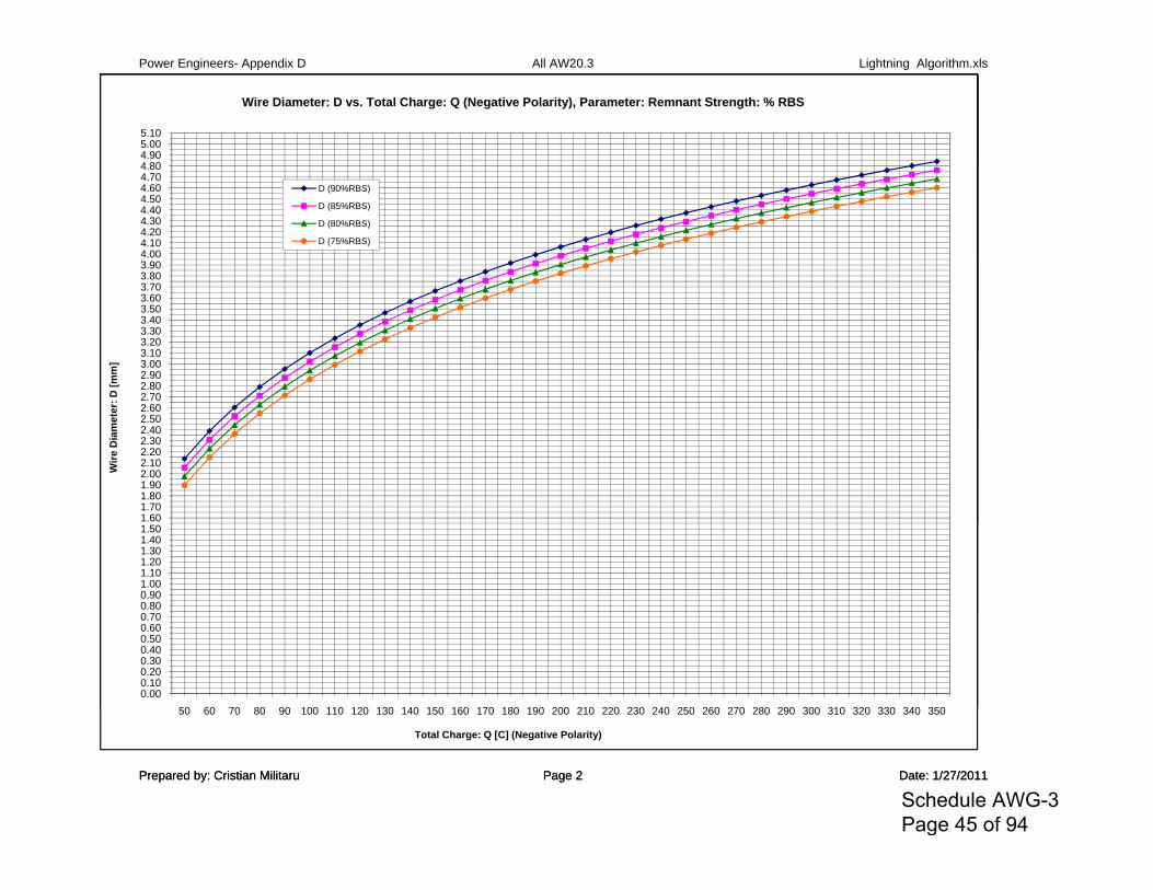
Power Engineers- Appendix D All AW20.3 Lightning Algorithm.xls
4 804.905.005.10
Wire Diameter: D vs. Total Charge: Q (Negative Polarity), Parameter: Remnant Strength: % RBS
Prepared by: Cristian Militaru Page 2 Date: 1/27/2011
4.004.104.204.304.404.504.604.704.804.905.005.10
Wire Diameter: D vs. Total Charge: Q (Negative Polarity), Parameter: Remnant Strength: % RBS
D (90%RBS)
D (85%RBS)
D (80%RBS)
D (75%RBS)
3 103.203.303.403.503.603.703.803.904.004.104.204.304.404.504.604.704.804.905.005.10
Wire Diameter: D vs. Total Charge: Q (Negative Polarity), Parameter: Remnant Strength: % RBS
D (90%RBS)
D (85%RBS)
D (80%RBS)
D (75%RBS)
2 402.502.602.702.802.903.003.103.203.303.403.503.603.703.803.904.004.104.204.304.404.504.604.704.804.905.005.10
met
er: D
[mm
]Wire Diameter: D vs. Total Charge: Q (Negative Polarity), Parameter: Remnant Strength: % RBS
D (90%RBS)
D (85%RBS)
D (80%RBS)
D (75%RBS)
1.601.701.801.902.002.102.202.302.402.502.602.702.802.903.003.103.203.303.403.503.603.703.803.904.004.104.204.304.404.504.604.704.804.905.005.10
Wire
Dia
met
er: D
[mm
]Wire Diameter: D vs. Total Charge: Q (Negative Polarity), Parameter: Remnant Strength: % RBS
D (90%RBS)
D (85%RBS)
D (80%RBS)
D (75%RBS)
0 700.800.901.001.101.201.301.401.501.601.701.801.902.002.102.202.302.402.502.602.702.802.903.003.103.203.303.403.503.603.703.803.904.004.104.204.304.404.504.604.704.804.905.005.10
Wire
Dia
met
er: D
[mm
]Wire Diameter: D vs. Total Charge: Q (Negative Polarity), Parameter: Remnant Strength: % RBS
D (90%RBS)
D (85%RBS)
D (80%RBS)
D (75%RBS)
0.000.100.200.300.400.500.600.700.800.901.001.101.201.301.401.501.601.701.801.902.002.102.202.302.402.502.602.702.802.903.003.103.203.303.403.503.603.703.803.904.004.104.204.304.404.504.604.704.804.905.005.10
50 60 70 80 90 100 110 120 130 140 150 160 170 180 190 200 210 220 230 240 250 260 270 280 290 300 310 320 330 340 350
Wire
Dia
met
er: D
[mm
]
Total Charge: Q [C] (Negative Polarity)
Wire Diameter: D vs. Total Charge: Q (Negative Polarity), Parameter: Remnant Strength: % RBS
D (90%RBS)
D (85%RBS)
D (80%RBS)
D (75%RBS)
Prepared by: Cristian Militaru Page 2 Date: 1/27/2011
Schedule AWG-3 Page 45 of 94
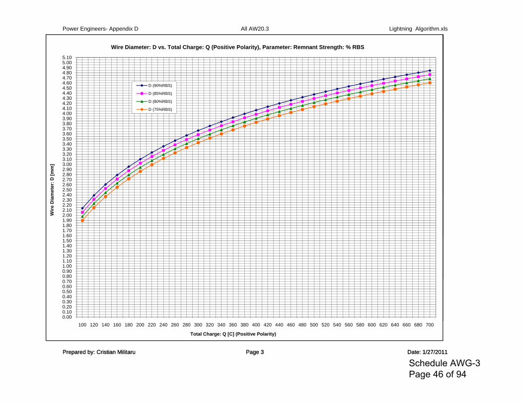
Power Engineers- Appendix D All AW20.3 Lightning Algorithm.xls
4.804.905.005.10
Wire Diameter: D vs. Total Charge: Q (Positive Polarity), Parameter: Remnant Strength: % RBS
Prepared by: Cristian Militaru Page 3 Date: 1/27/2011
3 904.004.104.204.304.404.504.604.704.804.905.005.10
Wire Diameter: D vs. Total Charge: Q (Positive Polarity), Parameter: Remnant Strength: % RBS
D (90%RBS)
D (85%RBS)
D (80%RBS)
D (75%RBS)
3 103.203.303.403.503.603.703.803.904.004.104.204.304.404.504.604.704.804.905.005.10
Wire Diameter: D vs. Total Charge: Q (Positive Polarity), Parameter: Remnant Strength: % RBS
D (90%RBS)
D (85%RBS)
D (80%RBS)
D (75%RBS)
2 402.502.602.702.802.903.003.103.203.303.403.503.603.703.803.904.004.104.204.304.404.504.604.704.804.905.005.10
met
er: D
[mm
]Wire Diameter: D vs. Total Charge: Q (Positive Polarity), Parameter: Remnant Strength: % RBS
D (90%RBS)
D (85%RBS)
D (80%RBS)
D (75%RBS)
1 601.701.801.902.002.102.202.302.402.502.602.702.802.903.003.103.203.303.403.503.603.703.803.904.004.104.204.304.404.504.604.704.804.905.005.10
Wire
Dia
met
er: D
[mm
]Wire Diameter: D vs. Total Charge: Q (Positive Polarity), Parameter: Remnant Strength: % RBS
D (90%RBS)
D (85%RBS)
D (80%RBS)
D (75%RBS)
0.800.901.001.101.201.301.401.501.601.701.801.902.002.102.202.302.402.502.602.702.802.903.003.103.203.303.403.503.603.703.803.904.004.104.204.304.404.504.604.704.804.905.005.10
Wire
Dia
met
er: D
[mm
]Wire Diameter: D vs. Total Charge: Q (Positive Polarity), Parameter: Remnant Strength: % RBS
D (90%RBS)
D (85%RBS)
D (80%RBS)
D (75%RBS)
0.000.100.200.300.400.500.600.700.800.901.001.101.201.301.401.501.601.701.801.902.002.102.202.302.402.502.602.702.802.903.003.103.203.303.403.503.603.703.803.904.004.104.204.304.404.504.604.704.804.905.005.10
100 120 140 160 180 200 220 240 260 280 300 320 340 360 380 400 420 440 460 480 500 520 540 560 580 600 620 640 660 680 700
Wire
Dia
met
er: D
[mm
]
Total Charge: Q [C] (Positive Polarity)
Wire Diameter: D vs. Total Charge: Q (Positive Polarity), Parameter: Remnant Strength: % RBS
D (90%RBS)
D (85%RBS)
D (80%RBS)
D (75%RBS)
Prepared by: Cristian Militaru Page 3 Date: 1/27/2011
Schedule AWG-3 Page 46 of 94
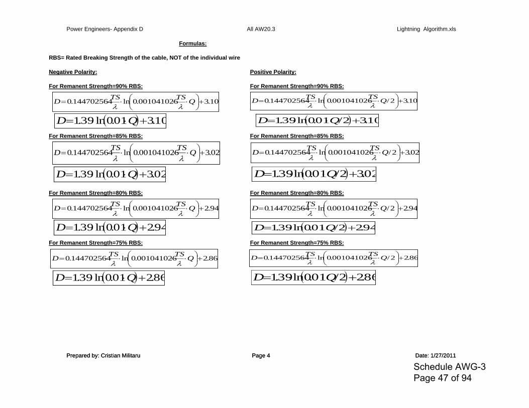
Power Engineers- Appendix D All AW20.3 Lightning Algorithm.xls
Formulas:
RBS= Rated Breaking Strength of the cable, NOT of the individual wire
Negative Polarity: Positive Polarity:
10.3001041026.0ln144702564.0
QTSTSD
10.301.0ln39.1 QD
02.3001041026.0ln144702564.0
QTSTSD
02.301.0ln39.1 QD
10.32/001041026.0ln144702564.0
QTSTSD
10.32/01.0ln39.1 QD
02.32/001041026.0ln144702564.0
QTSTSD
02.32/01.0ln39.1 QD
94.2001041026.0ln144702564.0
QTSTSD
94.201.0ln39.1 QD
86.2001041026.0ln144702564.0
QTSTSD
86.201.0ln39.1 QD
94.22/001041026.0ln144702564.0
QTSTSD
94.22/01.0ln39.1 QD
86.22/001041026.0ln144702564.0
QTSTSD
86.22/01.0ln39.1 QD
Prepared by: Cristian Militaru Page 4 Date: 1/27/2011
Negative Polarity: Positive Polarity:
For Remanent Strength=90% RBS: For Remanent Strength=90% RBS:
10.3001041026.0ln144702564.0
QTSTSD
10.301.0ln39.1 QD
02.3001041026.0ln144702564.0
QTSTSD
02.301.0ln39.1 QD
10.32/001041026.0ln144702564.0
QTSTSD
10.32/01.0ln39.1 QD
02.32/001041026.0ln144702564.0
QTSTSD
02.32/01.0ln39.1 QD
94.2001041026.0ln144702564.0
QTSTSD
94.201.0ln39.1 QD
86.2001041026.0ln144702564.0
QTSTSD
86.201.0ln39.1 QD
94.22/001041026.0ln144702564.0
QTSTSD
94.22/01.0ln39.1 QD
86.22/001041026.0ln144702564.0
QTSTSD
86.22/01.0ln39.1 QD
For Remanent Strength=85% RBS: For Remanent Strength=85% RBS:
10.3001041026.0ln144702564.0
QTSTSD
10.301.0ln39.1 QD
02.3001041026.0ln144702564.0
QTSTSD
02.301.0ln39.1 QD
10.32/001041026.0ln144702564.0
QTSTSD
10.32/01.0ln39.1 QD
02.32/001041026.0ln144702564.0
QTSTSD
02.32/01.0ln39.1 QD
94.2001041026.0ln144702564.0
QTSTSD
94.201.0ln39.1 QD
86.2001041026.0ln144702564.0
QTSTSD
86.201.0ln39.1 QD
94.22/001041026.0ln144702564.0
QTSTSD
94.22/01.0ln39.1 QD
86.22/001041026.0ln144702564.0
QTSTSD
86.22/01.0ln39.1 QD
For Remanent Strength=80% RBS: For Remanent Strength=80% RBS:
10.3001041026.0ln144702564.0
QTSTSD
10.301.0ln39.1 QD
02.3001041026.0ln144702564.0
QTSTSD
02.301.0ln39.1 QD
10.32/001041026.0ln144702564.0
QTSTSD
10.32/01.0ln39.1 QD
02.32/001041026.0ln144702564.0
QTSTSD
02.32/01.0ln39.1 QD
94.2001041026.0ln144702564.0
QTSTSD
94.201.0ln39.1 QD
86.2001041026.0ln144702564.0
QTSTSD
86.201.0ln39.1 QD
94.22/001041026.0ln144702564.0
QTSTSD
94.22/01.0ln39.1 QD
86.22/001041026.0ln144702564.0
QTSTSD
86.22/01.0ln39.1 QD
g % g %
10.3001041026.0ln144702564.0
QTSTSD
10.301.0ln39.1 QD
02.3001041026.0ln144702564.0
QTSTSD
02.301.0ln39.1 QD
10.32/001041026.0ln144702564.0
QTSTSD
10.32/01.0ln39.1 QD
02.32/001041026.0ln144702564.0
QTSTSD
02.32/01.0ln39.1 QD
94.2001041026.0ln144702564.0
QTSTSD
94.201.0ln39.1 QD
86.2001041026.0ln144702564.0
QTSTSD
86.201.0ln39.1 QD
94.22/001041026.0ln144702564.0
QTSTSD
94.22/01.0ln39.1 QD
86.22/001041026.0ln144702564.0
QTSTSD
86.22/01.0ln39.1 QD
For Remanent Strength=75% RBS: For Remanent Strength=75% RBS:
10.3001041026.0ln144702564.0
QTSTSD
10.301.0ln39.1 QD
02.3001041026.0ln144702564.0
QTSTSD
02.301.0ln39.1 QD
10.32/001041026.0ln144702564.0
QTSTSD
10.32/01.0ln39.1 QD
02.32/001041026.0ln144702564.0
QTSTSD
02.32/01.0ln39.1 QD
94.2001041026.0ln144702564.0
QTSTSD
94.201.0ln39.1 QD
86.2001041026.0ln144702564.0
QTSTSD
86.201.0ln39.1 QD
94.22/001041026.0ln144702564.0
QTSTSD
94.22/01.0ln39.1 QD
86.22/001041026.0ln144702564.0
QTSTSD
86.22/01.0ln39.1 QD
Prepared by: Cristian Militaru Page 4 Date: 1/27/2011
Schedule AWG-3 Page 47 of 94
Power Engineers- Appendix D All AW20.3 Lightning Algorithm.xls
41 902 853 804 75
Prepared by: Cristian Militaru Page 5 Date: 1/27/2011
4 75
Prepared by: Cristian Militaru Page 5 Date: 1/27/2011
Schedule AWG-3 Page 48 of 94
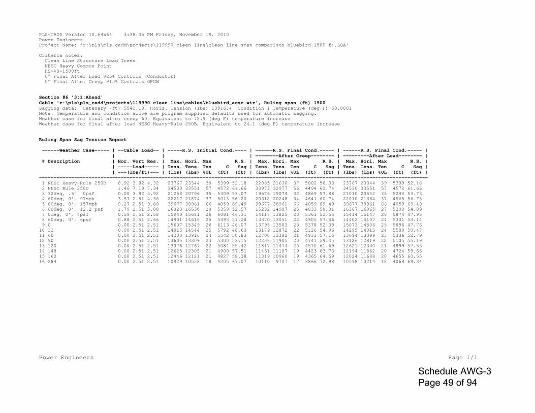
Power Engineers Page 1/1
PLS-CADD Version 10.64x64 3:38:35 PM Friday, November 19, 2010Power EngineersProject Name: 'r:\pls\pls_cadd\projects\119990 clean line\clean line_span comparison_bluebird_1500 ft.LOA'
Criteria notes: Clean Line Structure Load Trees NESC Heavy Common Point HS=VS=1500ft 0° Final After Load @25% Controls (Conductor) 0° Final After Creep @15% Controls OPGW
Section #6 '3:1:Ahead'Cable 'r:\pls\pls_cadd\projects\119990 clean line\cables\bluebird_acsr.wir', Ruling span (ft) 1500Sagging data: Catenary (ft) 5542.19, Horiz. Tension (lbs) 13916.4 Condition I Temperature (deg F) 60.0001Note: Temperature and condition above are program supplied defaults used for automatic sagging.Weather case for final after creep 60, Equivalent to 78.9 (deg F) temperature increaseWeather case for final after load NESC Heavy-Rule 250B, Equivalent to 24.1 (deg F) temperature increase
Ruling Span Sag Tension Report
------Weather Case----- | --Cable Load-- | -----R.S. Initial Cond.---- | ------R.S. Final Cond.----- | ------R.S. Final Cond.----- | | | | --------After Creep-------- | ---------After Load-------- | # Description | Hor. Vert Res. | Max. Hori. Max R.S. | Max. Hori. Max R.S. | Max. Hori. Max R.S. | | -----Load----- | Tens. Tens. Ten C Sag | Tens. Tens. Ten C Sag | Tens. Tens. Ten C Sag | | ---(lbs/ft)--- | (lbs) (lbs) %UL (ft) (ft) | (lbs) (lbs) %UL (ft) (ft) | (lbs) (lbs) %UL (ft) (ft) |------------------------------------------------------------------------------------------------------------------------------------- 1 NESC Heavy-Rule 250B 0.92 3.92 4.32 23767 23344 39 5399 52.18 22085 21630 37 5002 56.33 23767 23344 39 5399 52.18 2 NESC Rule 250D 1.46 7.19 7.34 34530 33551 57 4572 61.66 33973 32977 56 4494 62.74 34530 33551 57 4572 61.66 3 32deg, .5", 0psf 0.00 3.92 3.92 21258 20796 35 5309 53.07 19576 19074 32 4869 57.88 21010 20542 35 5244 53.73 4 60deg, 0", 97mph 3.57 2.51 4.36 22217 21874 37 5013 56.20 20618 20248 34 4641 60.74 22010 21664 37 4965 56.75 5 60deg, 0", 157mph 9.27 2.51 9.60 39677 38961 66 4059 69.49 39677 38961 66 4059 69.49 39677 38961 66 4059 69.49 6 60deg, 0", 12.2 psf 1.79 2.51 3.08 16823 16530 28 5359 52.57 15232 14907 25 4833 58.31 16367 16065 27 5208 54.09 7 0deg, 0", 4psf 0.59 2.51 2.58 15940 15681 26 6081 46.31 14117 13825 23 5361 52.55 15414 15147 26 5874 47.95 8 60deg, 0", 6psf 0.88 2.51 2.66 14901 14616 25 5493 51.28 13370 13051 22 4905 57.46 14402 14107 24 5301 53.14 9 0 0.00 2.51 2.51 15607 15349 26 6113 46.07 13795 13503 23 5378 52.39 15073 14806 25 5896 47.76 10 32 0.00 2.51 2.51 14815 14544 25 5792 48.63 13179 12872 22 5126 54.96 14295 14013 24 5580 50.47 11 60 0.00 2.51 2.51 14200 13916 24 5542 50.83 12700 12382 21 4931 57.15 13694 13399 23 5336 52.79 12 90 0.00 2.51 2.51 13605 13309 23 5300 53.15 12236 11905 20 4741 59.45 13126 12819 22 5105 55.19 13 120 0.00 2.51 2.51 13076 12767 22 5084 55.42 11817 11474 20 4570 61.69 12621 12300 21 4899 57.53 14 148 0.00 2.51 2.51 12625 12305 21 4900 57.51 11461 11107 19 4423 63.73 12194 11862 20 4724 59.66 15 160 0.00 2.51 2.51 12446 12121 21 4827 58.38 11319 10960 19 4365 64.59 12024 11688 20 4655 60.55 16 284 0.00 2.51 2.51 10929 10558 18 4205 67.07 10110 9707 17 3866 72.98 10598 10214 18 4068 69.34
Schedule AWG-3 Page 49 of 94
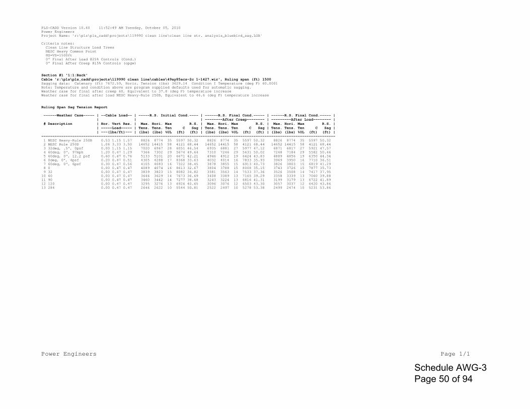
Power Engineers Page 1/1
PLS-CADD Version 10.60 11:52:49 AM Tuesday, October 05, 2010Power EngineersProject Name: 'r:\pls\pls_cadd\projects\119990 clean line\clean line str. analysis_bluebird_sag.LOA'
Criteria notes: Clean Line Structure Load Trees NESC Heavy Common Point HS=VS=1500ft 0° Final After Load @25% Controls (Cond.) 0° Final After Creep @15% Controls (opgw)
Section #1 '1:1:Back'Cable 'r:\pls\pls_cadd\projects\119990 clean line\cables\49ay85acs-2c 1-1427.wir', Ruling span (ft) 1500Sagging data: Catenary (ft) 7672.59, Horiz. Tension (lbs) 3629.14 Condition I Temperature (deg F) 60.0001Note: Temperature and condition above are program supplied defaults used for automatic sagging.Weather case for final after creep 60, Equivalent to 37.8 (deg F) temperature increaseWeather case for final after load NESC Heavy-Rule 250B, Equivalent to 46.6 (deg F) temperature increase
Ruling Span Sag Tension Report
------Weather Case----- | --Cable Load-- | -----R.S. Initial Cond.---- | ------R.S. Final Cond.----- | ------R.S. Final Cond.----- | | | | --------After Creep-------- | ---------After Load-------- | # Description | Hor. Vert Res. | Max. Hori. Max R.S. | Max. Hori. Max R.S. | Max. Hori. Max R.S. | | -----Load----- | Tens. Tens. Ten C Sag | Tens. Tens. Ten C Sag | Tens. Tens. Ten C Sag | | ---(lbs/ft)--- | (lbs) (lbs) %UL (ft) (ft) | (lbs) (lbs) %UL (ft) (ft) | (lbs) (lbs) %UL (ft) (ft) |------------------------------------------------------------------------------------------------------------------------------------- 1 NESC Heavy-Rule 250B 0.53 1.15 1.57 8826 8774 35 5597 50.32 8826 8774 35 5597 50.32 8826 8774 35 5597 50.32 2 NESC Rule 250D 1.06 3.33 3.50 14652 14415 58 4121 68.44 14652 14415 58 4121 68.44 14652 14415 58 4121 68.44 3 32deg, .5", 0psf 0.00 1.15 1.15 7020 6967 28 6051 46.54 6935 6881 27 5977 47.12 6871 6817 27 5921 47.57 4 60deg, 0", 97mph 1.20 0.47 1.29 7366 7302 29 5674 49.64 7310 7246 29 5631 50.02 7248 7184 29 5582 50.46 5 60deg, 0", 12.2 psf 0.60 0.47 0.76 5133 5101 20 6671 42.21 4946 4912 19 6424 43.83 4889 4856 19 6350 44.34 6 0deg, 0", 4psf 0.20 0.47 0.51 4305 4288 17 8368 33.63 4032 4014 16 7833 35.93 3969 3950 16 7710 36.51 7 60deg, 0", 6psf 0.30 0.47 0.56 4105 4083 16 7322 38.45 3878 3855 15 6913 40.73 3826 3803 15 6819 41.29 8 0 0.00 0.47 0.47 4089 4074 16 8613 32.67 3804 3788 15 8008 35.15 3743 3726 15 7877 35.73 9 32 0.00 0.47 0.47 3839 3823 15 8082 34.82 3581 3563 14 7533 37.36 3526 3508 14 7417 37.95 10 60 0.00 0.47 0.47 3646 3629 14 7673 36.69 3408 3389 13 7165 39.29 3358 3339 13 7060 39.88 11 90 0.00 0.47 0.47 3460 3442 14 7277 38.68 3243 3224 13 6816 41.31 3199 3179 13 6722 41.89 12 120 0.00 0.47 0.47 3295 3276 13 6926 40.65 3096 3076 12 6503 43.30 3057 3037 12 6420 43.86 13 284 0.00 0.47 0.47 2646 2622 10 5544 50.81 2522 2497 10 5278 53.38 2499 2474 10 5231 53.86
Schedule AWG-3 Page 50 of 94
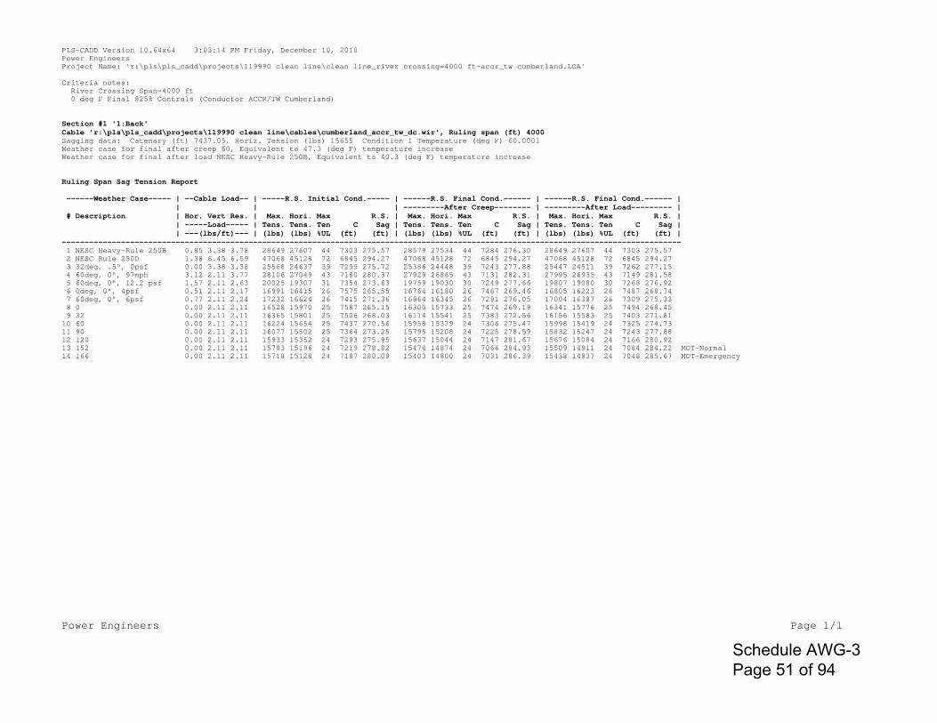
Power Engineers Page 1/1
PLS-CADD Version 10.64x64 3:03:14 PM Friday, December 10, 2010Power EngineersProject Name: 'r:\pls\pls_cadd\projects\119990 clean line\clean line_river crossing=4000 ft-accr_tw cumberland.LOA'
Criteria notes: River Crossing Span=4000 ft 0 deg F Final @25% Controls (Conductor ACCR/TW Cumberland)
Section #1 '1:Back'Cable 'r:\pls\pls_cadd\projects\119990 clean line\cables\cumberland_accr_tw_dc.wir', Ruling span (ft) 4000Sagging data: Catenary (ft) 7437.05, Horiz. Tension (lbs) 15655 Condition I Temperature (deg F) 60.0001Weather case for final after creep 60, Equivalent to 47.3 (deg F) temperature increaseWeather case for final after load NESC Heavy-Rule 250B, Equivalent to 40.3 (deg F) temperature increase
Ruling Span Sag Tension Report
------Weather Case----- | --Cable Load-- | -----R.S. Initial Cond.----- | ------R.S. Final Cond.------ | ------R.S. Final Cond.------ | | | | ---------After Creep-------- | ---------After Load--------- | # Description | Hor. Vert Res. | Max. Hori. Max R.S. | Max. Hori. Max R.S. | Max. Hori. Max R.S. | | -----Load----- | Tens. Tens. Ten C Sag | Tens. Tens. Ten C Sag | Tens. Tens. Ten C Sag | | ---(lbs/ft)--- | (lbs) (lbs) %UL (ft) (ft) | (lbs) (lbs) %UL (ft) (ft) | (lbs) (lbs) %UL (ft) (ft) |---------------------------------------------------------------------------------------------------------------------------------------- 1 NESC Heavy-Rule 250B 0.85 3.38 3.78 28649 27607 44 7303 275.57 28579 27534 44 7284 276.30 28649 27607 44 7303 275.57 2 NESC Rule 250D 1.38 6.45 6.59 47068 45128 72 6845 294.27 47068 45128 72 6845 294.27 47068 45128 72 6845 294.27 3 32deg, .5", 0psf 0.00 3.38 3.38 25568 24637 39 7299 275.72 25386 24448 39 7243 277.88 25447 24511 39 7262 277.15 4 60deg, 0", 97mph 3.12 2.11 3.77 28106 27049 43 7180 280.37 27929 26865 43 7131 282.31 27995 26935 43 7149 281.58 5 60deg, 0", 12.2 psf 1.57 2.11 2.63 20025 19307 31 7354 273.63 19759 19030 30 7249 277.66 19807 19080 30 7268 276.92 6 0deg, 0", 4psf 0.51 2.11 2.17 16991 16415 26 7575 265.55 16764 16180 26 7467 269.46 16805 16223 26 7487 268.74 7 60deg, 0", 6psf 0.77 2.11 2.24 17232 16624 26 7415 271.36 16964 16345 26 7291 276.05 17004 16387 26 7309 275.33 8 0 0.00 2.11 2.11 16528 15970 25 7587 265.15 16300 15733 25 7474 269.19 16341 15776 25 7494 268.45 9 32 0.00 2.11 2.11 16365 15801 25 7506 268.03 16114 15541 25 7383 272.56 16156 15583 25 7403 271.81 10 60 0.00 2.11 2.11 16224 15654 25 7437 270.56 15958 15379 24 7306 275.47 15998 15419 24 7325 274.73 11 90 0.00 2.11 2.11 16077 15502 25 7364 273.25 15795 15208 24 7225 278.59 15832 15247 24 7243 277.88 12 120 0.00 2.11 2.11 15933 15352 24 7293 275.95 15637 15044 24 7147 281.67 15676 15084 24 7166 280.92 13 152 0.00 2.11 2.11 15783 15196 24 7219 278.82 15474 14874 24 7066 284.93 15509 14911 24 7084 284.22 MOT-Normal14 166 0.00 2.11 2.11 15718 15128 24 7187 280.09 15403 14800 24 7031 286.39 15438 14837 24 7048 285.67 MOT-Emergency
Schedule AWG-3 Page 51 of 94
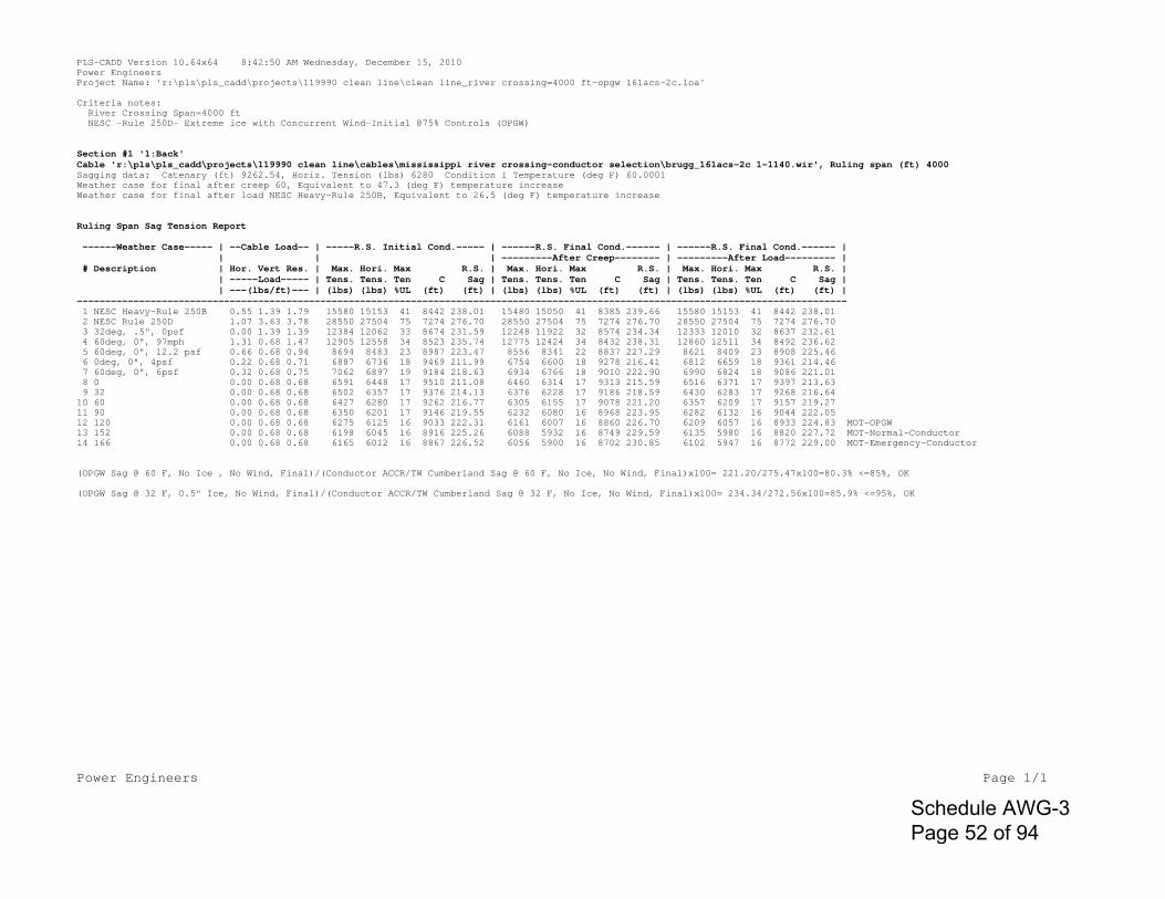
Power Engineers Page 1/1
PLS-CADD Version 10.64x64 8:42:50 AM Wednesday, December 15, 2010Power EngineersProject Name: 'r:\pls\pls_cadd\projects\119990 clean line\clean line_river crossing=4000 ft-opgw 161acs-2c.loa'
Criteria notes: River Crossing Span=4000 ft NESC -Rule 250D- Extreme ice with Concurrent Wind-Initial @75% Controls (OPGW)
Section #1 '1:Back'Cable 'r:\pls\pls_cadd\projects\119990 clean line\cables\mississippi river crossing-conductor selection\brugg_161acs-2c 1-1140.wir', Ruling span (ft) 4000Sagging data: Catenary (ft) 9262.54, Horiz. Tension (lbs) 6280 Condition I Temperature (deg F) 60.0001Weather case for final after creep 60, Equivalent to 47.3 (deg F) temperature increaseWeather case for final after load NESC Heavy-Rule 250B, Equivalent to 26.5 (deg F) temperature increase
Ruling Span Sag Tension Report
------Weather Case----- | --Cable Load-- | -----R.S. Initial Cond.----- | ------R.S. Final Cond.------ | ------R.S. Final Cond.------ | | | | ---------After Creep-------- | ---------After Load--------- | # Description | Hor. Vert Res. | Max. Hori. Max R.S. | Max. Hori. Max R.S. | Max. Hori. Max R.S. | | -----Load----- | Tens. Tens. Ten C Sag | Tens. Tens. Ten C Sag | Tens. Tens. Ten C Sag | | ---(lbs/ft)--- | (lbs) (lbs) %UL (ft) (ft) | (lbs) (lbs) %UL (ft) (ft) | (lbs) (lbs) %UL (ft) (ft) |---------------------------------------------------------------------------------------------------------------------------------------- 1 NESC Heavy-Rule 250B 0.55 1.39 1.79 15580 15153 41 8442 238.01 15480 15050 41 8385 239.66 15580 15153 41 8442 238.01 2 NESC Rule 250D 1.07 3.63 3.78 28550 27504 75 7274 276.70 28550 27504 75 7274 276.70 28550 27504 75 7274 276.70 3 32deg, .5", 0psf 0.00 1.39 1.39 12384 12062 33 8674 231.59 12248 11922 32 8574 234.34 12333 12010 32 8637 232.61 4 60deg, 0", 97mph 1.31 0.68 1.47 12905 12558 34 8523 235.74 12775 12424 34 8432 238.31 12860 12511 34 8492 236.62 5 60deg, 0", 12.2 psf 0.66 0.68 0.94 8694 8483 23 8987 223.47 8556 8341 22 8837 227.29 8621 8409 23 8908 225.46 6 0deg, 0", 4psf 0.22 0.68 0.71 6887 6736 18 9469 211.99 6754 6600 18 9278 216.41 6812 6659 18 9361 214.46 7 60deg, 0", 6psf 0.32 0.68 0.75 7062 6897 19 9184 218.63 6934 6766 18 9010 222.90 6990 6824 18 9086 221.01 8 0 0.00 0.68 0.68 6591 6448 17 9510 211.08 6460 6314 17 9313 215.59 6516 6371 17 9397 213.63 9 32 0.00 0.68 0.68 6502 6357 17 9376 214.13 6376 6228 17 9186 218.59 6430 6283 17 9268 216.64 10 60 0.00 0.68 0.68 6427 6280 17 9262 216.77 6305 6155 17 9078 221.20 6357 6209 17 9157 219.27 11 90 0.00 0.68 0.68 6350 6201 17 9146 219.55 6232 6080 16 8968 223.95 6282 6132 16 9044 222.05 12 120 0.00 0.68 0.68 6275 6125 16 9033 222.31 6161 6007 16 8860 226.70 6209 6057 16 8933 224.83 MOT-OPGW13 152 0.00 0.68 0.68 6198 6045 16 8916 225.26 6088 5932 16 8749 229.59 6135 5980 16 8820 227.72 MOT-Normal-Conductor14 166 0.00 0.68 0.68 6165 6012 16 8867 226.52 6056 5900 16 8702 230.85 6102 5947 16 8772 229.00 MOT-Emergency-Conductor
(OPGW Sag @ 60 F, No Ice , No Wind, Final)/(Conductor ACCR/TW Cumberland Sag @ 60 F, No Ice, No Wind, Final)x100= 221.20/275.47x100=80.3% <=85%, OK
(OPGW Sag @ 32 F, 0.5" Ice, No Wind, Final)/(Conductor ACCR/TW Cumberland Sag @ 32 F, No Ice, No Wind, Final)x100= 234.34/272.56x100=85.9% <=95%, OK
Schedule AWG-3 Page 52 of 94
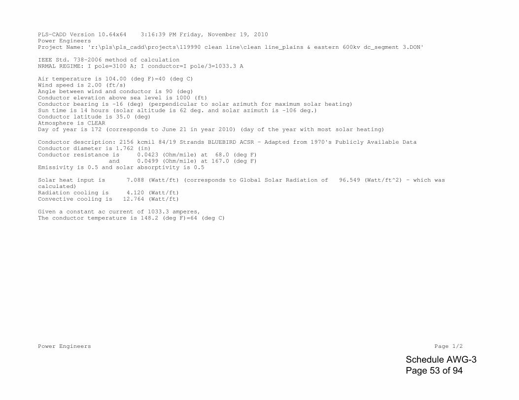
Power Engineers Page 1/2
PLS-CADD Version 10.64x64 3:16:39 PM Friday, November 19, 2010Power EngineersProject Name: 'r:\pls\pls_cadd\projects\119990 clean line\clean line_plains & eastern 600kv dc_segment 3.DON'
IEEE Std. 738-2006 method of calculationNRMAL REGIME: I pole=3100 A; I conductor=I pole/3=1033.3 A
Air temperature is 104.00 (deg F)=40 (deg C)Wind speed is 2.00 (ft/s)Angle between wind and conductor is 90 (deg)Conductor elevation above sea level is 1000 (ft)Conductor bearing is -16 (deg) (perpendicular to solar azimuth for maximum solar heating)Sun time is 14 hours (solar altitude is 62 deg. and solar azimuth is -106 deg.)Conductor latitude is 35.0 (deg)Atmosphere is CLEARDay of year is 172 (corresponds to June 21 in year 2010) (day of the year with most solar heating)
Conductor description: 2156 kcmil 84/19 Strands BLUEBIRD ACSR - Adapted from 1970's Publicly Available DataConductor diameter is 1.762 (in)Conductor resistance is 0.0423 (Ohm/mile) at 68.0 (deg F) and 0.0499 (Ohm/mile) at 167.0 (deg F)Emissivity is 0.5 and solar absorptivity is 0.5
Solar heat input is 7.088 (Watt/ft) (corresponds to Global Solar Radiation of 96.549 (Watt/ft^2) - which was calculated)Radiation cooling is 4.120 (Watt/ft)Convective cooling is 12.764 (Watt/ft)
Given a constant ac current of 1033.3 amperes,The conductor temperature is 148.2 (deg F)=64 (deg C)
Schedule AWG-3 Page 53 of 94
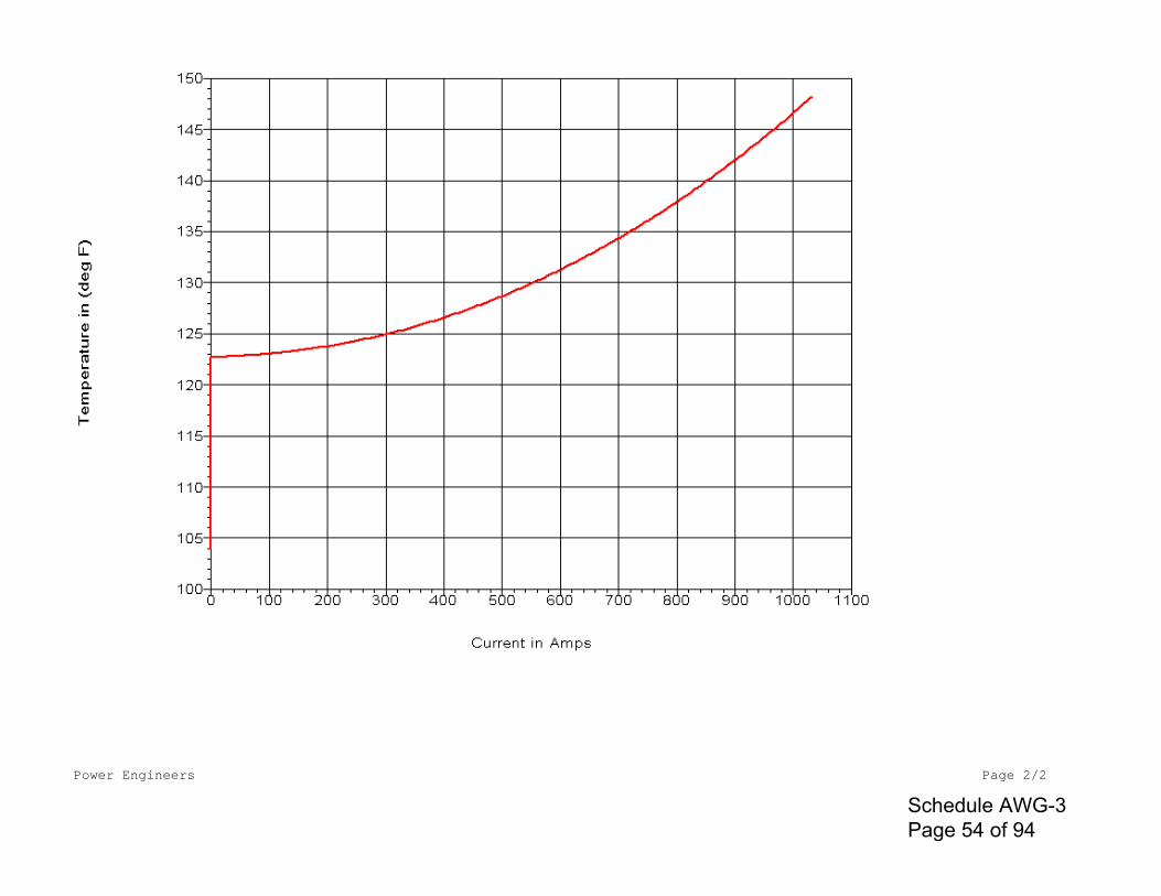
Power Engineers Page 2/2
Schedule AWG-3 Page 54 of 94

Power Engineers Page 1/2
PLS-CADD Version 10.64x64 2:58:27 PM Friday, November 19, 2010Power EngineersProject Name: 'r:\pls\pls_cadd\projects\119990 clean line\clean line_plains & eastern 600kv dc_segment 3.DON'
IEEE Std. 738-2006 method of calculation
EMERGENCY REGIME: I pole=3720 A; I conductor=I pole/3=1240 A (20% over Normal Regime: I pole=3100 A; I conductor=I pole/3=1033.3 A)
Air temperature is 104.00 (deg F)Wind speed is 2.00 (ft/s)Angle between wind and conductor is 90 (deg)Conductor elevation above sea level is 1000 (ft)Conductor bearing is -16 (deg) (perpendicular to solar azimuth for maximum solar heating)Sun time is 14 hours (solar altitude is 62 deg. and solar azimuth is -106 deg.)Conductor latitude is 35.0 (deg)Atmosphere is CLEARDay of year is 172 (corresponds to June 21 in year 2010) (day of the year with most solar heating)
Conductor description: 2156 kcmil 84/19 Strands BLUEBIRD ACSR - Adapted from 1970's Publicly Available DataConductor diameter is 1.762 (in)Conductor resistance is 0.0423 (Ohm/mile) at 68.0 (deg F) and 0.0499 (Ohm/mile) at 167.0 (deg F)Emissivity is 0.5 and solar absorptivity is 0.5
Solar heat input is 7.088 (Watt/ft) (corresponds to Global Solar Radiation of 96.549 (Watt/ft^2) - which was calculated)Radiation cooling is 5.359 (Watt/ft)Convective cooling is 16.099 (Watt/ft)
Given a constant ac current of 1240.0 amperes,The conductor temperature is 159.8 (deg F)=71 (deg C)
Schedule AWG-3 Page 55 of 94
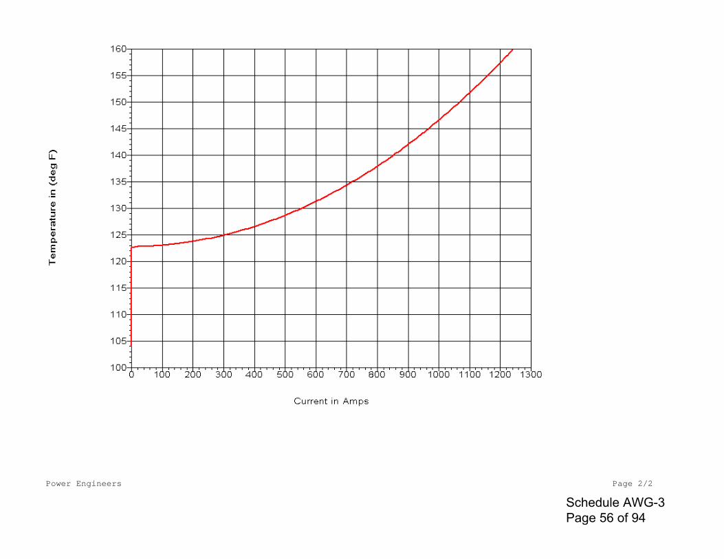
Power Engineers Page 2/2
Schedule AWG-3 Page 56 of 94
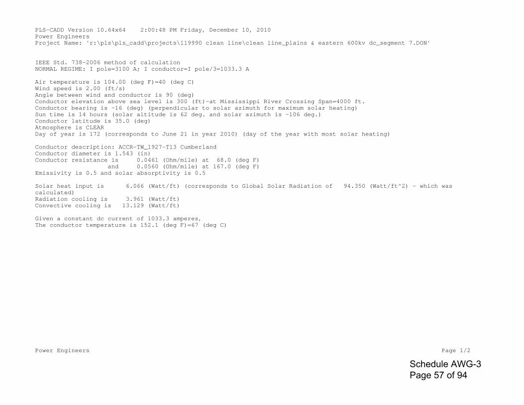
Power Engineers Page 1/2
PLS-CADD Version 10.64x64 2:00:48 PM Friday, December 10, 2010Power EngineersProject Name: 'r:\pls\pls_cadd\projects\119990 clean line\clean line_plains & eastern 600kv dc_segment 7.DON'
IEEE Std. 738-2006 method of calculationNORMAL REGIME: I pole=3100 A; I conductor=I pole/3=1033.3 A
Air temperature is 104.00 (deg F)=40 (deg C)Wind speed is 2.00 (ft/s)Angle between wind and conductor is 90 (deg)Conductor elevation above sea level is 300 (ft)-at Mississippi River Crossing Span=4000 ft.Conductor bearing is -16 (deg) (perpendicular to solar azimuth for maximum solar heating)Sun time is 14 hours (solar altitude is 62 deg. and solar azimuth is -106 deg.)Conductor latitude is 35.0 (deg)Atmosphere is CLEARDay of year is 172 (corresponds to June 21 in year 2010) (day of the year with most solar heating)
Conductor description: ACCR-TW_1927-T13 CumberlandConductor diameter is 1.543 (in)Conductor resistance is 0.0461 (Ohm/mile) at 68.0 (deg F) and 0.0560 (Ohm/mile) at 167.0 (deg F)Emissivity is 0.5 and solar absorptivity is 0.5
Solar heat input is 6.066 (Watt/ft) (corresponds to Global Solar Radiation of 94.350 (Watt/ft^2) - which was calculated)Radiation cooling is 3.961 (Watt/ft)Convective cooling is 13.129 (Watt/ft)
Given a constant dc current of 1033.3 amperes,The conductor temperature is 152.1 (deg F)=67 (deg C)
Schedule AWG-3 Page 57 of 94
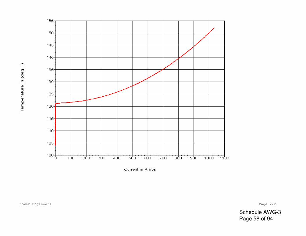
Power Engineers Page 2/2
Schedule AWG-3 Page 58 of 94
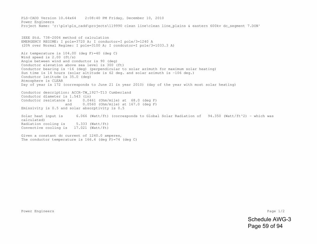
Power Engineers Page 1/2
PLS-CADD Version 10.64x64 2:08:40 PM Friday, December 10, 2010Power EngineersProject Name: 'r:\pls\pls_cadd\projects\119990 clean line\clean line_plains & eastern 600kv dc_segment 7.DON'
IEEE Std. 738-2006 method of calculationEMERGENCY REGIME: I pole=3720 A; I conductor=I pole/3=1240 A(20% over Normal Regime: I pole=3100 A; I condcutor=I pole/3=1033.3 A)
Air temperature is 104.00 (deg F)=40 (deg C)Wind speed is 2.00 (ft/s)Angle between wind and conductor is 90 (deg)Conductor elevation above sea level is 300 (ft)Conductor bearing is -16 (deg) (perpendicular to solar azimuth for maximum solar heating)Sun time is 14 hours (solar altitude is 62 deg. and solar azimuth is -106 deg.)Conductor latitude is 35.0 (deg)Atmosphere is CLEARDay of year is 172 (corresponds to June 21 in year 2010) (day of the year with most solar heating)
Conductor description: ACCR-TW_1927-T13 CumberlandConductor diameter is 1.543 (in)Conductor resistance is 0.0461 (Ohm/mile) at 68.0 (deg F) and 0.0560 (Ohm/mile) at 167.0 (deg F)Emissivity is 0.5 and solar absorptivity is 0.5
Solar heat input is 6.066 (Watt/ft) (corresponds to Global Solar Radiation of 94.350 (Watt/ft^2) - which was calculated)Radiation cooling is 5.333 (Watt/ft)Convective cooling is 17.021 (Watt/ft)
Given a constant dc current of 1240.0 amperes,The conductor temperature is 166.4 (deg F)=74 (deg C)
Schedule AWG-3 Page 59 of 94
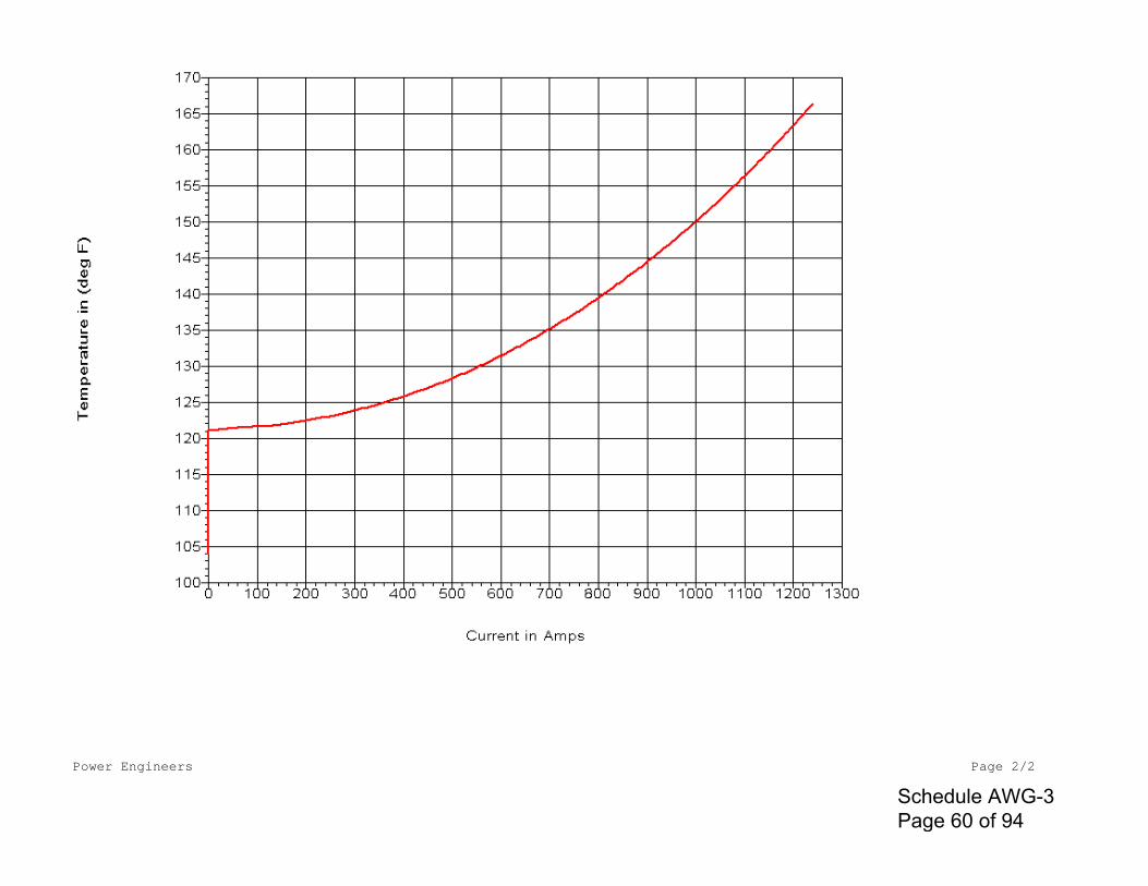
Power Engineers Page 2/2
Schedule AWG-3 Page 60 of 94
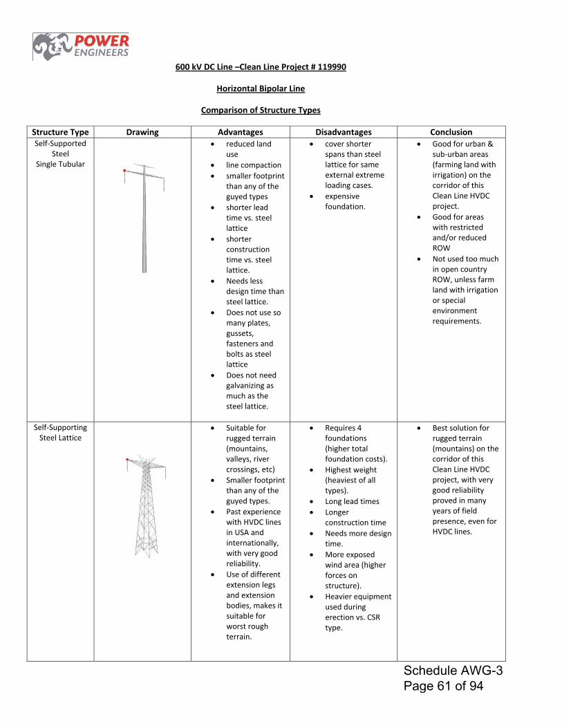
600 kV DC Line –Clean Line Project # 119990
Horizontal Bipolar Line
Comparison of Structure Types
Structure Type Drawing Advantages Disadvantages Conclusion Self‐Supported
Steel Single Tubular
reduced land use
line compaction
smaller footprint than any of the guyed types
shorter lead time vs. steel lattice
shorter construction time vs. steel lattice.
Needs less design time than steel lattice.
Does not use so many plates, gussets, fasteners and bolts as steel lattice
Does not need galvanizing as much as the steel lattice.
cover shorter spans than steel lattice for same external extreme loading cases.
expensive foundation.
Good for urban & sub‐urban areas (farming land with irrigation) on the corridor of this Clean Line HVDC project.
Good for areas with restricted and/or reduced ROW
Not used too much in open country ROW, unless farm land with irrigation or special environment requirements.
Self‐Supporting Steel Lattice
Suitable for rugged terrain (mountains, valleys, river crossings, etc)
Smaller footprint than any of the guyed types.
Past experience with HVDC lines in USA and internationally, with very good reliability.
Use of different extension legs and extension bodies, makes it suitable for worst rough terrain.
Requires 4 foundations (higher total foundation costs).
Highest weight (heaviest of all types).
Long lead times
Longer construction time
Needs more design time.
More exposed wind area (higher forces on structure).
Heavier equipment used during erection vs. CSR type.
Best solution for rugged terrain (mountains) on the corridor of this Clean Line HVDC project, with very good reliability proved in many years of field presence, even for HVDC lines.
Schedule AWG-3 Page 61 of 94
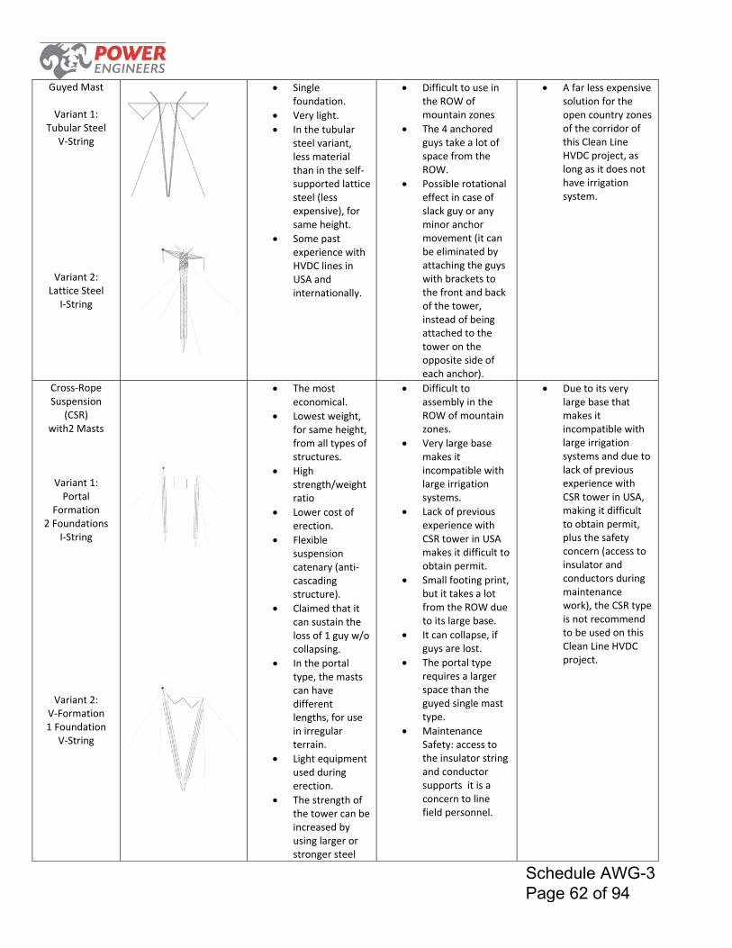
Guyed Mast
Variant 1:
Tubular Steel V‐String
Variant 2: Lattice Steel
I‐String
Single foundation.
Very light.
In the tubular steel variant, less material than in the self‐supported lattice steel (less expensive), for same height.
Some past experience with HVDC lines in USA and internationally.
Difficult to use in the ROW of mountain zones
The 4 anchored guys take a lot of space from the ROW.
Possible rotational effect in case of slack guy or any minor anchor movement (it can be eliminated by attaching the guys with brackets to the front and back of the tower, instead of being attached to the tower on the opposite side of each anchor).
A far less expensive solution for the open country zones of the corridor of this Clean Line HVDC project, as long as it does not have irrigation system.
Cross‐Rope Suspension
(CSR) with2 Masts
Variant 1: Portal
Formation 2 Foundations
I‐String
Variant 2:
V‐Formation 1 Foundation
V‐String
The most economical.
Lowest weight, for same height, from all types of structures.
High strength/weight ratio
Lower cost of erection.
Flexible suspension catenary (anti‐cascading structure).
Claimed that it can sustain the loss of 1 guy w/o collapsing.
In the portal type, the masts can have different lengths, for use in irregular terrain.
Light equipment used during erection.
The strength of the tower can be increased by using larger or stronger steel
Difficult to assembly in the ROW of mountain zones.
Very large base makes it incompatible with large irrigation systems.
Lack of previous experience with CSR tower in USA makes it difficult to obtain permit.
Small footing print, but it takes a lot from the ROW due to its large base.
It can collapse, if guys are lost.
The portal type requires a larger space than the guyed single mast type.
Maintenance Safety: access to the insulator string and conductor supports it is a concern to line field personnel.
Due to its very large base that makes it incompatible with large irrigation systems and due to lack of previous experience with CSR tower in USA, making it difficult to obtain permit, plus the safety concern (access to insulator and conductors during maintenance work), the CSR type is not recommend to be used on this Clean Line HVDC project.
Schedule AWG-3 Page 62 of 94
cables.
Used extensively in international HVAC lines 400 kV‐ 800 KV (Brazil, Argentina, South Africa, Canada).
Schedule AWG-3 Page 63 of 94
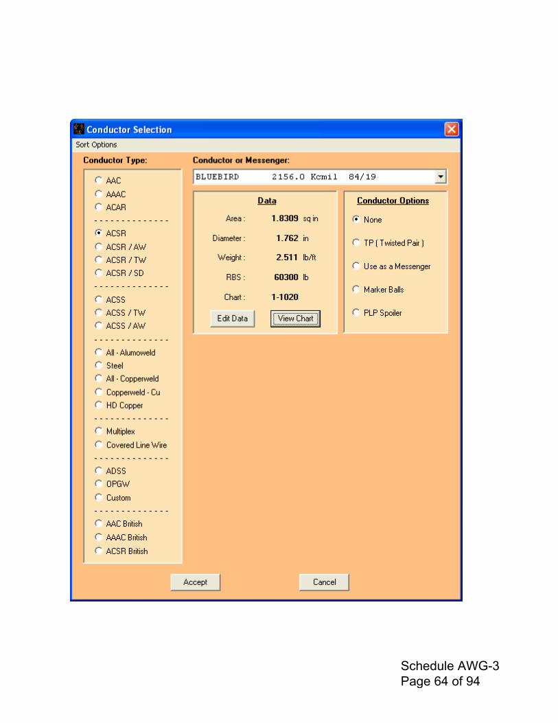
Schedule AWG-3 Page 64 of 94
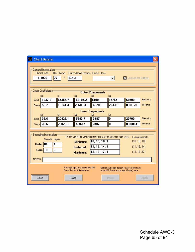
Schedule AWG-3 Page 65 of 94
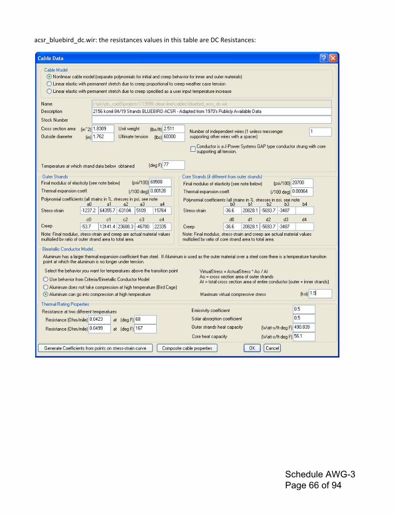
acsr_bluebird_dc.wir: the resistances values in this table are DC Resistances:
Schedule AWG-3 Page 66 of 94
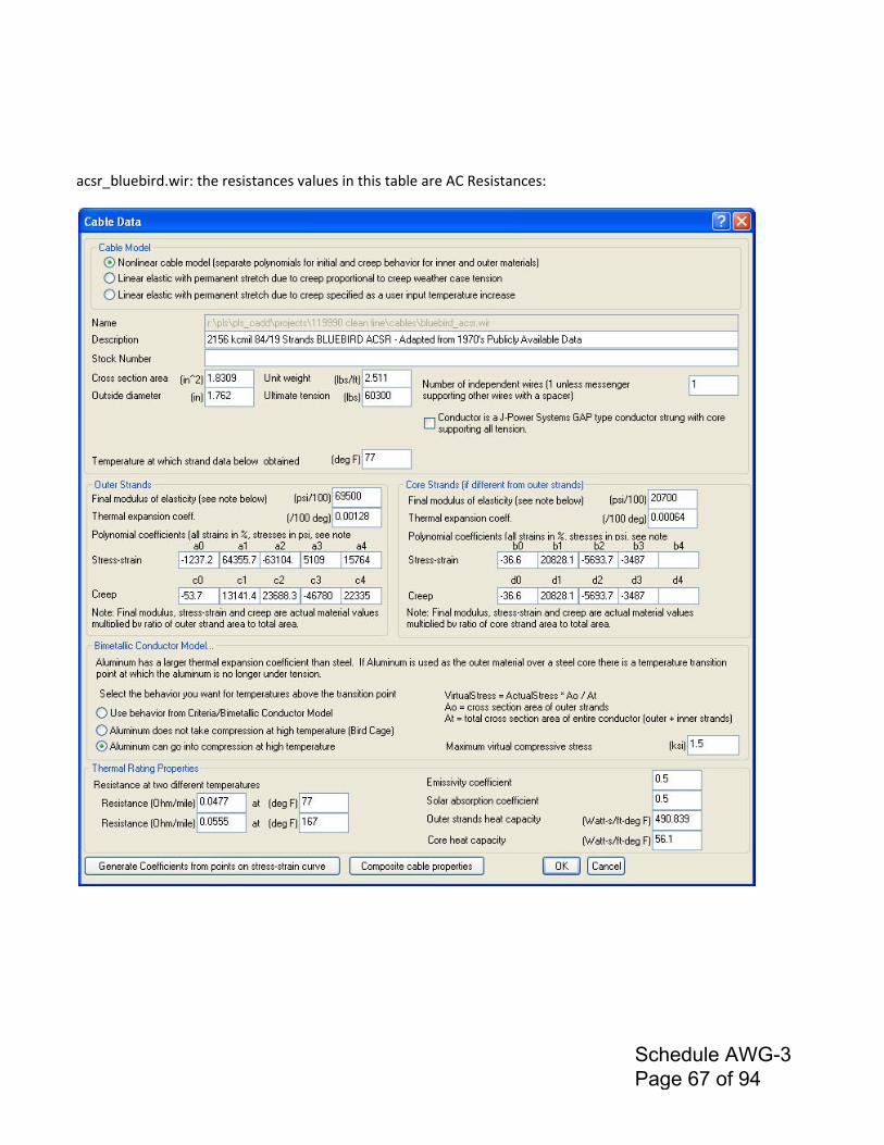
acsr_bluebird.wir: the resistances values in this table are AC Resistances:
Schedule AWG-3 Page 67 of 94
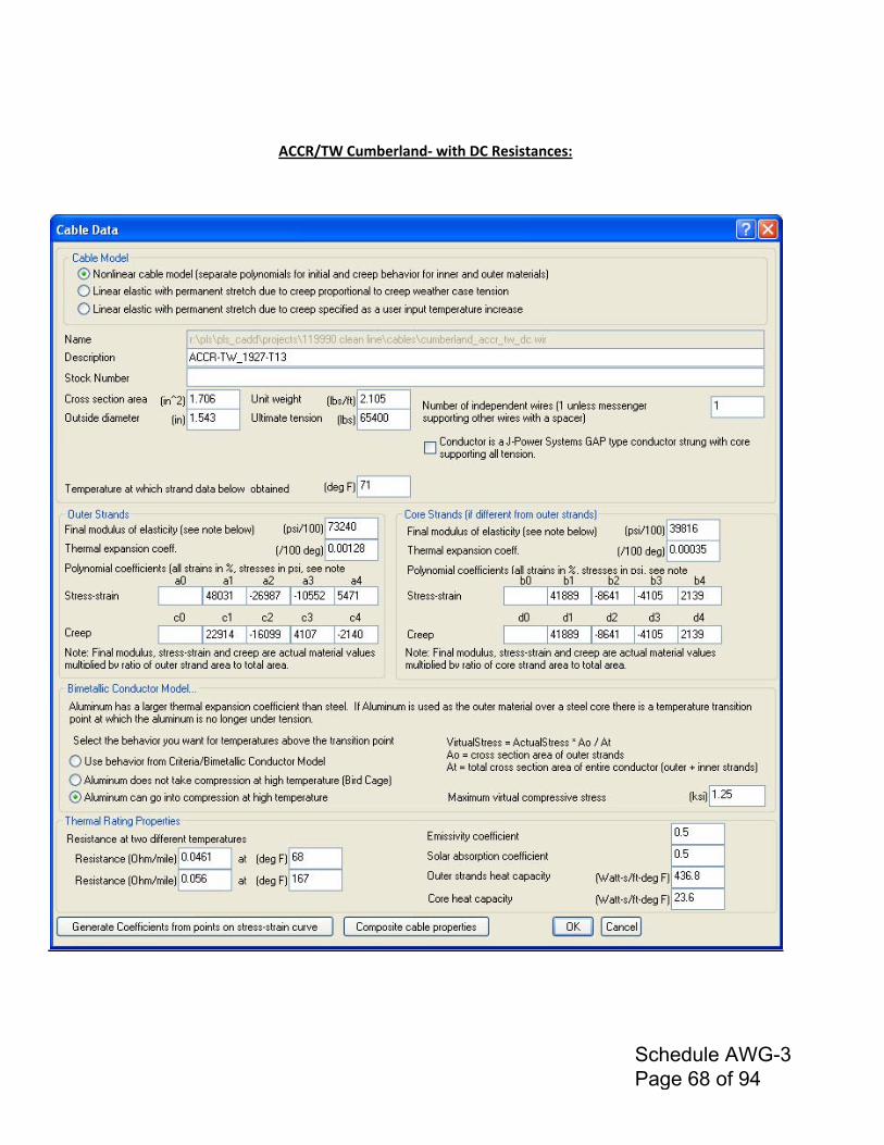
ACCR/TW Cumberland‐ with DC Resistances:
Schedule AWG-3 Page 68 of 94
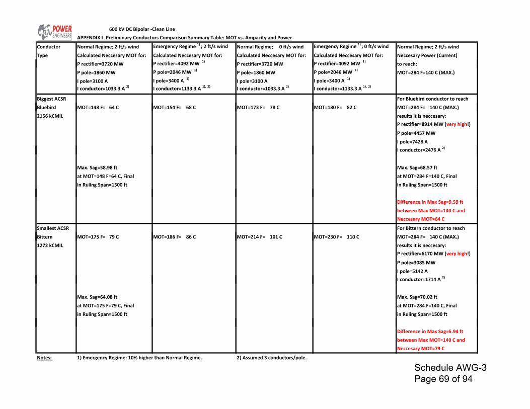
600 kV DC Bipolar ‐Clean Line
APPENDIX I‐ Preliminary Conductors Comparison Summary Table: MOT vs. Ampacity and Power
Conductor Normal Regime; 2 ft/s wind Emergency Regime 1) ; 2 ft/s wind Normal Regime; 0 ft/s wind Emergency Regime 1) ; 0 ft/s wind Normal Regime; 2 ft/s wind
Type Calculated Neccesary MOT for: Calculated Neccesary MOT for: Calculated Neccesary MOT for: Calculated Neccesary MOT for: Neccesary Power (Current)
P rectifier=3720 MW P rectifier=4092 MW 1) P rectifier=3720 MW P rectifier=4092 MW 1)
to reach:
P pole=1860 MW P pole=2046 MW 1) P pole=1860 MW P pole=2046 MW 1) MOT=284 F=140 C (MAX.)
I pole=3100 A I pole=3400 A 1) I pole=3100 A I pole=3400 A 1)
I conductor=1033.3 A 2) I conductor=1133.3 A 1), 2) I conductor=1033.3 A 2) I conductor=1133.3 A 1), 2)
Biggest ACSR For Bluebird conductor to reach
Bluebird MOT=148 F= 64 C MOT=154 F= 68 C MOT=173 F= 78 C MOT=180 F= 82 C MOT=284 F= 140 C (MAX.)( )
2156 kCMIL results it is neccesary:
P rectifier=8914 MW (very high!)
P pole=4457 MW
I pole=7428 A
I conductor=2476 A 2)
Max. Sag=58.98 ft Max. Sag=68.57 ft
at MOT=148 F=64 C, Final at MOT=284 F=140 C, Final
in Ruling Span=1500 ft in Ruling Span=1500 ft
Difference in Max Sag=9.59 ft
between Max MOT=140 C and
Neccesary MOT=64 C
Smallest ACSR For Bittern conductor to reach
Bittern MOT=175 F= 79 C MOT=186 F= 86 C MOT=214 F= 101 C MOT=230 F= 110 C MOT=284 F= 140 C (MAX.)Bittern MOT 175 F 79 C MOT 186 F 86 C MOT 214 F 101 C MOT 230 F 110 C MOT 284 F 140 C (MAX.)
1272 kCMIL results it is neccesary:
P rectifier=6170 MW (very high!)
P pole=3085 MW
I pole=5142 A
I conductor=1714 A 2)I conductor 1714 A
Max. Sag=64.08 ft Max. Sag=70.02 ft
at MOT=175 F=79 C, Final at MOT=284 F=140 C, Final
in Ruling Span=1500 ft in Ruling Span=1500 ft
Difference in Max Sag=5.94 ft
between Max MOT=140 C and
Neccesary MOT=79 C
Notes: 1) Emergency Regime: 10% higher than Normal Regime. 2) Assumed 3 conductors/pole.
Schedule AWG-3 Page 69 of 94
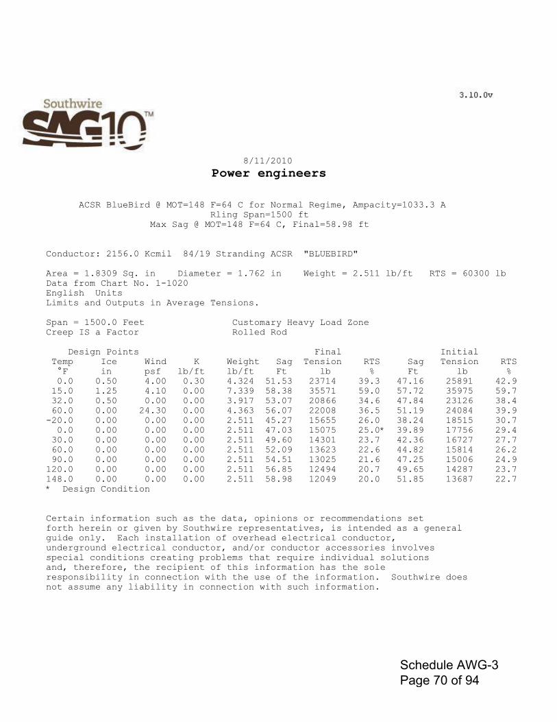
8/11/2010
Power engineers
ACSR BlueBird @ MOT=148 F=64 C for Normal Regime, Ampacity=1033.3 A Rling Span=1500 ft Max Sag @ MOT=148 F=64 C, Final=58.98 ft
Conductor: 2156.0 Kcmil 84/19 Stranding ACSR "BLUEBIRD"
Area = 1.8309 Sq. in Diameter = 1.762 in Weight = 2.511 lb/ft RTS = 60300 lb Data from Chart No. 1-1020 English Units Limits and Outputs in Average Tensions.
Span = 1500.0 Feet Customary Heavy Load Zone Creep IS a Factor Rolled Rod
Design Points Final Initial Temp Ice Wind K Weight Sag Tension RTS Sag Tension RTS °F in psf lb/ft lb/ft Ft lb % Ft lb % 0.0 0.50 4.00 0.30 4.324 51.53 23714 39.3 47.16 25891 42.9 15.0 1.25 4.10 0.00 7.339 58.38 35571 59.0 57.72 35975 59.7 32.0 0.50 0.00 0.00 3.917 53.07 20866 34.6 47.84 23126 38.4 60.0 0.00 24.30 0.00 4.363 56.07 22008 36.5 51.19 24084 39.9 -20.0 0.00 0.00 0.00 2.511 45.27 15655 26.0 38.24 18515 30.7 0.0 0.00 0.00 0.00 2.511 47.03 15075 25.0* 39.89 17756 29.4 30.0 0.00 0.00 0.00 2.511 49.60 14301 23.7 42.36 16727 27.7 60.0 0.00 0.00 0.00 2.511 52.09 13623 22.6 44.82 15814 26.2 90.0 0.00 0.00 0.00 2.511 54.51 13025 21.6 47.25 15006 24.9 120.0 0.00 0.00 0.00 2.511 56.85 12494 20.7 49.65 14287 23.7 148.0 0.00 0.00 0.00 2.511 58.98 12049 20.0 51.85 13687 22.7 * Design Condition
Certain information such as the data, opinions or recommendations set forth herein or given by Southwire representatives, is intended as a general guide only. Each installation of overhead electrical conductor, underground electrical conductor, and/or conductor accessories involves special conditions creating problems that require individual solutions and, therefore, the recipient of this information has the sole responsibility in connection with the use of the information. Southwire does not assume any liability in connection with such information.�
Schedule AWG-3 Page 70 of 94
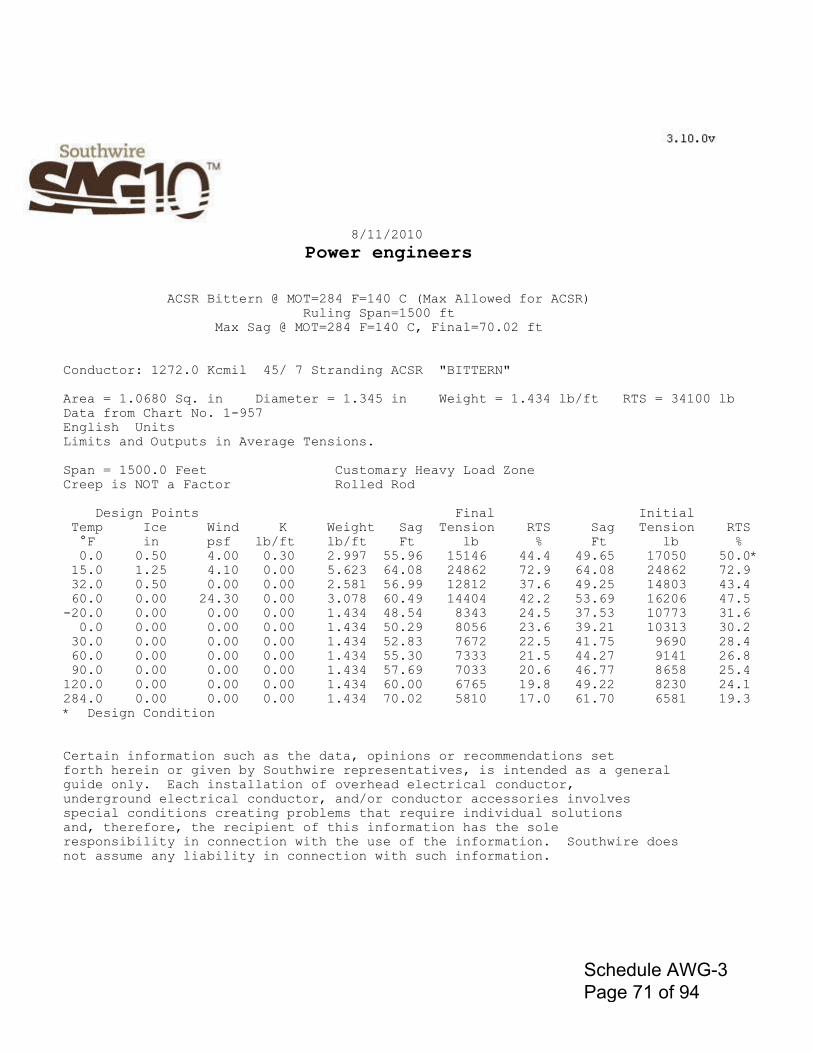
8/11/2010
Power engineers
ACSR Bittern @ MOT=284 F=140 C (Max Allowed for ACSR) Ruling Span=1500 ft Max Sag @ MOT=284 F=140 C, Final=70.02 ft
Conductor: 1272.0 Kcmil 45/ 7 Stranding ACSR "BITTERN"
Area = 1.0680 Sq. in Diameter = 1.345 in Weight = 1.434 lb/ft RTS = 34100 lb Data from Chart No. 1-957 English Units Limits and Outputs in Average Tensions.
Span = 1500.0 Feet Customary Heavy Load Zone Creep is NOT a Factor Rolled Rod
Design Points Final Initial Temp Ice Wind K Weight Sag Tension RTS Sag Tension RTS °F in psf lb/ft lb/ft Ft lb % Ft lb % 0.0 0.50 4.00 0.30 2.997 55.96 15146 44.4 49.65 17050 50.0* 15.0 1.25 4.10 0.00 5.623 64.08 24862 72.9 64.08 24862 72.9 32.0 0.50 0.00 0.00 2.581 56.99 12812 37.6 49.25 14803 43.4 60.0 0.00 24.30 0.00 3.078 60.49 14404 42.2 53.69 16206 47.5 -20.0 0.00 0.00 0.00 1.434 48.54 8343 24.5 37.53 10773 31.6 0.0 0.00 0.00 0.00 1.434 50.29 8056 23.6 39.21 10313 30.2 30.0 0.00 0.00 0.00 1.434 52.83 7672 22.5 41.75 9690 28.4 60.0 0.00 0.00 0.00 1.434 55.30 7333 21.5 44.27 9141 26.8 90.0 0.00 0.00 0.00 1.434 57.69 7033 20.6 46.77 8658 25.4 120.0 0.00 0.00 0.00 1.434 60.00 6765 19.8 49.22 8230 24.1 284.0 0.00 0.00 0.00 1.434 70.02 5810 17.0 61.70 6581 19.3 * Design Condition
Certain information such as the data, opinions or recommendations set forth herein or given by Southwire representatives, is intended as a general guide only. Each installation of overhead electrical conductor, underground electrical conductor, and/or conductor accessories involves special conditions creating problems that require individual solutions and, therefore, the recipient of this information has the sole responsibility in connection with the use of the information. Southwire does not assume any liability in connection with such information.�
Schedule AWG-3 Page 71 of 94

8/11/2010
Power engineers
ACSR Bittern @ MOT=175 F=79 C for Normal Regime, Ampacity=1033.3 A Ruling Span=1500 ft Max Sag @ MOT=175 F=79 C, Final=62.10 ft
Conductor: 1272.0 Kcmil 45/ 7 Stranding ACSR "BITTERN"
Area = 1.0680 Sq. in Diameter = 1.345 in Weight = 1.434 lb/ft RTS = 34100 lb Data from Chart No. 1-957 English Units Limits and Outputs in Average Tensions.
Span = 1500.0 Feet Customary Heavy Load Zone Creep is NOT a Factor Rolled Rod
Design Points Final Initial Temp Ice Wind K Weight Sag Tension RTS Sag Tension RTS °F in psf lb/ft lb/ft Ft lb % Ft lb % 0.0 0.50 4.00 0.30 2.997 55.96 15146 44.4 49.65 17050 50.0* 15.0 1.25 4.10 0.00 5.623 64.08 24862 72.9 64.08 24862 72.9 32.0 0.50 0.00 0.00 2.581 56.99 12812 37.6 49.25 14803 43.4 60.0 0.00 24.30 0.00 3.078 60.49 14404 42.2 53.69 16206 47.5 -20.0 0.00 0.00 0.00 1.434 48.54 8343 24.5 37.53 10773 31.6 0.0 0.00 0.00 0.00 1.434 50.29 8056 23.6 39.21 10313 30.2 30.0 0.00 0.00 0.00 1.434 52.83 7672 22.5 41.75 9690 28.4 60.0 0.00 0.00 0.00 1.434 55.30 7333 21.5 44.27 9141 26.8 90.0 0.00 0.00 0.00 1.434 57.69 7033 20.6 46.77 8658 25.4 120.0 0.00 0.00 0.00 1.434 60.00 6765 19.8 49.22 8230 24.1 148.0 0.00 0.00 0.00 1.434 62.10 6539 19.2 51.46 7874 23.1 * Design Condition
Certain information such as the data, opinions or recommendations set forth herein or given by Southwire representatives, is intended as a general guide only. Each installation of overhead electrical conductor, underground electrical conductor, and/or conductor accessories involves special conditions creating problems that require individual solutions and, therefore, the recipient of this information has the sole responsibility in connection with the use of the information. Southwire does not assume any liability in connection with such information.�
Schedule AWG-3 Page 72 of 94

PLS-CADD Version 10.60x64 3:01:58 PM Tuesday, August 10, 2010 Power Engineers IEEE Std. 738-2006 method of calculation Air temperature is 104.00 (deg F)=40 (deg C) Wind speed is 2.00 (ft/s) Angle between wind and conductor is 90 (deg) Conductor elevation above sea level is 1000 (ft) Conductor bearing is -7 (deg) (perpendicular to solar azimuth for maximum solar heating) Sun time is 14 hours (solar altitude is 63 deg. and solar azimuth is -97 deg.) Conductor latitude is 30.0 (deg) Atmosphere is CLEAR Day of year is 172 (corresponds to June 21 in year 2010) (day of the year with most solar heating) Conductor description: 2156 kcmil 84/19 Strands BLUEBIRD ACSR - Adapted from 1970's Publicly Available Data Conductor diameter is 1.762 (in) Conductor resistance is 0.0423 (Ohm/mile) at 68.0 (deg F) and 0.0499 (Ohm/mile) at 167.0 (deg F) Emissivity is 0.5 and solar absorptivity is 0.5 Solar heat input is 7.105 (Watt/ft) (corresponds to Global Solar Radiation of 96.778 (Watt/ft^2) - which was calculated) Radiation cooling is 23.703 (Watt/ft) Convective cooling is 51.773 (Watt/ft) Given a constant ac current of 2476.0 amperes, The conductor temperature is 284.0 (deg F)=140 (deg C)
Schedule AWG-3 Page 73 of 94
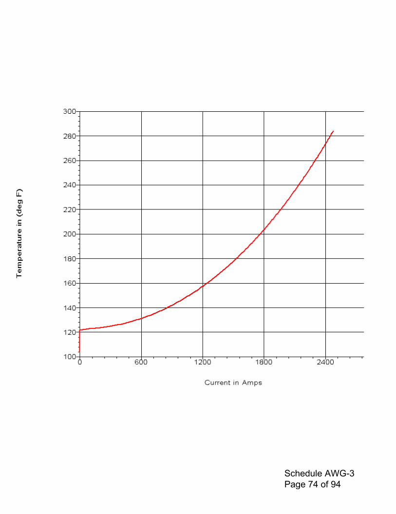
Schedule AWG-3 Page 74 of 94

Power Engineers Page 1/2
PLS-CADD Version 10.60x64 2:20:02 PM Wednesday, August 11, 2010Power Engineers
IEEE Std. 738-2006 method of calculation
Air temperature is 104.00 (deg F)=40 9deg C)Wind speed is 2.00 (ft/s)Angle between wind and conductor is 90 (deg)Conductor elevation above sea level is 1000 (ft)Conductor bearing is -7 (deg) (perpendicular to solar azimuth for maximum solar heating)Sun time is 14 hours (solar altitude is 63 deg. and solar azimuth is -97 deg.)Conductor latitude is 30.0 (deg)Atmosphere is CLEARDay of year is 172 (corresponds to June 21 in year 2010) (day of the year with most solar heating)
Conductor description: 1272 kcmil 45/7 Strands BITTERN ACSR - Adapted from 1970's PubliclyAvailable DataConductor diameter is 1.345 (in)Conductor dc resistance is 0.0714 (Ohm/mile) at 68.0 (deg F) and 0.0863 (Ohm/mile) at 167.0 (deg F)Emissivity is 0.5 and solar absorptivity is 0.5
Solar heat input is 5.424 (Watt/ft) (corresponds to Global Solar Radiation of 96.778 (Watt/ft^2) - which was calculated)Radiation cooling is 18.109 (Watt/ft)Convective cooling is 45.141 (Watt/ft)
Given a constant ac current of 1714.0 amperes,The conductor temperature is 284.1 (deg F)=140 (deg C)
Schedule AWG-3 Page 75 of 94
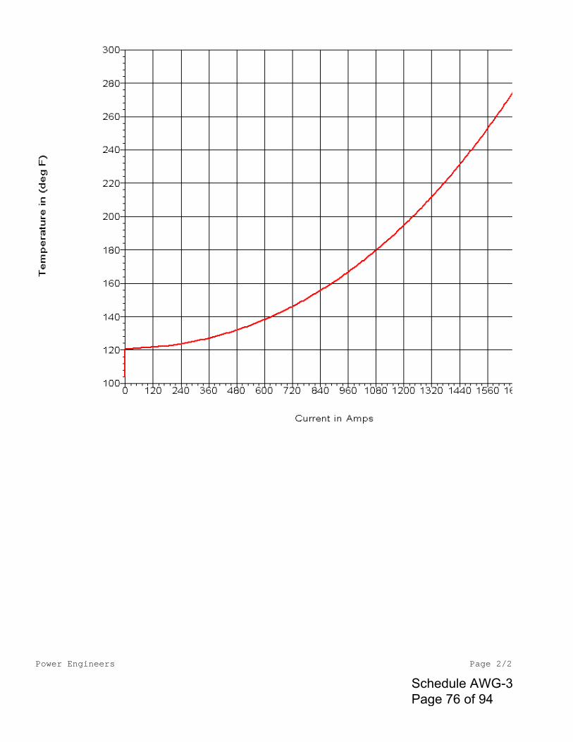
Power Engineers Page 2/2
Schedule AWG-3 Page 76 of 94
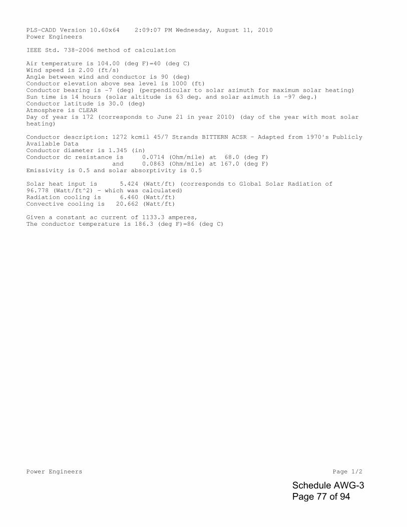
Power Engineers Page 1/2
PLS-CADD Version 10.60x64 2:09:07 PM Wednesday, August 11, 2010Power Engineers
IEEE Std. 738-2006 method of calculation
Air temperature is 104.00 (deg F)=40 (deg C)Wind speed is 2.00 (ft/s)Angle between wind and conductor is 90 (deg)Conductor elevation above sea level is 1000 (ft)Conductor bearing is -7 (deg) (perpendicular to solar azimuth for maximum solar heating)Sun time is 14 hours (solar altitude is 63 deg. and solar azimuth is -97 deg.)Conductor latitude is 30.0 (deg)Atmosphere is CLEARDay of year is 172 (corresponds to June 21 in year 2010) (day of the year with most solar heating)
Conductor description: 1272 kcmil 45/7 Strands BITTERN ACSR - Adapted from 1970's PubliclyAvailable DataConductor diameter is 1.345 (in)Conductor dc resistance is 0.0714 (Ohm/mile) at 68.0 (deg F) and 0.0863 (Ohm/mile) at 167.0 (deg F)Emissivity is 0.5 and solar absorptivity is 0.5
Solar heat input is 5.424 (Watt/ft) (corresponds to Global Solar Radiation of 96.778 (Watt/ft^2) - which was calculated)Radiation cooling is 6.460 (Watt/ft)Convective cooling is 20.662 (Watt/ft)
Given a constant ac current of 1133.3 amperes,The conductor temperature is 186.3 (deg F)=86 (deg C)
Schedule AWG-3 Page 77 of 94
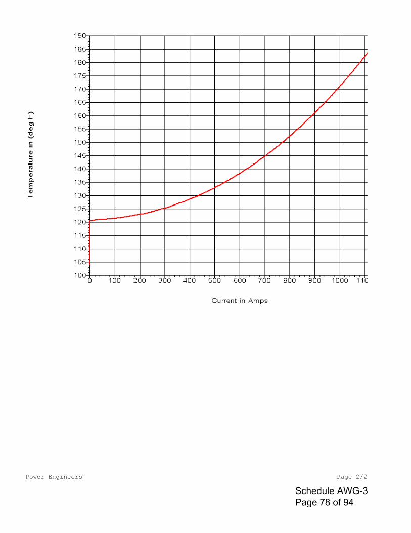
Power Engineers Page 2/2
Schedule AWG-3 Page 78 of 94

PLS-CADD Version 10.60x64 2:34:38 PM Tuesday, August 10, 2010 Power Engineers IEEE Std. 738-2006 method of calculation Air temperature is 104.00 (deg F)=40 (deg C) Wind speed is 2.00 (ft/s) Angle between wind and conductor is 90 (deg) Conductor elevation above sea level is 1000 (ft) Conductor bearing is -7 (deg) (perpendicular to solar azimuth for maximum solar heating) Sun time is 14 hours (solar altitude is 63 deg. and solar azimuth is -97 deg.) Conductor latitude is 30.0 (deg) Atmosphere is CLEAR Day of year is 172 (corresponds to June 21 in year 2010) (day of the year with most solar heating) Conductor description: 2156 kcmil 84/19 Strands BLUEBIRD ACSR - Adapted from 1970's Publicly Available Data Conductor diameter is 1.762 (in) Conductor resistance is 0.0423 (Ohm/mile) at 68.0 (deg F) and 0.0499 (Ohm/mile) at 167.0 (deg F) Emissivity is 0.5 and solar absorptivity is 0.5 Solar heat input is 7.105 (Watt/ft) (corresponds to Global Solar Radiation of 96.778 (Watt/ft^2) - which was calculated) Radiation cooling is 4.685 (Watt/ft) Convective cooling is 14.307 (Watt/ft) Given a constant ac current of 1133.3 amperes, The conductor temperature is 153.6 (deg F)=68 (deg C)
Schedule AWG-3 Page 79 of 94
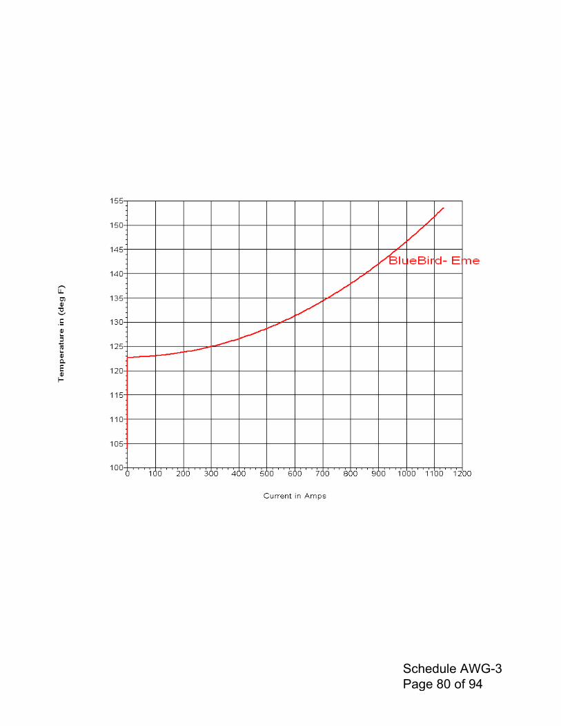
Schedule AWG-3 Page 80 of 94
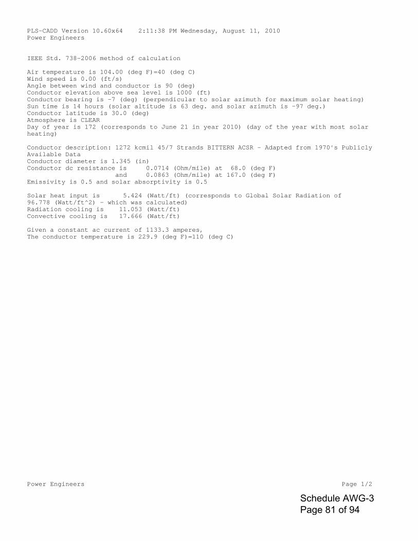
Power Engineers Page 1/2
PLS-CADD Version 10.60x64 2:11:38 PM Wednesday, August 11, 2010Power Engineers
IEEE Std. 738-2006 method of calculation
Air temperature is 104.00 (deg F)=40 (deg C)Wind speed is 0.00 (ft/s)Angle between wind and conductor is 90 (deg)Conductor elevation above sea level is 1000 (ft)Conductor bearing is -7 (deg) (perpendicular to solar azimuth for maximum solar heating)Sun time is 14 hours (solar altitude is 63 deg. and solar azimuth is -97 deg.)Conductor latitude is 30.0 (deg)Atmosphere is CLEARDay of year is 172 (corresponds to June 21 in year 2010) (day of the year with most solar heating)
Conductor description: 1272 kcmil 45/7 Strands BITTERN ACSR - Adapted from 1970's PubliclyAvailable DataConductor diameter is 1.345 (in)Conductor dc resistance is 0.0714 (Ohm/mile) at 68.0 (deg F) and 0.0863 (Ohm/mile) at 167.0 (deg F)Emissivity is 0.5 and solar absorptivity is 0.5
Solar heat input is 5.424 (Watt/ft) (corresponds to Global Solar Radiation of 96.778 (Watt/ft^2) - which was calculated)Radiation cooling is 11.053 (Watt/ft)Convective cooling is 17.666 (Watt/ft)
Given a constant ac current of 1133.3 amperes,The conductor temperature is 229.9 (deg F)=110 (deg C)
Schedule AWG-3 Page 81 of 94
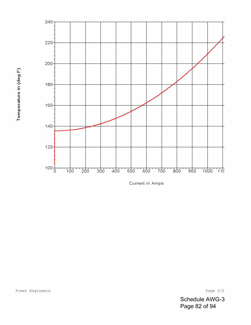
Power Engineers Page 2/2
Schedule AWG-3 Page 82 of 94

PLS-CADD Version 10.60x64 2:35:36 PM Tuesday, August 10, 2010 Power Engineers IEEE Std. 738-2006 method of calculation Air temperature is 104.00 (deg F)=40 (deg C) Wind speed is 0.00 (ft/s) Angle between wind and conductor is 90 (deg) Conductor elevation above sea level is 1000 (ft) Conductor bearing is -7 (deg) (perpendicular to solar azimuth for maximum solar heating) Sun time is 14 hours (solar altitude is 63 deg. and solar azimuth is -97 deg.) Conductor latitude is 30.0 (deg) Atmosphere is CLEAR Day of year is 172 (corresponds to June 21 in year 2010) (day of the year with most solar heating) Conductor description: 2156 kcmil 84/19 Strands BLUEBIRD ACSR - Adapted from 1970's Publicly Available Data Conductor diameter is 1.762 (in) Conductor resistance is 0.0423 (Ohm/mile) at 68.0 (deg F) and 0.0499 (Ohm/mile) at 167.0 (deg F) Emissivity is 0.5 and solar absorptivity is 0.5 Solar heat input is 7.105 (Watt/ft) (corresponds to Global Solar Radiation of 96.778 (Watt/ft^2) - which was calculated) Radiation cooling is 7.711 (Watt/ft) Convective cooling is 11.779 (Watt/ft) Given a constant ac current of 1133.3 amperes, The conductor temperature is 180.2 (deg F)=82 (deg C)
Schedule AWG-3 Page 83 of 94
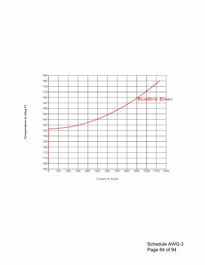
Schedule AWG-3 Page 84 of 94

8/11/2010
Power engineers
ACSR Bittern @ MOT=175 F=79 C for Normal Regime, Ampacity=1033.3 A Ruling Span=1500 ft Max Sag @ MOT=175 F=79 C, Final=64.08 ft
Conductor: 1272.0 Kcmil 45/ 7 Stranding ACSR "BITTERN"
Area = 1.0680 Sq. in Diameter = 1.345 in Weight = 1.434 lb/ft RTS = 34100 lb Data from Chart No. 1-957 English Units Limits and Outputs in Average Tensions.
Span = 1500.0 Feet Special Load Zone Creep is NOT a Factor Rolled Rod
Design Points Final Initial Temp Ice Wind K Weight Sag Tension RTS Sag Tension RTS °F in psf lb/ft lb/ft Ft lb % Ft lb % 0.0 0.50 4.00 0.30 2.997 55.96 15146 44.4 49.65 17050 50.0* 15.0 1.25 4.10 0.00 5.623 64.08 24862 72.9 64.08 24862 72.9 32.0 0.50 0.00 0.00 2.581 56.99 12812 37.6 49.25 14803 43.4 60.0 0.00 24.30 0.00 3.078 60.49 14404 42.2 53.69 16206 47.5 -20.0 0.00 0.00 0.00 1.434 48.54 8343 24.5 37.53 10773 31.6 0.0 0.00 0.00 0.00 1.434 50.29 8056 23.6 39.21 10313 30.2 30.0 0.00 0.00 0.00 1.434 52.83 7672 22.5 41.75 9690 28.4 60.0 0.00 0.00 0.00 1.434 55.30 7333 21.5 44.27 9141 26.8 90.0 0.00 0.00 0.00 1.434 57.69 7033 20.6 46.77 8658 25.4 120.0 0.00 0.00 0.00 1.434 60.00 6765 19.8 49.22 8230 24.1 175.0 0.00 0.00 0.00 1.434 64.08 6340 18.6 53.58 7566 22.2 * Design Condition
Certain information such as the data, opinions or recommendations set forth herein or given by Southwire representatives, is intended as a general guide only. Each installation of overhead electrical conductor, underground electrical conductor, and/or conductor accessories involves special conditions creating problems that require individual solutions and, therefore, the recipient of this information has the sole responsibility in connection with the use of the information. Southwire does not assume any liability in connection with such information.�
Schedule AWG-3 Page 85 of 94
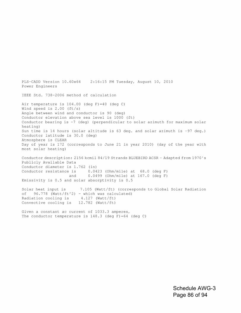
PLS-CADD Version 10.60x64 2:16:15 PM Tuesday, August 10, 2010 Power Engineers IEEE Std. 738-2006 method of calculation Air temperature is 104.00 (deg F)=40 (deg C) Wind speed is 2.00 (ft/s) Angle between wind and conductor is 90 (deg) Conductor elevation above sea level is 1000 (ft) Conductor bearing is -7 (deg) (perpendicular to solar azimuth for maximum solar heating) Sun time is 14 hours (solar altitude is 63 deg. and solar azimuth is -97 deg.) Conductor latitude is 30.0 (deg) Atmosphere is CLEAR Day of year is 172 (corresponds to June 21 in year 2010) (day of the year with most solar heating) Conductor description: 2156 kcmil 84/19 Strands BLUEBIRD ACSR - Adapted from 1970's Publicly Available Data Conductor diameter is 1.762 (in) Conductor resistance is 0.0423 (Ohm/mile) at 68.0 (deg F) and 0.0499 (Ohm/mile) at 167.0 (deg F) Emissivity is 0.5 and solar absorptivity is 0.5 Solar heat input is 7.105 (Watt/ft) (corresponds to Global Solar Radiation of 96.778 (Watt/ft^2) - which was calculated) Radiation cooling is 4.127 (Watt/ft) Convective cooling is 12.782 (Watt/ft) Given a constant ac current of 1033.3 amperes, The conductor temperature is 148.3 (deg F)=64 (deg C)
Schedule AWG-3 Page 86 of 94
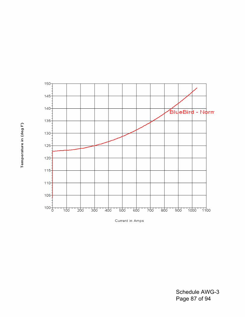
Schedule AWG-3 Page 87 of 94
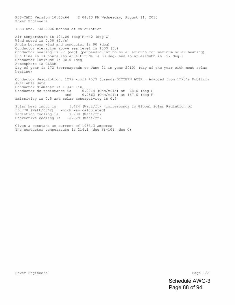
Power Engineers Page 1/2
PLS-CADD Version 10.60x64 2:04:13 PM Wednesday, August 11, 2010Power Engineers
IEEE Std. 738-2006 method of calculation
Air temperature is 104.00 (deg F)=40 (deg C)Wind speed is 0.00 (ft/s)Angle between wind and conductor is 90 (deg)Conductor elevation above sea level is 1000 (ft)Conductor bearing is -7 (deg) (perpendicular to solar azimuth for maximum solar heating)Sun time is 14 hours (solar altitude is 63 deg. and solar azimuth is -97 deg.)Conductor latitude is 30.0 (deg)Atmosphere is CLEARDay of year is 172 (corresponds to June 21 in year 2010) (day of the year with most solar heating)
Conductor description: 1272 kcmil 45/7 Strands BITTERN ACSR - Adapted from 1970's PubliclyAvailable DataConductor diameter is 1.345 (in)Conductor dc resistance is 0.0714 (Ohm/mile) at 68.0 (deg F) and 0.0863 (Ohm/mile) at 167.0 (deg F)Emissivity is 0.5 and solar absorptivity is 0.5
Solar heat input is 5.424 (Watt/ft) (corresponds to Global Solar Radiation of 96.778 (Watt/ft^2) - which was calculated)Radiation cooling is 9.280 (Watt/ft)Convective cooling is 15.029 (Watt/ft)
Given a constant ac current of 1033.3 amperes,The conductor temperature is 214.1 (deg F)=101 (deg C)
Schedule AWG-3 Page 88 of 94
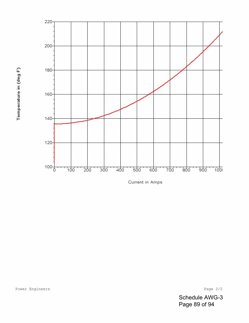
Power Engineers Page 2/2
Schedule AWG-3 Page 89 of 94

PLS-CADD Version 10.60x64 2:36:38 PM Tuesday, August 10, 2010 Power Engineers IEEE Std. 738-2006 method of calculation Air temperature is 104.00 (deg F)=40 (deg C) Wind speed is 0.00 (ft/s) Angle between wind and conductor is 90 (deg) Conductor elevation above sea level is 1000 (ft) Conductor bearing is -7 (deg) (perpendicular to solar azimuth for maximum solar heating) Sun time is 14 hours (solar altitude is 63 deg. and solar azimuth is -97 deg.) Conductor latitude is 30.0 (deg) Atmosphere is CLEAR Day of year is 172 (corresponds to June 21 in year 2010) (day of the year with most solar heating) Conductor description: 2156 kcmil 84/19 Strands BLUEBIRD ACSR - Adapted from 1970's Publicly Available Data Conductor diameter is 1.762 (in) Conductor resistance is 0.0423 (Ohm/mile) at 68.0 (deg F) and 0.0499 (Ohm/mile) at 167.0 (deg F) Emissivity is 0.5 and solar absorptivity is 0.5 Solar heat input is 7.105 (Watt/ft) (corresponds to Global Solar Radiation of 96.778 (Watt/ft^2) - which was calculated) Radiation cooling is 6.853 (Watt/ft) Convective cooling is 10.437 (Watt/ft) Given a constant ac current of 1033.3 amperes, The conductor temperature is 173.0 (deg F)=78 (deg C)
Schedule AWG-3 Page 90 of 94
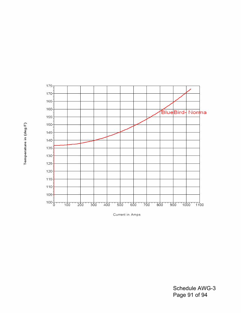
Schedule AWG-3 Page 91 of 94
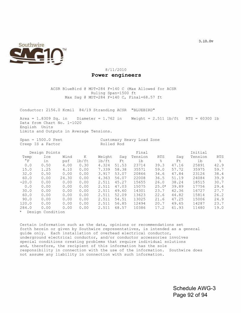
8/11/2010
Power engineers
ACSR BlueBird @ MOT=284 F=140 C (Max Allowed for ACSR Ruling Span=1500 ft Max Sag @ MOT=284 F=140 C, Final=68.57 ft
Conductor: 2156.0 Kcmil 84/19 Stranding ACSR "BLUEBIRD"
Area = 1.8309 Sq. in Diameter = 1.762 in Weight = 2.511 lb/ft RTS = 60300 lb Data from Chart No. 1-1020 English Units Limits and Outputs in Average Tensions.
Span = 1500.0 Feet Customary Heavy Load Zone Creep IS a Factor Rolled Rod
Design Points Final Initial Temp Ice Wind K Weight Sag Tension RTS Sag Tension RTS °F in psf lb/ft lb/ft Ft lb % Ft lb % 0.0 0.50 4.00 0.30 4.324 51.53 23714 39.3 47.16 25891 42.9 15.0 1.25 4.10 0.00 7.339 58.38 35571 59.0 57.72 35975 59.7 32.0 0.50 0.00 0.00 3.917 53.07 20866 34.6 47.84 23126 38.4 60.0 0.00 24.30 0.00 4.363 56.07 22008 36.5 51.19 24084 39.9 -20.0 0.00 0.00 0.00 2.511 45.27 15655 26.0 38.24 18515 30.7 0.0 0.00 0.00 0.00 2.511 47.03 15075 25.0* 39.89 17756 29.4 30.0 0.00 0.00 0.00 2.511 49.60 14301 23.7 42.36 16727 27.7 60.0 0.00 0.00 0.00 2.511 52.09 13623 22.6 44.82 15814 26.2 90.0 0.00 0.00 0.00 2.511 54.51 13025 21.6 47.25 15006 24.9 120.0 0.00 0.00 0.00 2.511 56.85 12494 20.7 49.65 14287 23.7 284.0 0.00 0.00 0.00 2.511 68.57 10386 17.2 61.93 11480 19.0 * Design Condition
Certain information such as the data, opinions or recommendations set forth herein or given by Southwire representatives, is intended as a general guide only. Each installation of overhead electrical conductor, underground electrical conductor, and/or conductor accessories involves special conditions creating problems that require individual solutions and, therefore, the recipient of this information has the sole responsibility in connection with the use of the information. Southwire does not assume any liability in connection with such information.�
Schedule AWG-3 Page 92 of 94
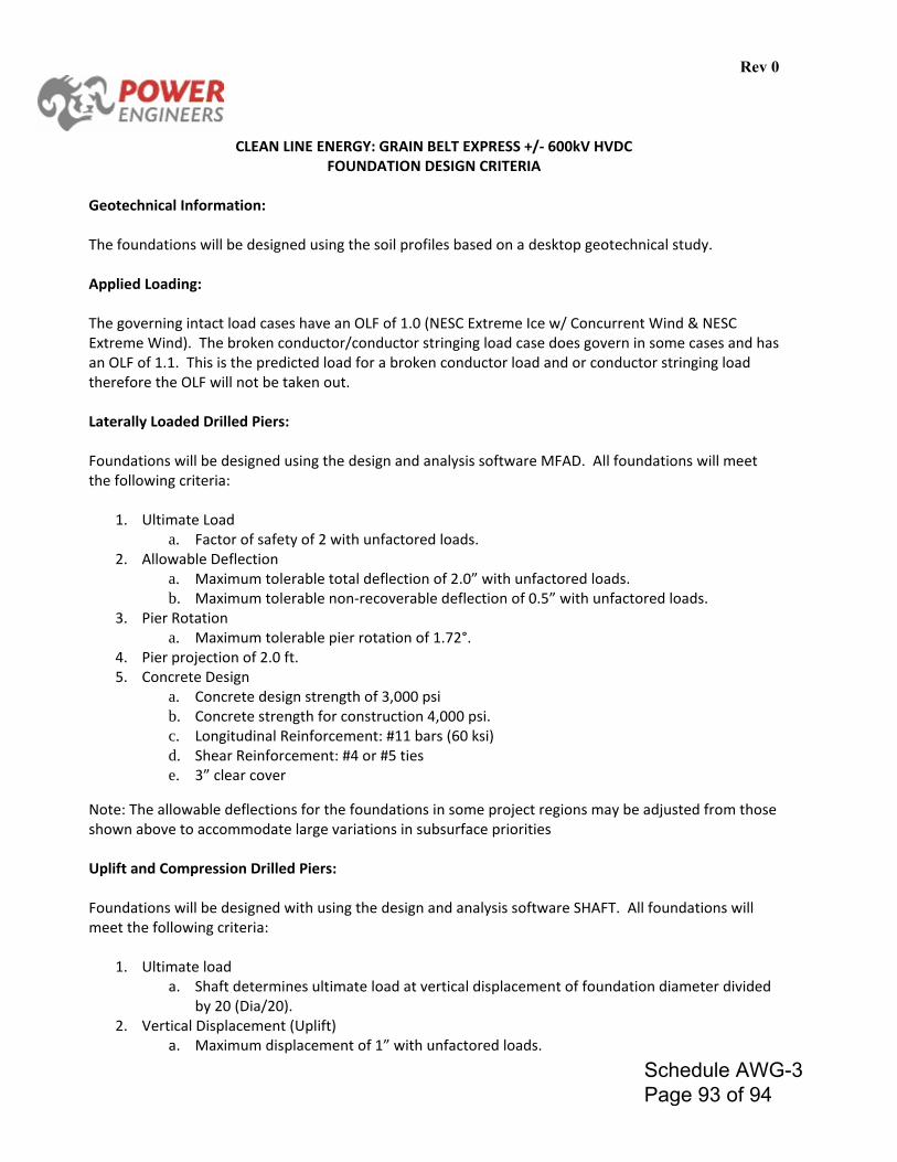
Rev 0
CLEAN LINE ENERGY: GRAIN BELT EXPRESS +/- 600kV HVDC
FOUNDATION DESIGN CRITERIA Geotechnical Information: The foundations will be designed using the soil profiles based on a desktop geotechnical study. Applied Loading: The governing intact load cases have an OLF of 1.0 (NESC Extreme Ice w/ Concurrent Wind & NESC Extreme Wind). The broken conductor/conductor stringing load case does govern in some cases and has an OLF of 1.1. This is the predicted load for a broken conductor load and or conductor stringing load therefore the OLF will not be taken out. Laterally Loaded Drilled Piers: Foundations will be designed using the design and analysis software MFAD. All foundations will meet the following criteria:
1. Ultimate Load a. Factor of safety of 2 with unfactored loads.
2. Allowable Deflection a. Maximum tolerable total deflection of 2.0” with unfactored loads. b. Maximum tolerable non-recoverable deflection of 0.5” with unfactored loads.
3. Pier Rotation a. Maximum tolerable pier rotation of 1.72°.
4. Pier projection of 2.0 ft. 5. Concrete Design
a. Concrete design strength of 3,000 psi b. Concrete strength for construction 4,000 psi. c. Longitudinal Reinforcement: #11 bars (60 ksi) d. Shear Reinforcement: #4 or #5 ties e. 3” clear cover
Note: The allowable deflections for the foundations in some project regions may be adjusted from those shown above to accommodate large variations in subsurface priorities Uplift and Compression Drilled Piers: Foundations will be designed with using the design and analysis software SHAFT. All foundations will meet the following criteria:
1. Ultimate load a. Shaft determines ultimate load at vertical displacement of foundation diameter divided
by 20 (Dia/20). 2. Vertical Displacement (Uplift)
a. Maximum displacement of 1” with unfactored loads.
Schedule AWG-3 Page 93 of 94
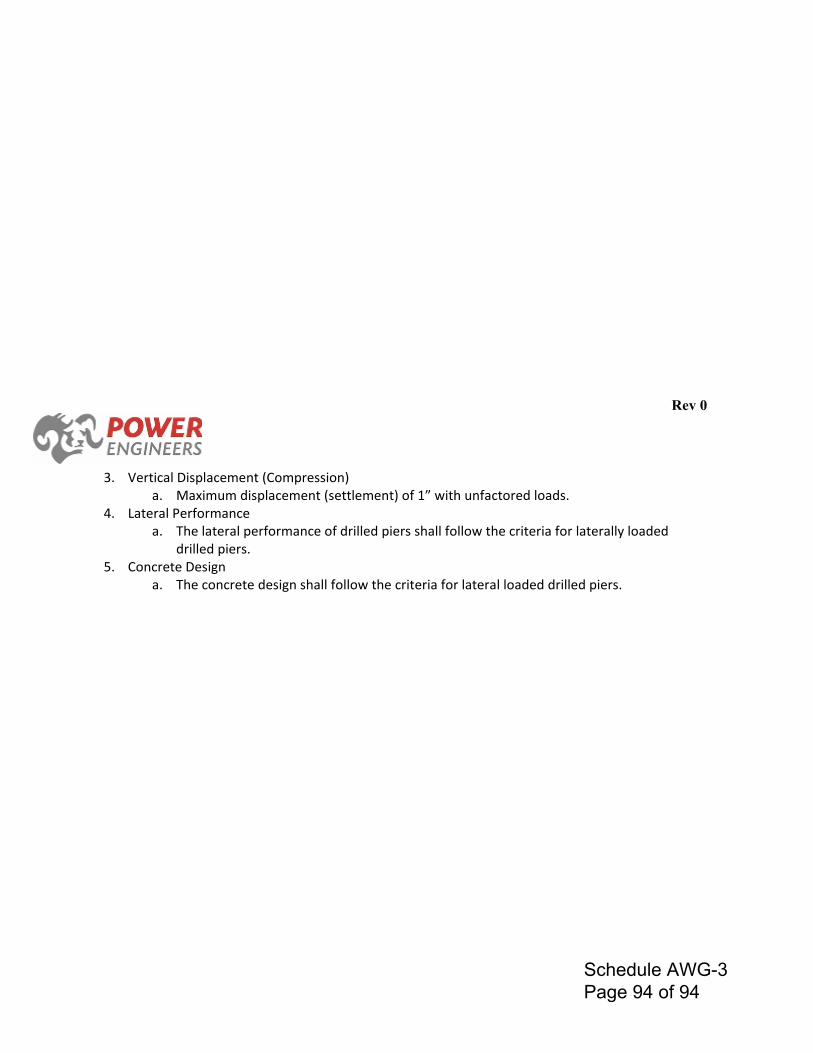
Rev 0
3. Vertical Displacement (Compression)
a. Maximum displacement (settlement) of 1” with unfactored loads. 4. Lateral Performance
a. The lateral performance of drilled piers shall follow the criteria for laterally loaded drilled piers.
5. Concrete Design a. The concrete design shall follow the criteria for lateral loaded drilled piers.
Schedule AWG-3 Page 94 of 94