Embed Size (px)
Citation preview
Field GeologY
Unit III
Unit III :SYLLABUS
Field Equipments -Clinometer compass: different parts and their functions.
Measuring attitude of linear structures – determination of bearings – advantages
and limitations. Brunton Compass: different parts and their functions measuring
attitude and trends – determination of bearings – adjustments – magnetic
declination in topographic sheets -advantages and limitations. Brief account on
the utility of Prismatic Compass and Plane Table in mapping open cast mines and
quarries. Field equpiments
Clinometer
Parts and its function
A compass is an instrument used for navigation and orientation that shows
direction relative to the geographic cardinal directions, or "points".
An inclinometer or clinometer is an instrument for measuring angles of slope
(or tilt), elevation or depression of an object with respect to gravity. It is also
known as a tilt meter, tilt indicator, slope alert, slope gauge, gradient meter,
gradiometer, level gauge, level meter, declinometer, and pitch & roll indicator.
Clinometers measure both inclines (positive slopes, as seen by an observer
looking upwards) and declines (negative slopes, as seen by an observer looking
downward) using three different units of measure: degrees, percent, and topo.
An inclinometer or clinometer is an instrument used for measuring angles
of slope (or tilt), elevation, or depression of an object with respect to gravity's
direction. It is also known as a tilt indicator, tilt sensor, tilt meter, slope
alert, slope gauge, gradient meter, gradiometer, level gauge, level
meter, declinometer, and pitch & roll indicator. Clinometers measure both
inclines (positive slopes, as seen by an observer looking upwards) and declines
(negative slopes, as seen by an observer looking downward) using three different
units of measure: degrees, percent, and topo (see Grade (slope) for
details). Astrolabes are inclinometers that were used for navigation and locating
astronomical objects from ancient times to the Renaissance.
A tilt sensor can measure the tilting in often two axes of a reference plane in two
axes. In contrast, a full motion would use at least three axes and often additional
sensors. One way to measure tilt angle with reference to the earth's ground plane,
is to use an accelerometer. Typical applications can be found in the industry and
in game controllers. In aircraft, the "ball" in turn coordinators or turn and bank
indicators is sometimes referred to as an inclinometer.
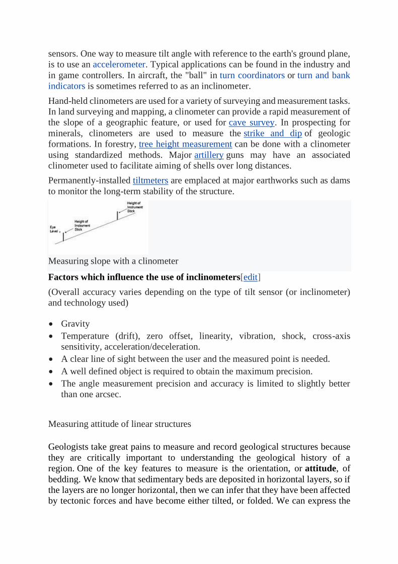
Hand-held clinometers are used for a variety of surveying and measurement tasks.
In land surveying and mapping, a clinometer can provide a rapid measurement of
the slope of a geographic feature, or used for cave survey. In prospecting for
minerals, clinometers are used to measure the strike and dip of geologic
formations. In forestry, tree height measurement can be done with a clinometer
using standardized methods. Major artillery guns may have an associated
clinometer used to facilitate aiming of shells over long distances.
Permanently-installed tiltmeters are emplaced at major earthworks such as dams
to monitor the long-term stability of the structure.
Measuring slope with a clinometer
Factors which influence the use of inclinometers[edit]
(Overall accuracy varies depending on the type of tilt sensor (or inclinometer)
and technology used)
• Gravity
• Temperature (drift), zero offset, linearity, vibration, shock, cross-axis
sensitivity, acceleration/deceleration.
• A clear line of sight between the user and the measured point is needed.
• A well defined object is required to obtain the maximum precision.
• The angle measurement precision and accuracy is limited to slightly better
than one arcsec.
Measuring attitude of linear structures
Geologists take great pains to measure and record geological structures because
they are critically important to understanding the geological history of a
region. One of the key features to measure is the orientation, or attitude, of
bedding. We know that sedimentary beds are deposited in horizontal layers, so if
the layers are no longer horizontal, then we can infer that they have been affected
by tectonic forces and have become either tilted, or folded. We can express the
orientation of a bed (or any other planar feature) with two values: first, the
compass orientation of a horizontal line on the surface—the strike—and second,
the angle at which the surface dips from the horizontal, (perpendicular to the
strike)—the dip (Figure 12.18).
It may help to imagine a vertical surface, such as a wall in your house. The strike
is the compass orientation of the wall and the dip is 90˚ from horizontal. If you
could push the wall so it’s leaning over, but still attached to the floor, the strike
direction would be the same, but the dip angle would be less than 90˚. If you
pushed the wall over completely so it was lying on the floor, it would no longer
have a strike direction and its dip would be 0˚. When describing the dip it is
important to include the direction. In other words. if the strike is 0˚ (i.e., north)
and the dip is 30˚, it would be necessary to say “to the west” or “to the
east.” Similarly if the strike is 45˚ (i.e., northeast) and the dip is 60˚, it would be
necessary to say “to the northwest” or “to the southeast.”
Measurement of geological features is done with a special compass that has a
built-in clinometer, which is a device for measuring vertical angles. An example
of how this is done is shown on Figure 12.19.
Strike and dip are also used to describe any other planar features, including joints,
faults, dykes, sills, and even the foliation planes in metamorphic rocks.
Clinometer compass advantage and limitataion
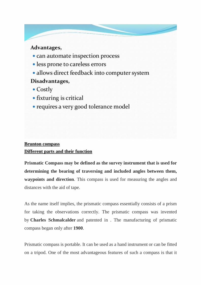
Brunton compass
Different parts and their function
Prismatic Compass may be defined as the survey instrument that is used for
determining the bearing of traversing and included angles between them,
waypoints and direction. This compass is used for measuring the angles and
distances with the aid of tape.
As the name itself implies, the prismatic compass essentially consists of a prism
for taking the observations correctly. The prismatic compass was invented
by Charles Schmalcalder and patented in . The manufacturing of prismatic
compass began only after 1900.
Prismatic compass is portable. It can be used as a hand instrument or can be fitted
on a tripod. One of the most advantageous features of such a compass is that it
facilitates both sighting and reading simultaneously. Due to this reason, it is
extensively used in land surveying.
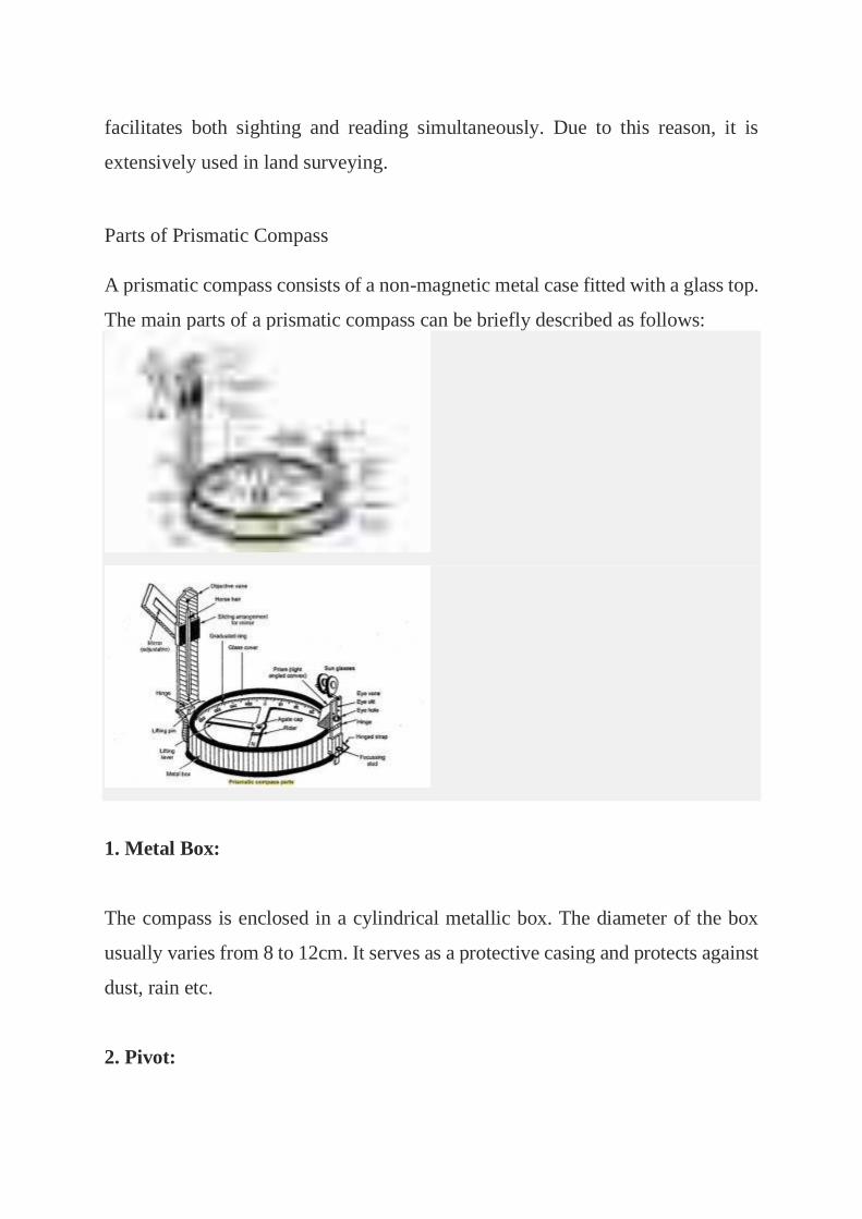
Parts of Prismatic Compass
A prismatic compass consists of a non-magnetic metal case fitted with a glass top.
The main parts of a prismatic compass can be briefly described as follows:
1. Metal Box:
The compass is enclosed in a cylindrical metallic box. The diameter of the box
usually varies from 8 to 12cm. It serves as a protective casing and protects against
dust, rain etc.
2. Pivot:
Pivot is the centrally located part that provides support to the freely suspended
magnetic needle.
3. Lifting Pin and Lifting Lever:
Lifting pin is provided right below the sight vane. The lifting pin gets pressed as
the sight vane is folded. The arrangement of lifting pin and lever help to lift the
magnetic needle from the pivot point. This prevents the damage to the pivot head.
4. Magnetic Needle:
The magnetic needle is the main part of a prismatic compass. It measures the angle
of a line from the magnetic meridian as the needle always points towards north
and south pole at the two ends of the needle when freely suspended. It is regarded
as the heart of a prismatic compass.
5. Ring or Graduated Circle:
The graduated circle consists of an aluminium ring that measures the bearing. It is
marked from 0 degrees to 360 degrees and is attached to the magnetic needle.
6. Prism:
Prism is used to take the exact readings and is placed exactly opposite to the object
vane. The hole of the prism is protected from dust and rain by a prism cap.
7. Object Vane:
The object vane is placed diametrically opposite to the prism and eye vane. The
main purpose of object vane is to sight the object in line with the eyesight. It
consists of horsehair or black wire.
8. Eye Vane:
Eye vane is a fine silt-like part provided to bisect the object from silt. It consists
of an eye-hole at the bottom.
9. Glass Cover:
The glass cover is provided to cover the instrument box. A provided glass cover
protects the instrument and is transparent which helps in taking the readings.
10. Sunglasses:
Sunglasses can be used when a luminous object has to be bisected.
11. Reflecting Mirror:
Reflecting mirror is directly placed on the object vane. It is used to get the image
of an object located below or above the instrument level.
12 Spring Break:
It is also known as the break pin. Spring Break is provided on the compass to damp
the oscillation before a reading is taken.
Determination of bearing
The major parts of the Brunton compass are shown in Figure 4.1. The compass
itself is made up of brass and aluminium – these being materials that will not
affect the magnetized compass needle. Objectives At the end of this lecture you
should be able to: (a). Describe and illustrate the various parts of the Brunton
compass. (b). Outline the procedure of taking bearings with the compass (c).
Distinguish Dip and Strike attitude measurements. (d) Determine suitable
parameters for measurement of dip and strike attitudes in the field. (d) Measure
the trend and plunge of linear features (e) Describe the safety procedures and
maintenance of the compass and clinometer. Lecture Series SGL 308:
Introduction to Geological Mapping Lecture 4 44 Fig. 4.1. The Brunton Compass.
Inset at lower left shows enlarged section through needle bearing. When the
compass is open, the compass needle rests on the pivot needle (see Fig. 4.1). The
compass needle can be braked to a stop by pushing the lift pin, which is located
near the rim of the box. When the compass box is closed, the lift pin protects the
pivot needle from wear by lifting up the compass needle. The round bull’s eye
bubble is used to level the compass when a bearing is read, and the tube bubble
is used to take readings with the clinometer. The clinometer is moved by a small
lever on the under-side of the compass box (not shown in the Figure). A compass
should be checked to ascertain that: 1. Both levels have bubbles 2. The hinges are
tight enough so that the lid, sighting arm, and the peep sights do not fold down
under their own weight, and 3. The point of the sighting arm meets the black axial
line of the mirror when the mirror and sighting are turned together until they
touch. Describe and illustrate the various parts of the Brunton compass.
TAKING BEARINGS WITH THE COMPASS
What is a bearing? A bearing is the compass direction from one point to another.
A bearing always has a unidirectional sense; for example, if the bearing from A
to B is N 30 W, the bearing from B to A can only be S 30 E. Using the Brunton
compass, the correct bearing sense is from the compass to the point sighted when
the sighting arm is aimed at the point. The white end of the needle gives the
bearing directly because the E and W markings are transposed.
To read accurate bearings, three things must be done simultaneously: • The
compass must be levelled • The point sighted must be centered exactly in the
sights, and • The needle must be brought nearly to rest.
Procedure of Taking a Bearing
a). When the Point sighted is from the Level of the waist or chest When the point
sighted is visible from the level of the waist or chest,
1. Open the lid about 135o ; turn the sighting arm out and turn up its hinged point
(Fig.4.2A). 2. Standing with the feet somewhat apart, hold the compass at waist
height with the box cupped in the left hand.
3. Center the bull’s eye bubble, and, keeping it approximately centered, adjust
the mirror with the right hand until the point sighted and the end of the sighting
arm appear in it.
4. Holding the compass exactly level, rotate the whole compass (on an imaginary
vertical axis) until the mirror images of the point sighted and the tip of the sighting
arm are superimposed on the black axial line of the mirror.
5. Read the bearing indicated by the white end of the needle, which should be
nearly at rest. 6. After reading the bearing, check to make sure the line of sight is
correct and the compass is level. 7. Record or plot the bearing at once.
b). When the Point sighted is from the eye level or on a steep downhill sight.
When the point sighted is visible only at eye level (see Fig. 4.2 B) or by a steep
downhill sight, the following instructions should apply.
1. Fold out the sighting arm as above, but open the lid only about 45o (Fig. 4.2B).
Take a walk to an open field and attempt to take the bearing of two objects that
can be sighted at the waist or chest level. Lecture Series SGL 308: Introduction
to Geological Mapping Lecture 4 47
2. Hold the compass in the left hand at eye level, with the sighting arm pointing
toward, and about 1ft from, the right eye.
3. Level the compass approximately by observing the mirror image of the bull’s
eye bubble, and, holding the compass approximately level, rotate it until the point
sighted appears in the small sighting window of the lid.
4. Holding the compass exactly level, rotate it until the point sighted and the
point of the sighting arm coincide with the axial line of the window.
5. Read the bearing mirror, double checking for alignment and level.
6. Transpose the direction of the bearing before recording or plotting it (the
compass was pointed in reverse of its bearing direction)
. USING THE BRUNTON COMPASS AS A HAND LEVEL
The Brunton compass is converted to a hand level by setting the clinometer
exactly at 0, opening the lid 45o , and extending the sighting arm with the sighting
point turned up. The compass is held in the same way as when measuring vertical
angles. It is tilted slowly until the mirror image of the tube bubble is centered.
Any point lined up with the tip of the sighting arm and the axial line of the
sighting window is now at the same elevation as the eye of the observer. By
carefully rotating the entire instrument with a horizontal motion, a series of points
that are at the same elevation can be noted. Take a walk to a hilly terrain and
attempt to take the bearing of two objects that can be sighted at the eye level or
on a steep downhill.
DIP AND STRIKE
In this section, we shall try to understand the significance of Dip and Strike. Dip
and strike are two important attitude parameters to be deduced in the field for any
inclined or layered strata.
Dip
Dip is essentially an angle of inclination of the bed. It is defined as the amount
of inclination of a bed with respect to an horizontal plane. This is measured on a
vertical plane lying at right angles to the strike of the bedding
Types of Dip
There are two types of Dips, namely: (i). True Dip and (ii).
Apparent Dip (i). True Dip – It is the maximum amount of slope along a line
perpendicular to the strike, in other words, it is the maximum slope with respect
to the horizontal. It may also be stated as the geographical direction along which
the line of quickest descent slopes down. (ii). Apparent Dip – Along any direction
other than that of the true dip, the gradient is scheduled to be much less and
therefore it is defined as the apparent dip. The apparent dip of any bed towards
any direction must always be less than its true dip.
Strike
The direction of the line along which an inclined bed intersects a horizontal plane
is known as the strike of the bed. It is a scalar quantity, as it has only one
component, i.e., direction but not magnitude. The strike of the bed is independent
of its amount of dip.
Importance of Dip and Strike
In structural geology, Strike and Dip are quite important for the following
purposes:
(a). To determine the younger bed of formation. It is well known that younger
beds will always be found in the direction of Dip. If we go in the direction of dip,
relatively beds of younger age will be found to out-crop and older rocks in the
opposite direction. (b). In the classification, and nomenclature of folds, faults,
joints and unconformities, the nature of dip and strike is of paramount
significance. Thus the attitude, which refers to the three dimensional orientation
of some geological structures, is defined by their dip and strike.
MEASURING STRIKE AND DIP
The strike and dip of planar geologic structures, such as bedding, faults, joints
and foliations, can be determined by several methods with the Brunton compass.
Strike is generally defined as the line of intersection between a horizontal plane
and the planar surface being measured. It is found by measuring the compass
direction of a horizontal line on the surface. Dip is the slope of the surface at right
angles to the line (see Fig. 4.3). The best method for measuring a given strike and
dip depends on the nature of the outcrop and the degree of accuracy desired. The
amount of the dip, too, may affect the choice because steeply dipping planar
structures can be measured far more accurately and easily than gently dipping
ones. Special methods are needed to measure dips of less than 5 o accurately. In
the section on taking bearings (Section 4.2.1), it was noted that a bearing has a
unidirectional sense and that the white ended of the compass needle must be read
in all
cases. It is recommended that for measuring strike only the north half of the
compass be used, regardless of which end of the needle points there. Strikes
would thereby be read as northeast or northwest, never southeast or southwest.
This helps eliminate the occasional serious error of transposing a strike to the
opposite quadrant when reading, plotting, or recording it. These errors can occur
easily where two men are working together and calling out structural data from
one to the other.
Where to Take Strike and Dip
Before measuring strike and dip, it must be determined whether the attitude will
reliably represent bedding. Some “outcrops” are not in place at all, being large
boulders, blocks of float, or segments of landslides. A general survey of the slopes
around outcrops will generally resolve such problems. If there is still some
question as to the reliability of a measurement, a question mark may be entered
next to the plotted symbol or the strike line may be broken. Outcrops should also
be examined to make certain that what is taken for bedding or foliation is not
jointing, bands of limonite staining, or some other kind of discoloration. Changes
in texture (especially grain-size) or changes in mineral composition are the best
indicators of bedding. In massive sandstones, bedding may be shown only by the
approximate planar orientation of mica flakes, platy carbonaceous or fossil
fragments, shale chips, or platy and elongate pebbles. The possibility that bedding
features in sandstones are only local cross-bedding
must be considered. The identification of bedding in metamorphic rocks may be
still more difficult, and there are a number of planar structures of igneous and
metamorphic rocks that should be identified carefully wherever they are
measured and plotted.
MEASURING TREND AND PLUNGE OF LINEAR FEATURES
Trend and plunge are used to define the attitudes of linear features. The trend of
a linear feature is the compass direction of the vertical plane that includes the
feature. If the feature is horizontal, only the compass direction is needed to define
its attitude. If it is not horizontal, the trend is taken as the direction in which the
feature points (plunges) downward. The plunge is the vertical angle between the
feature and a horizontal line. To measure the trend of a linear feature, the observer
stands, if possible, directly over a surface that is parallel to the linear feature (Fig.
4.4). This surface is sometimes described as “containing” the feature or as the
surface on which its maximum length is seen.
CARE AND ADJUSTMENT OF THE BRUNTON COMPASS
Care of the Brunton compass Remember that as a competent geologist, it is
important to take a good care of your Brunton compass or any other equipment if
you are to obtain reliable data in the field. The compass, for example, should
never be carried open in the hand while walking over rough or rocky ground. If
extra mirror or glass covers are included in the field gear, these can be replaced
in the field, but if the hinges are bent or the level vials broken, the instrument
must be sent to the manufacturer for repair
If the compass is used in the rain, or if it is accidentally dropped in water, it should
be opened and dried because the needle will not function properly when the
bearing is wet. The glass cover can be removed by forcing the point of a knife
blade under the spring washer that holds it in place. With the washer off, the glass
cover can be lifted from the box, and the needle taken off its bearing. The cone-
shaped pit of the jewel bearing should be cleaned and dried with a sharpened
toothpick and a bit of soft cloth or soft paper. The needle lift is then removed and
the inside of the compass dried and cleaned. It is safe to suggest that this opening
and cleaning of the compass should be done by a competent technician. More
details of the serving procedure is presented by Compton (1968). 4.8.2
Adjustment of the Brunton
Compass Before a new or a borrowed compass is used in the field, it should be
checked to make certain the clinometer level is correctly set. To do this, the
clinometer is set at 0, and the compass is placed on a smooth board that has been
leveled exactly with an alidade or a good carpenter’s level (a bull’s eye is not
sufficiently accurate for this). If the tube bubble does not come to centre, the
compass is opened as described above and the clinometer level vial moved
appropriately. Ordinarily, this can be done without loosening the clinometer set
screw. The new setting is checked by placing the compass on the board again,
and the procedure repeated until the bubble is centered exactly. In starting work
in a new field area, one may find that the dip of the earth’s magnetic field is so
great as to cause the compass needle to rub against the glass lid when the compass
is held level. To correct this, the glass cover is removed and the copper wire coil
on the needle moved one way or the other until the needle lies level
USE OF THE HAND LENS
Geologists often look at rocks with a small magnifier called a hand lens in order
to pick out fine details – the twinning on a plagioclase crystal in gabbro or the
shape of quartz grains in sandstone, for example. Most hand lenses consist of one
or several optical elements protected by a metal or plastic swing-out case. There
are 7X, 10X, 14X, and 20X magnifiers. Geologists usually carry a hand lens on
a cord around their necks to have it handy. When looking at a specimen through
a hand lens, first bring the lens close to your eye with one hand. Then with the
other hand move the sample towered the lens until it comes into focus. You
should tilt your head back a bit so that as much light as possible falls on the
sample. Natural sunlight is preferable to incandescent or fluorescent lighting.
Prismatic compass advantage and limitation
Prismatic compass is a portable magnetic compass which can be either used as a
hand instrument or can be fitted on a tripod. It contains a prism which is used for
accurate measurement of readings. The greatest advantage of this compass is both
sighting and reading can be done simultaneously without changing the position.
Two types of adjustments:
1. Temporary adjustment
2. Permanent adjustment
Temporary adjustments
• Centering: it is the process of fixing the compass exactly over the station.
Centering is usually done by adjusting the tripod legs. Also a plumb-bob is
used to judge the accurate centering of instruments over the station.
• Leveling: the instrument has to be leveled if it is used as in hand or
mounted over a tripod. If it is used as in hand, the graduated disc should
swing freely and appears to be completely level in reference to the top edge
of the case. If the tripod is used, they usually have a ball and socket
arrangement for leveling purpose.
• Focusing the prism: Prism can be slide up or down for focusing to make
the readings clear and readable.
Permanent adjustments are same as in the Surveyor’s compass.
Utility of Prismatic compass in mapping open cast mines and quarries
A prismatic compass is a navigation and surveying instrument which is
extensively used to find out the bearing of the traversing and included angles
between them, waypoints (an endpoint of the lcourse) and
direction.[1] Compass surveying is a type of surveying in which the directions of
surveying lines are determined with a magnetic compass, and the length of the
surveying lines are measured with a tape or chain or laser range finder.[2] The
compass is generally used to run a traverse line. The compass calculates bearings
of lines with respect to magnetic needle. The included angles can then be
calculated using suitable formulas in case of clockwise and anti-clockwise
traverse respectively. For each survey line in the traverse, surveyors take two
bearings that is fore bearing and back bearing which should exactly differ by
180° if local attraction is negligible. The name Prismatic compass is given to it
because it essentially consists of a prism which is used for taking observations
more accurately.
Compass surveying is the branch of surveying in which the position of an object
is located using angular measurements determined by a compass and linear
measurements using a chain or tape. Compass surveying is used in following
circumstances:
• If the surveying area is large, chain surveying is not adopted for surveying
rather compass surveying is employed.
• If the plot for surveying has numerous obstacles and undulations which
prevents chaining.
• If there is a time limit for surveying, compass surveying is usually adopted
• Compass surveying is not used in places which contain iron core, power lines
etc which usually attracts magnets due to their natural properties and
electromagnetic properties respectively. Compass surveying is done by using
traversing. A traverse is formed by connecting the points in the plot by means
of a series of straight line.
Utility of plane table in mapping open mines and quarries
1. Plane Table Surveying is a graphical method of survey in which the field
observations and plotting are done simultaneously. It is simple and
cheaper, It is most suitable for small scale maps. The plan is drawn by
the surveyor in the field, while the area to be surveyed is before his eyes.
Therefore, there is no possibility of omitting the necessary
measurements. 12
2. 13. Equipments and Accessories for Plane Tabling The following
instruments are used in plane table surveying. Equipments: Plane Table
Tripod Alidade Trough Compass Spirit level U-Fork with Plumb
bob Water proof cover Drawing paper Pins Drawing accessories 13
3. 14. Plane Table 14
4. 15. ALIDADE The alidade is useful for establishing a line of sight. Two
Types of alidade are used. Simple alidade Telescopic alidade 15
5. 16. SIMPLE ALIDADE 16
6. 17. TELESCOPIC ALIDADE 17
7. 18. TROUGH COMPASS 18
8. 19. SPIRIT LEVEL 19
9. 20. U-Fork With Plumb Bob 20
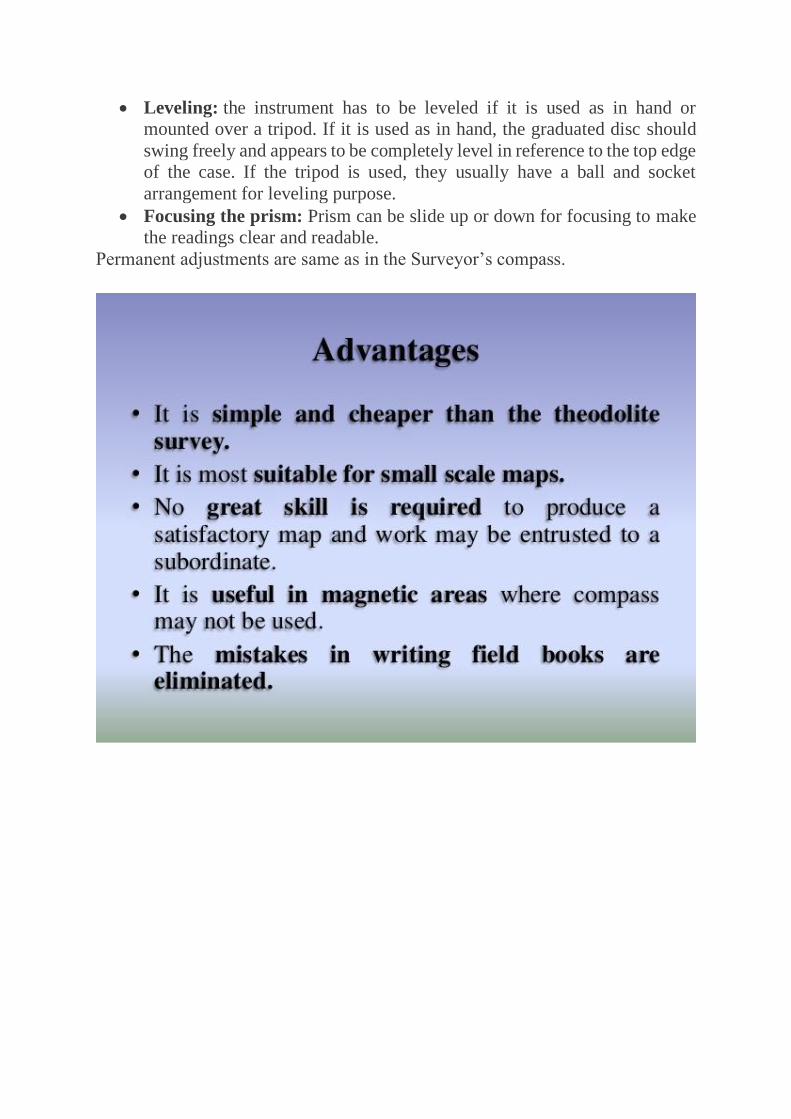
10. 21. ADVANTAGES AND DISADVANTAGES OF PLANE TABLE
SURVEYING 21
11. 22. Advantages It is simple and cheaper than the theodolite survey. It
is most suitable for small scale maps. No great skill is required to produce
a satisfactory map and work may be entrusted to a subordinate. It is useful
in magnetic areas where compass may not be used. The mistakes in
writing field books are eliminated. 22
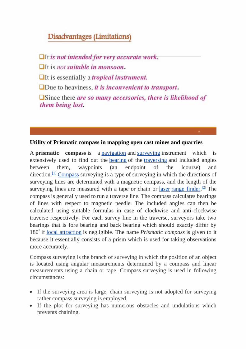
12. 23. Disadvantages (Limitations) It is not intended for very accurate work.
It is not suitable in monsoon. It is essentially a tropical instrument. Due
to heaviness, it is inconvenient to transport. Since there are so many
accessories, there is likelihood of them being lost. 23
13. 24. Methods Of Plane Tabling There are four distinct methods of plane
tabling: Method of Radiation Method of Intersection Method of
Traversing Method of Resection 24
14. 25. Radiation Method 25
15. 26. Method Of Intersection 26
16. 27. Method Of Traversing 27
17. 28. Method of Resection 28
18. 29. Two Point Problem In this problem, two well-defined points whose
positions have already been plotted on the plan are selected. Then, by
perfectly bisecting these points, a new station is established at the required
position. 29
19. 30. Two Point Problem 30
20. 31. The Three Point Problem In this problem, three well defined points are
selected, whose position have already been plotted on the map. Then, by
perfectly bisecting these three well-defined points. A new station is
established at the required position. No auxiliary station is required in order
to solve this problem. This table is directly placed at the required position.
The problem may be solved by following methods (a) Bessel’s method (b)
Mechanical Method (c) The trial and error method 31
A plane table (plain table prior to 1830)[1] is a device used in surveying and
related disciplines to provide a solid and level surface on which to make field
drawings, charts and maps. The early use of the name plain table reflected its
simplicity and plainness rather than its flatness.
BY
M.P.KOWSALYA
Referrences
• https ://www.britannica .com>science>altitude
• https ://www.files.ethz.ch>English>inclination
• https ://.osu.edu>handle
• https ://careeertrend.com>…>job description
• https ://www.vsatplus.coms products >
• https ://kb.osu.edu>handle.advantages.comp