Embed Size (px)
Citation preview
D(
NAa
b
c
a
ARRAA
KSIDSHD
1
ddtdcv
LppdldcialPc
0h
Electric Power Systems Research 108 (2014) 113– 123
Contents lists available at ScienceDirect
Electric Power Systems Research
jou rn al hom e page: www.elsev ier .com/ locate /epsr
irect power control of shunt active filter using high selectivity filterHSF) under distorted or unbalanced conditions
adhir Mesbahia, Ahmed Ouaria, Djaffar Ould Abdeslamb,∗, Tounsia Djamahc,mar Omeiri a
Department of Electrical Engineering, Faculty of Sciences Engineering, Badji Mokhtar-Annaba University, P.O. Box 12, 23000 Annaba, AlgeriaMIPS Laboratory, Mulhouse University, 4 rue des Frères Lumière, 68093 Mulhouse, FranceL2CSP Laboratory, Mouloud Mammeri University, Tizi-Ouzou, Algeria
r t i c l e i n f o
rticle history:eceived 29 April 2013eceived in revised form 14 October 2013ccepted 7 November 2013vailable online 30 November 2013
a b s t r a c t
This paper describes the design of a new configuration of direct power control (DPC) based on high selec-tivity filters (HSF) to achieve near-sinusoidal source current waveforms under different source voltageconditions. The proposed method uses the high selectivity filters instead of the classical extraction filters(low pass filters). The basic idea of the proposed DPC is to choose the best inverter voltage vector in orderto minimize instantaneous active and reactive power errors using two hysteresis comparators. Their out-puts associated with a switching table, control the active and reactive powers by selecting the optimal
eywords:hunt active power filter (SAPF)nstantaneous powersirect power control (DPC)witching table
switching states of the inverter. Simulation results have proved excellent performance, and verify thevalidity of the proposed DPC scheme, which is much better than conventional DPC using low pass filters.
© 2013 Elsevier B.V. All rights reserved.
igh selectivity filteristorted or unbalanced conditions
. Introduction
Nowadays, the widespread use of non-linear loads leads toegradation of power quality of the electrical distribution systemsue to generation of high harmonic currents. This results in mul-iple disagreements such as: increase of line losses, saturation ofistribution transformers, and interference to adjacent communi-ation systems. These effects can be worse in the case where theoltages and/or loads are unbalanced.
To improve the power quality, traditional solutions like passiveC filters have been widely used for a long time [1]. However, bulkassive components, series and parallel resonance and fixed com-ensation characteristics for fixed values of L and C are the mainrawbacks of passive LC filters. In order to overcome all these prob-
ems simultaneously, various active power filters (APFs) have beeneveloped in recent years [1,2] due to the development in poweronverters and digital signal processors. The objective of these APFss to reduce the voltage and current harmonic distortion [3]. Thective power filter topology can be connected in series or paral-
el and combinations of both (unified power quality conditioners).assive filters combined with active shunt and series are some typi-al (hybrid) configurations. Most of the industrial applications need∗ Corresponding author. Tel.: +33 389 336020; fax: +33 389 336084.E-mail address: [email protected] (D. Ould Abdeslam).
378-7796/$ – see front matter © 2013 Elsevier B.V. All rights reserved.ttp://dx.doi.org/10.1016/j.epsr.2013.11.006
current harmonic compensation, so the shunt active filter is morepopular than over APFs [2,4]. The shunt active power filter (SAPF) isbased on the pulse width modulation voltage source inverter topol-ogy. Its basic function consists in the injection of currents which areload currents in opposite-phase, so that the load harmonic currentsare cancelled [5,6].
The performances of the SAPF depend on the voltage-sourceinverter design, the extraction method used to generate the ref-erence signal (current or power), and the control method used togenerate the filter current [5,6]. In this context, the most popu-lar control technique is usually based on current controller whichforces the SAPF current to follow its Refs. [7–16].
A number of control methods have been reported in the lit-erature such as proportional-integral (PI) control [7], hysteresiscontrol [7], dead-beat control [8], repetitive-based control [9],adaptive control [10], and nonlinear control [11]. Also, there hasbeen tremendous progress during the last decade in current con-trol techniques for active power filters [12–16] including of aproportional controller plus multiple sinusoidal signal integra-tors [12], a PI controller plus a series of resonant controllers[13,14], or vector PI (VPI) controllers [15]. This is due to thedevelopment of powerful and fast microprocessors. In recent
work [16], the authors presented an advanced control strategy toimprove the shunt active power filter compensation characteris-tics, which is based on a PI plus VPI controllers. This control iscapable of mitigating harmonic currents as well as reactive power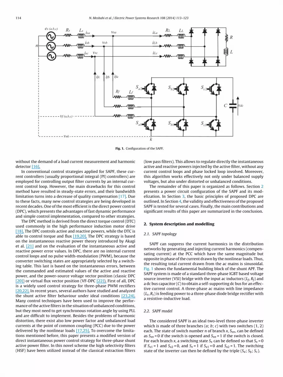
114 N. Mesbahi et al. / Electric Power Systems Research 108 (2014) 113– 123
R
L
RL LLRs Ls
Rf Lf
vsa
vsb
vsc
es (a ,b,c)isa
isb
isc
iLa
iLb
iLc
ifaifbifc
C vdc
n
vf (a ,b,c)
vnk
1aS
2aS
1bS1cS
2bS 2cS
k
uratio
wd
rermltr(a
u[aoerccitp[i[tMmbadcdtda(
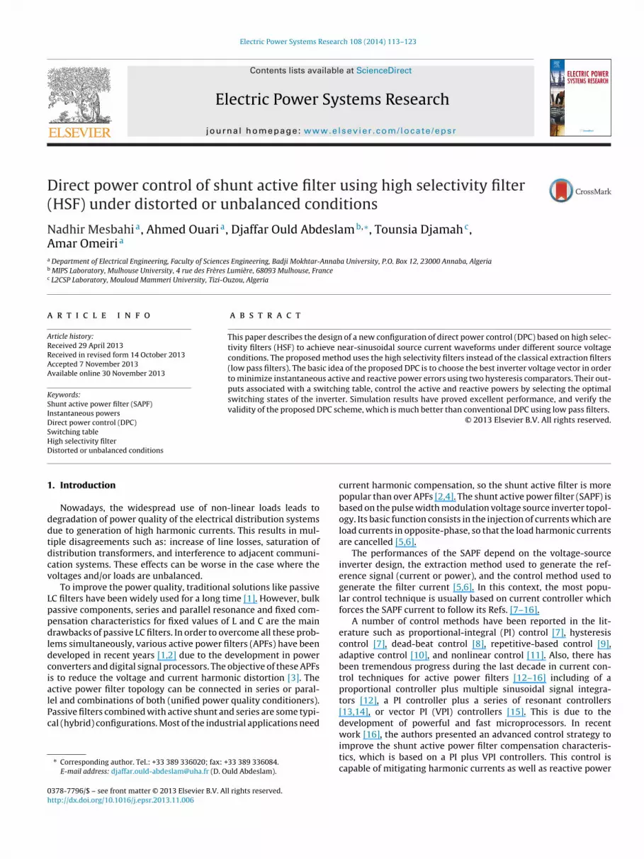
Fig. 1. Config
ithout the demand of a load current measurement and harmonicetector [16].
In conventional control strategies applied for SAPF, these cur-ent controllers (usually proportional integral (PI) controllers) aremployed for controlling output filter currents by an internal cur-ent control loop. However, the main drawbacks for this controlethod have resulted in steady-state errors, and their bandwidth
imitation turns into a decrease of quality compensation [17]. Dueo these facts, many new control strategies are being developed inecent decades. One of the most efficient is the direct power controlDPC), which presents the advantages of fast dynamic performancend simple control implementation, compared to other strategies.
The DPC method is derived from the direct torque control (DTC)sed commonly in the high performance induction motor drive18]. The DPC controls active and reactive powers, while the DTC isble to control torque and flux [19,20]. The DPC strategy is basedn the instantaneous reactive power theory introduced by Akagit al. [21] and on the evaluation of the instantaneous active andeactive power error values. In DPC, there are no internal currentontrol loops and no pulse width-modulation (PWM), because theonverter switching states are appropriately selected by a switch-ng table. This last is based on the instantaneous errors, betweenhe commanded and estimated values of the active and reactiveower, and the power-source voltage vector position (classic DPC20]) or virtual flux vector position (VF-DPC [22]). First of all, DPCs a widely used control strategy for three-phase PWM rectifiers20,22]. In recent years, several authors have studied and analyzedhe shunt active filter behaviour under ideal conditions [23,24].
any control techniques have been used to improve the perfor-ance of the active filters in the situation of unbalanced conditions,
ut they most need to get synchronous rotation angle by using PLLnd are difficult to implement. Besides the problems of harmonicistortion, there exist also low power factor and unbalanced loadurrents at the point of common coupling (PCC) due to the powerelivered by the nonlinear loads [17,25]. To overcome the limita-
ions mentioned before, this paper presents a modified version ofirect instantaneous power control strategy for three-phase shuntctive power filter. In this novel scheme the high selectivity filtersHSF) have been utilized instead of the classical extraction filtersn of the SAPF.
(low pass filters). This allows to regulate directly the instantaneousactive and reactive powers injected by the active filter, without anycurrent control loops and phase locked loop involved. Moreover,this algorithm works effectively not only under balanced supplyvoltages, but also under distorted or unbalanced conditions.
The remainder of this paper is organized as follows. Section 2presents a power circuit configuration of the SAPF and its mod-elization. In Section 3, the basic principles of proposed DPC areoutlined. In Section 4, the validity and effectiveness of the proposedSAPF is tested for several cases. Finally, the main contributions andsignificant results of this paper are summarized in the conclusion.
2. System description and modelling
2.1. SAPF topology
SAPF can suppress the current harmonics in the distributionnetworks by generating and injecting current harmonics (compen-sating current) at the PCC which have the same magnitude butopposite in phase of the current drawn by the nonlinear loads. Thus,the resulting total current drawn from the ac mains is sinusoidal.Fig. 1 shows the fundamental building block of the shunt APF. TheSAPF system is made of a standard three-phase IGBT based voltagesource inverter (VSI) bridge with the input ac inductors (Lf, Rf) anda dc bus capacitor (C) to obtain a self-supporting dc bus for an effec-tive current control. A three-phase ac mains with line impedance(Ls, Rs) is feeding power to a three-phase diode bridge rectifier witha resistive-inductive load.
2.2. SAPF model
The considered SAPF is an ideal two-level three-phase inverterwhich is made of three branches (a; b; c) with two switches (1, 2)each. The state of switch number n of branch x, Sxn, can be defined
as Sxn = 0 if the switch is opened and Sxn = 1 if the switch is closed.For each branch x, a switching state Sx can be defined so that Sx = 0if Sx1 = 1 and Sx2 = 0, and Sx = 1 if Sx1 = 0 and Sx2 = 1. The switchingstate of the inverter can then be defined by the triple (Sa; Sb; Sc).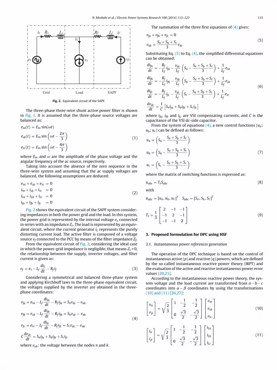
N. Mesbahi et al. / Electric Power System
Lisi sR sL fifR fL
se fvsv
ib
wa
tb
itiads
itc
v
atp
w
⎡ ⎤⎡ ⎤
Grid SAPFLoad
Fig. 2. Equivalent circuit of the SAPF.
The three-phase three-wire shunt active power filter is shownn Fig. 1. It is assumed that the three-phase source voltages arealanced as:
esa(t) = Em sin(ωt)
esb(t) = Em sin(
ωt − 2�
3
)esc(t) = Em sin
(ωt − 4�
3
) (1)
here Em and ω are the amplitude of the phase voltage and thengular frequency of the ac source, respectively.
Taking into account the absence of the zero sequence in thehree-wire system and assuming that the ac supply voltages arealanced, the following assumptions are deduced:
esa + esb + esc = 0
isa + isb + isc = 0
iLa + iLb + iLc = 0
ifa + ifb + ifc = 0
(2)
Fig. 2 shows the equivalent circuit of the SAPF system consider-ng impedances in both the power grid and the load. In this system,he power grid is represented by the internal voltage es connectedn series with an impedance Zs. The load is represented by an equiv-lent circuit, where the current generator iL represents the purelyistorting current load. The active filter is composed of a voltageource vf connected to the PCC by means of the filter impedance Zf.
From the equivalent circuit of Fig. 2, considering the ideal casen which the power-grid impedance is negligible, that means Zs = 0,he relationship between the supply, inverter voltages, and filterurrent is given as:
f = es − Lfdifdt
− Rf if (3)
Considering a symmetrical and balanced three-phase systemnd applying Kirchhoff laws to the three-phase equivalent circuit,he voltages supplied by the inverter are obtained in the three-hase coordinates:
vfa = esa − Lfdifadt
− Rf ifa = Savdc − vnk
vfb = esb − Lfdifbdt
− Rf ifb = Sbvdc − vnk
vfc = esc − Lfdifc − Rf ifc = Scvdc − vnk
(4)
dt
Cdvdc
dt= Saifa + Sbifb + Scifc
here vnk: the voltage between the nodes n and k.
s Research 108 (2014) 113– 123 115
The summation of the three first equations of (4) gives:
vfa + vfb + vfc = 0
vnk = Sa + Sb + Sc
3vdc
(5)
Substituting Eq. (5) to Eq. (4), the simplified differential equationscan be obtained:
difadt
= −Rf
Lfifa − vdc
Lf
(Sa − Sa + Sb + Sc
3
)+ 1
Lfesa
difbdt
= −Rf
Lfifb − vdc
Lf
(Sb − Sa + Sb + Sc
3
)+ 1
Lfesb
difcdt
= −Rf
Lfifc − vdc
Lf
(Sc − Sa + Sb + Sc
3
)+ 1
Lfesc
dvdc
dt= 1
C
[Saifa + Sbifb + Scifc
](6)
where ifa, ifb and ifc are VSI compensating currents, and C is thecapacitance of the VSI dc-side capacitor.
From the system of equations (4), a new control functions (ua;ub; uc) can be defined as follows:
ua =(
Sa − Sa + Sb + Sc
3
)ub =
(Sb − Sa + Sb + Sc
3
)uc =
(Sc − Sa + Sb + Sc
3
)(7)
where the matrix of switching functions is expressed as:
uabc = TsSabc (8)
with
uabc = [ua, ub, uc]T Sabc = [Sa, Sb, Sc]T
Ts = 13
⎡⎣ 2 −1 −1
−1 2 −1
−1 −1 2
⎤⎦ (9)
3. Proposed formulation for DPC using HSF
3.1. Instantaneous power references generation
The operation of the DPC technique is based on the control ofinstantaneous active (p) and reactive (q) powers, which are definedby the so-called instantaneous reactive power theory (IRPT) andthe evaluation of the active and reactive instantaneous power errorvalues [20,21].
According to the instantaneous reactive power theory, the sys-tem voltage and the load current are transformed from a − b − ccoordinates into − coordinates by using the transformations(10) and (11) [26,27]:
[v˛
vˇ
]=
√23
⎡⎢⎣ 1 −1
2−1
2
0
√3
2−
√3
2
⎤⎥⎦
⎡⎢⎣
vsa
vsb
vsc
⎤⎥⎦ (10)
[ia
iˇ
]=
√23
⎢⎣ 1 −12
−12
0
√3
2−
√3
2
⎥⎦⎢⎣iLa
iLb
iLc
⎥⎦ (11)
116 N. Mesbahi et al. / Electric Power Systems Research 108 (2014) 113– 123
abc αβ
p & qcalculation
-
abc αβ
dcv
dc volt age
controll er +
-∗dcv
refpLabci
sabcv
+LPF +
-
refqLPF
+-
(a)
HSF abc
αβ p & qcalculation
+++
+
-
-
HSF abc
αβ
αhiβhi
αiβi
αvβv
dcv
dc volt age
controller +
-∗dcv
refp
refq
Labci
sabcv
(b)
FL
t
p
f[
wTtltatat(Hctpoddsc
+
-
s1
-
+
+
+
s1+
-
K
K
cω
cω
αX
βX
αX
βX
errors between reference and actual values in each sampling step.
ig. 3. Block diagram of the power references generation: (a) conventional basedPF and (b) proposed based HSF.
In fact, instantaneous real power (p) is equal to following equa-ion:
= vsaiLa + vsbiLb + vsciLc (12)
The possibility of calculating them from − coordinates, asollows:
p
q
]=
[v˛ vˇ
−vˇ v˛
] [i˛
iˇ
](13)
The instantaneous power p can be decomposed to p = p + p,ith p the continuous component and p the harmonic component.
he dc and ac components in these instantaneous active and reac-ive powers are due to fundamental and harmonic currents of theoad, respectively. The power values of the dc components are fil-ered out by two low-pass filters (LPF) or high pass filters (HPF)s described in Fig. 3a. However, the instantaneous reactive powerheory, in its standard form, does not allow to work under unbal-nced conditions. In this paper, we propose a new method forhe computation of instantaneous power reference based on HSFsFig. 3b), so the power reference can be calculated. By using theSF filter, one can operate under any distorted and/or unbalancedonditions. On the other hand, the obtained instantaneous powererms in this method are the instantaneous active power referenceref and the instantaneous reactive power reference qref. The firstne is generated based on the instantaneous active power ripplesrawn by the nonlinear load, plus the power requirement of the
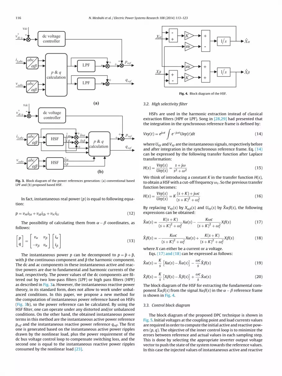
c bus voltage control loop to compensate switching loss, and theecond one is equal to the instantaneous reactive power ripplesonsumed by the nonlinear load [23].Fig. 4. Block diagram of the HSF.
3.2. High selectivity filter
HSFs are used in the harmonic extraction instead of classicalextraction filters (HPF or LPF). Song in [28,29] had presented thatthe integration in the synchronous reference frame is defined by:
Vxy(t) = ejωt
∫e−jωtUxy(t)dt (14)
where Uxy and Vxy are the instantaneous signals, respectively beforeand after integration in the synchronous reference frame. Eq. (14)can be expressed by the following transfer function after Laplacetransformation:
H(s) = Vxy(s)Uxy(s)
= s + jω
s2 + ω2(15)
We think of introducing a constant K in the transfer function H(s),to obtain a HSF with a cut-off frequency ωc. So the previous transferfunction becomes:
H(s) = Vxy(s)Uxy(s)
= K(s + K) + jωc
(s + K)2 + ω2c
(16)
By replacing Vxy(s) by X˛ˇ(s) and Uxy(s) by X˛ˇ(s), the followingexpressions can be obtained:
X˛(s) = K(s + K)
(s + K)2 + ω2c
X˛(s) − Kωc
(s + K)2 + ω2c
Xˇ(s) (17)
Xˇ(s) = − Kωc
(s + K)2 + ω2c
X˛(s) + K(s + K)
(s + K)2 + ω2c
Xˇ(s) (18)
where X can either be a current or a voltage.Eqs. (17) and (18) can be expressed as follows:
X˛(s) = K
s
[X˛(s) − X˛(s)
]− ωc
sXˇ(s) (19)
Xˇ(s) = K
s
[Xˇ(s) − Xˇ(s)
]+ ωc
sX˛(s) (20)
The block diagram of the HSF for extracting the fundamental com-ponent X˛ˇ(s) from the signal X˛ˇ(s) in the − reference frameis shown in Fig. 4.
3.3. Control block diagram
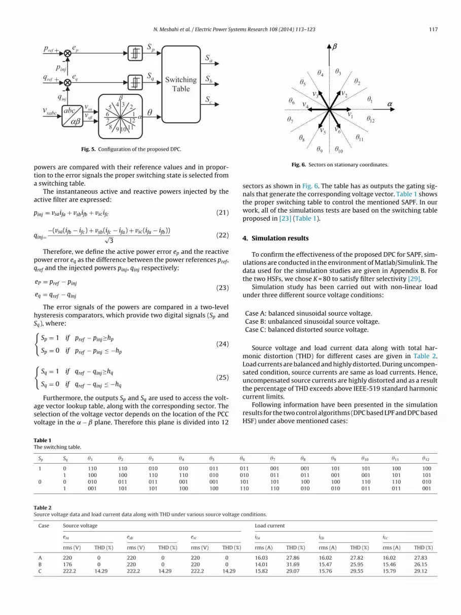
The block diagram of the proposed DPC technique is shown inFig. 5. Initial voltages at the coupling point and load currents valuesare required in order to compute the initial active and reactive pow-ers (p, q). The objective of the inner control loop is to minimize the
This is done by selecting the appropriate inverter output voltagevector to push the state of the system towards the reference values.In this case the injected values of instantaneous active and reactive
N. Mesbahi et al. / Electric Power Systems Research 108 (2014) 113– 123 117
pS
qS
θ
aS
bS
cS
Switching
Table
sabcv abc αβ
1
2345678 9 10 11
12 α
β
injp
refp +
-
injq
refq +
-
sαvsβv
pe
qe
pta
a
p
q
pq
hS{
{
asv
1θ
2θ3θ
12θ
11θ
10θ9θ8θ
6θ
4θ5θ
7θ 1v
2v3v
4v
5v 6v
αα
ββ
TT
TS
Fig. 5. Configuration of the proposed DPC.
owers are compared with their reference values and in propor-ion to the error signals the proper switching state is selected from
switching table.The instantaneous active and reactive powers injected by the
ctive filter are expressed:
inj = vsaifa + vsbifb + vscifc (21)
inj=−(vsa(ifb − ifc) + vsb(ifc − ifa) + vsc(ifa − ifb))√
3(22)
Therefore, we define the active power error ep and the reactiveower error eq as the difference between the power references pref,ref and the injected powers pinj, qinj respectively:
eP = pref − pinj
eq = qref − qinj
(23)
The error signals of the powers are compared in a two-levelysteresis comparators, which provide two digital signals (Sp andq), where:
Sp = 1 if pref − pinj≥hp
Sp = 0 if pref − pinj ≤ −hp
(24)
Sq = 1 if qref − qinj≥hq
Sq = 0 if qref − qinj ≤ −hq
(25)
Furthermore, the outputs Sp and Sq are used to access the volt-ge vector lookup table, along with the corresponding sector. Theelection of the voltage vector depends on the location of the PCColtage in the − plane. Therefore this plane is divided into 12
able 1he switching table.
Sp Sq �1 �2 �3 �4 �5 �
1 0 110 110 010 010 011 01 100 100 110 110 010 0
0 0 010 011 011 001 001 11 001 101 101 100 100 1
able 2ource voltage data and load current data along with THD under various source voltage c
Case Source voltage
esa esb esc
rms (V) THD (%) rms (V) THD (%) rms (V) THD (%)
A 220 0 220 0 220 0
B 176 0 220 0 220 0
C 222.2 14.29 222.2 14.29 222.2 14.29
Fig. 6. Sectors on stationary coordinates.
sectors as shown in Fig. 6. The table has as outputs the gating sig-nals that generate the corresponding voltage vector. Table 1 showsthe proper switching table to control the mentioned SAPF. In ourwork, all of the simulations tests are based on the switching tableproposed in [23] (Table 1).
4. Simulation results
To confirm the effectiveness of the proposed DPC for SAPF, sim-ulations are conducted in the environment of Matlab/Simulink. Thedata used for the simulation studies are given in Appendix B. Forthe two HSFs, we chose K = 80 to satisfy filter selectivity [29].
Simulation study has been carried out with non-linear loadunder three different source voltage conditions:
Case A: balanced sinusoidal source voltage.Case B: unbalanced sinusoidal source voltage.Case C: balanced distorted source voltage.
Source voltage and load current data along with total har-monic distortion (THD) for different cases are given in Table 2.Load currents are balanced and highly distorted. During uncompen-sated condition, source currents are same as load currents. Hence,uncompensated source currents are highly distorted and as a resultthe percentage of THD exceeds above IEEE-519 standard harmoniccurrent limits.
Following information have been presented in the simulationresults for the two control algorithms (DPC based LPF and DPC basedHSF) under above mentioned cases:
6 �7 �8 �9 �10 �11 �12
11 001 001 101 101 100 10010 011 011 001 001 101 10101 101 100 100 110 110 01010 110 010 010 011 011 001
onditions.
Load current
iLa iLb iLc
rms (A) THD (%) rms (A) THD (%) rms (A) THD (%)
16.03 27.86 16.02 27.82 16.02 27.8314.01 31.69 15.47 25.95 15.46 26.1515.82 29.07 15.76 29.55 15.79 29.12
118 N. Mesbahi et al. / Electric Power Systems Research 108 (2014) 113– 123
0.04 0.05 0.06 0.07 0.08 0.09 0.1 0.11 0.12-400
-300
-200
-100
0
100
200
300
400
Time (s)
esa
bc (V
)
0 2 4 6 8 10 12 14 16 18 200
50
100
150
200
250
300
350
Harmonic order
0.04 0.05 0.06 0.07 0.08 0.09 0.1 0.11 0.12-25
-20
-15
-10
-5
0
5
10
15
20
25
Time (s)
iLabc (A
)
0 2 4 6 8 10 12 14 16 18 200
5
10
15
20
25
Harmonic order
0.04 0.05 0.06 0.07 0.08 0.09 0.1 0.11 0.12-25
-20
-15
-10
-5
0
5
10
15
20
25
Time (s)
isabc (A
)
0 2 4 6 8 10 12 14 16 18 200
5
10
15
20
25
Harmonic or der
0.04 0.05 0.06 0.07 0.08 0.09 0.1 0.11 0.12-25
-20
-15
-10
-5
0
5
10
15
20
25
Time (s)
isabc (A
)
0 2 4 6 8 10 12 14 16 18 200
5
10
15
20
25
Harmonic order
0.04 0.05 0.06 0.07 0.08 0.09 0.1 0.11 0.12-25
-20
-15
-10
-5
0
5
10
15
20
25
ifa (A
)
Time (s)
0.04 0.05 0.06 0.07 0.08 0.09 0.1 0.11 0.12-25
-20
-15
-10
-5
0
5
10
15
20
25
Time (s)
ifa (A
)
0.04 0.05 0.06 0.07 0.08 0.09 0.1 0.11 0.12-40
-30
-20
-10
0
10
20
30
40
Time (s)
esa
(V
) &
isa
(A
)
esa/10
0.04 0.05 0.06 0.07 0.08 0.09 0.1 0.11 0.12-40
-30
-20
-10
0
10
20
30
40
Time (s)
esa
(V
) &
isa
(A
)
esa/10
(i)
(ii)
(ii i)
(iv)
(v)
(vi)
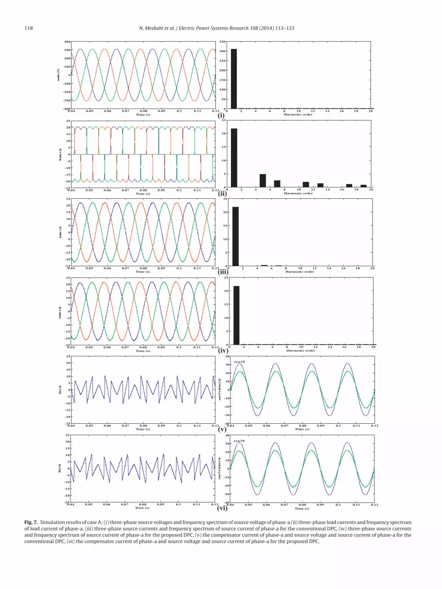
Fig. 7. Simulation results of case A: (i) three-phase source voltages and frequency spectrum of source voltage of phase-a (ii) three-phase load currents and frequency spectrumof load current of phase-a, (iii) three-phase source currents and frequency spectrum of source current of phase-a for the conventional DPC, (iv) three-phase source currentsand frequency spectrum of source current of phase-a for the proposed DPC, (v) the compensator current of phase-a and source voltage and source current of phase-a for theconventional DPC, (vi) the compensator current of phase-a and source voltage and source current of phase-a for the proposed DPC.
N. Mesbahi et al. / Electric Power Systems Research 108 (2014) 113– 123 119
0.04 0.05 0.06 0.07 0.08 0.09 0.1 0.11 0.12790
792
794
796
798
800
802
804
806
808
810
Tim
vd
c (
V)
apacit
(
(
(
s
4
basmtacFusv
4
mossfmgiTagcm
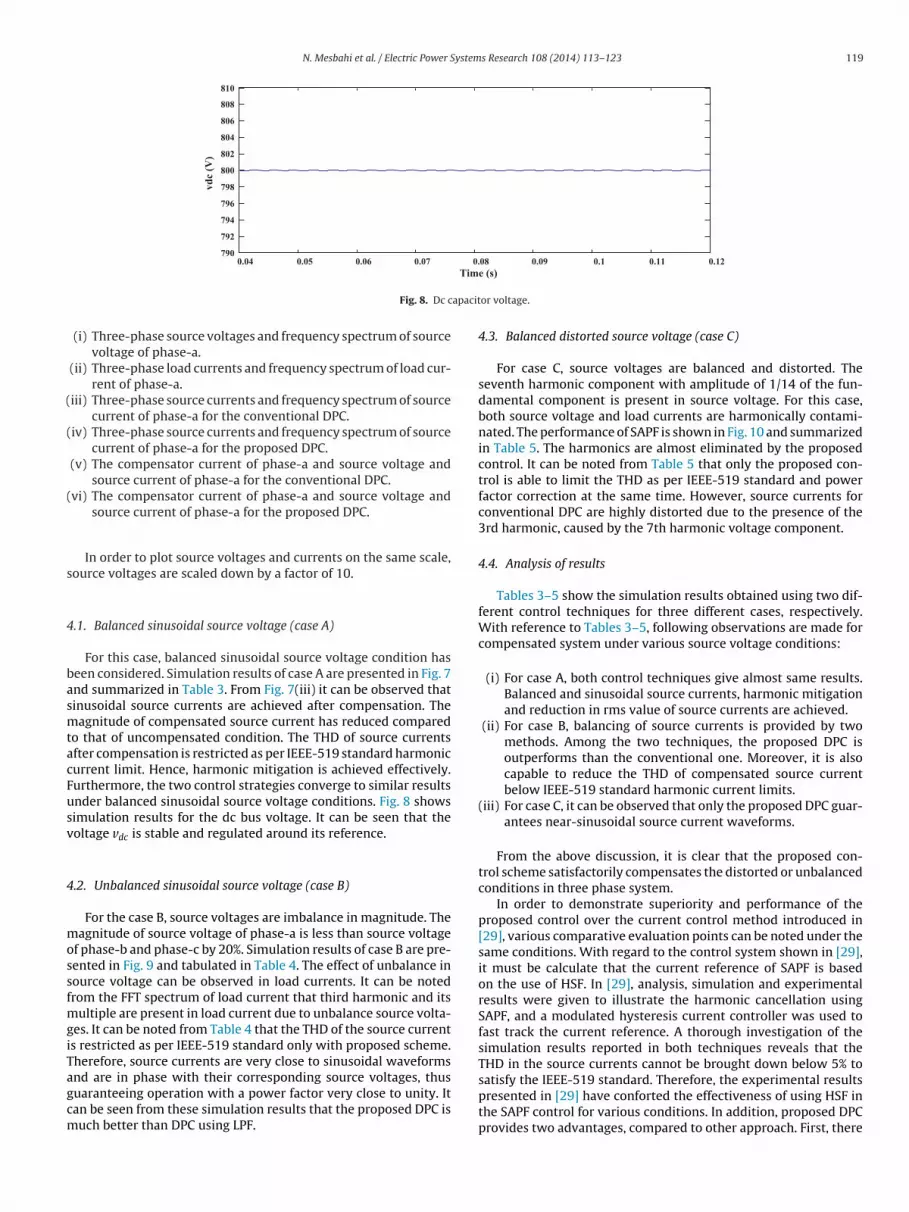
Fig. 8. Dc c
(i) Three-phase source voltages and frequency spectrum of sourcevoltage of phase-a.
(ii) Three-phase load currents and frequency spectrum of load cur-rent of phase-a.
iii) Three-phase source currents and frequency spectrum of sourcecurrent of phase-a for the conventional DPC.
iv) Three-phase source currents and frequency spectrum of sourcecurrent of phase-a for the proposed DPC.
(v) The compensator current of phase-a and source voltage andsource current of phase-a for the conventional DPC.
vi) The compensator current of phase-a and source voltage andsource current of phase-a for the proposed DPC.
In order to plot source voltages and currents on the same scale,ource voltages are scaled down by a factor of 10.
.1. Balanced sinusoidal source voltage (case A)
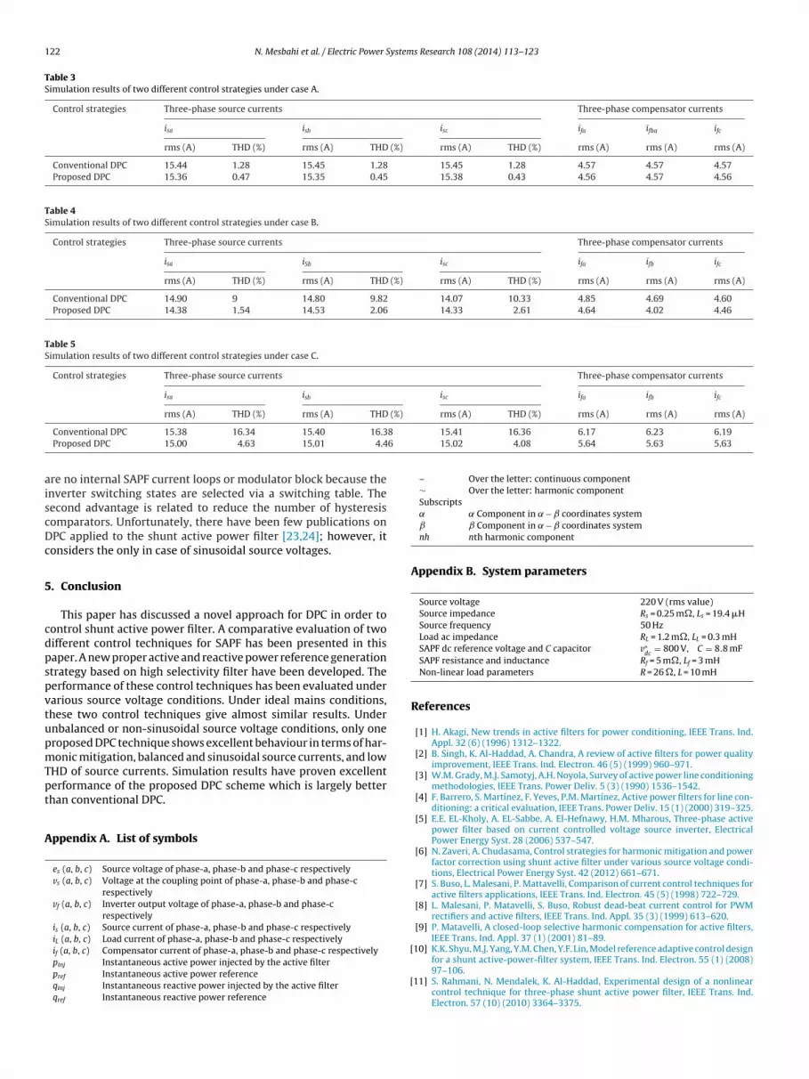
For this case, balanced sinusoidal source voltage condition haseen considered. Simulation results of case A are presented in Fig. 7nd summarized in Table 3. From Fig. 7(iii) it can be observed thatinusoidal source currents are achieved after compensation. Theagnitude of compensated source current has reduced compared
o that of uncompensated condition. The THD of source currentsfter compensation is restricted as per IEEE-519 standard harmonicurrent limit. Hence, harmonic mitigation is achieved effectively.urthermore, the two control strategies converge to similar resultsnder balanced sinusoidal source voltage conditions. Fig. 8 showsimulation results for the dc bus voltage. It can be seen that theoltage vdc is stable and regulated around its reference.
.2. Unbalanced sinusoidal source voltage (case B)
For the case B, source voltages are imbalance in magnitude. Theagnitude of source voltage of phase-a is less than source voltage
f phase-b and phase-c by 20%. Simulation results of case B are pre-ented in Fig. 9 and tabulated in Table 4. The effect of unbalance inource voltage can be observed in load currents. It can be notedrom the FFT spectrum of load current that third harmonic and its
ultiple are present in load current due to unbalance source volta-es. It can be noted from Table 4 that the THD of the source currents restricted as per IEEE-519 standard only with proposed scheme.herefore, source currents are very close to sinusoidal waveforms
nd are in phase with their corresponding source voltages, thusuaranteeing operation with a power factor very close to unity. Itan be seen from these simulation results that the proposed DPC isuch better than DPC using LPF.e (s)
or voltage.
4.3. Balanced distorted source voltage (case C)
For case C, source voltages are balanced and distorted. Theseventh harmonic component with amplitude of 1/14 of the fun-damental component is present in source voltage. For this case,both source voltage and load currents are harmonically contami-nated. The performance of SAPF is shown in Fig. 10 and summarizedin Table 5. The harmonics are almost eliminated by the proposedcontrol. It can be noted from Table 5 that only the proposed con-trol is able to limit the THD as per IEEE-519 standard and powerfactor correction at the same time. However, source currents forconventional DPC are highly distorted due to the presence of the3rd harmonic, caused by the 7th harmonic voltage component.
4.4. Analysis of results
Tables 3–5 show the simulation results obtained using two dif-ferent control techniques for three different cases, respectively.With reference to Tables 3–5, following observations are made forcompensated system under various source voltage conditions:
(i) For case A, both control techniques give almost same results.Balanced and sinusoidal source currents, harmonic mitigationand reduction in rms value of source currents are achieved.
(ii) For case B, balancing of source currents is provided by twomethods. Among the two techniques, the proposed DPC isoutperforms than the conventional one. Moreover, it is alsocapable to reduce the THD of compensated source currentbelow IEEE-519 standard harmonic current limits.
(iii) For case C, it can be observed that only the proposed DPC guar-antees near-sinusoidal source current waveforms.
From the above discussion, it is clear that the proposed con-trol scheme satisfactorily compensates the distorted or unbalancedconditions in three phase system.
In order to demonstrate superiority and performance of theproposed control over the current control method introduced in[29], various comparative evaluation points can be noted under thesame conditions. With regard to the control system shown in [29],it must be calculate that the current reference of SAPF is basedon the use of HSF. In [29], analysis, simulation and experimentalresults were given to illustrate the harmonic cancellation usingSAPF, and a modulated hysteresis current controller was used tofast track the current reference. A thorough investigation of thesimulation results reported in both techniques reveals that theTHD in the source currents cannot be brought down below 5% to
satisfy the IEEE-519 standard. Therefore, the experimental resultspresented in [29] have conforted the effectiveness of using HSF inthe SAPF control for various conditions. In addition, proposed DPCprovides two advantages, compared to other approach. First, there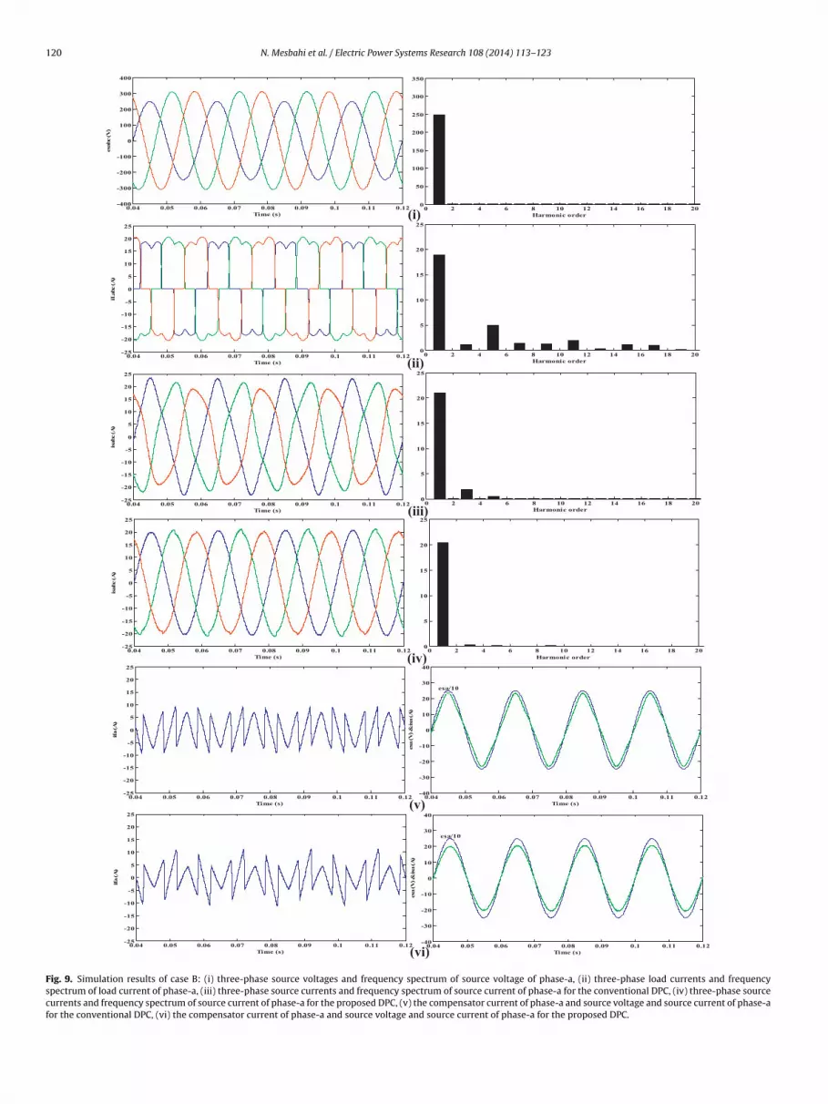
120 N. Mesbahi et al. / Electric Power Systems Research 108 (2014) 113– 123
0.04 0.05 0.06 0.07 0.08 0.09 0.1 0.11 0.12-400
-300
-200
-100
0
100
200
300
400
Time (s)
esa
bc (V
)
0 2 4 6 8 10 12 14 16 18 200
50
100
150
200
250
300
350
Harmonic order
0.04 0.05 0.06 0.07 0.08 0.09 0.1 0.11 0.12-25
-20
-15
-10
-5
0
5
10
15
20
25
Time (s)
iLabc (A
)
0 2 4 6 8 10 12 14 16 18 200
5
10
15
20
25
Harmonic order
0 2 4 6 8 10 12 14 16 18 200
5
10
15
20
25
Harmonic order
0.04 0.05 0.06 0.07 0.08 0.09 0.1 0.11 0.12-25
-20
-15
-10
-5
0
5
10
15
20
25
Time (s)
isabc (A
)
0.04 0.05 0.06 0.07 0.08 0.09 0.1 0.11 0.12-25
-20
-15
-10
-5
0
5
10
15
20
25
Time (s)
ifa (A
)
0.04 0.05 0.06 0.07 0.08 0.09 0.1 0.11 0.12-40
-30
-20
-10
0
10
20
30
40
Time (s)
esa
(V
) &
isa
(A
)
esa/10
0.04 0.05 0.06 0.07 0.08 0.09 0.1 0.11 0.12-40
-30
-20
-10
0
10
20
30
40
Time (s)
esa
(V
) &
isa
(A
)
esa/10
0.04 0.05 0.06 0.07 0.08 0.09 0.1 0.11 0.12-25
-20
-15
-10
-5
0
5
10
15
20
25
Time (s)
ifa (A
)
0.04 0.05 0.06 0.07 0.08 0.09 0.1 0.11 0.12-25
-20
-15
-10
-5
0
5
10
15
20
25
Time (s)
isabc (A
)
0 2 4 6 8 10 12 14 16 18 200
5
10
15
20
25
Harmonic or der
(i)
(ii)
(ii i)
(iv)
(v)
(vi)
Fig. 9. Simulation results of case B: (i) three-phase source voltages and frequency spectrum of source voltage of phase-a, (ii) three-phase load currents and frequencyspectrum of load current of phase-a, (iii) three-phase source currents and frequency spectrum of source current of phase-a for the conventional DPC, (iv) three-phase sourcecurrents and frequency spectrum of source current of phase-a for the proposed DPC, (v) the compensator current of phase-a and source voltage and source current of phase-afor the conventional DPC, (vi) the compensator current of phase-a and source voltage and source current of phase-a for the proposed DPC.

N. Mesbahi et al. / Electric Power Systems Research 108 (2014) 113– 123 121
0.04 0.05 0.06 0.07 0.08 0.09 0.1 0.11 0.12-400
-300
-200
-100
0
100
200
300
400
Time (s)
esa
bc (V
)
0 2 4 6 8 10 12 14 16 18 200
50
100
150
200
250
300
350
Harmonic or der
0.04 0.05 0.06 0.07 0.08 0.09 0.1 0.11 0.12-25
-20
-15
-10
-5
0
5
10
15
20
25
Time (s)
iLabc (A
)
0 2 4 6 8 10 12 14 16 18 200
5
10
15
20
25
Harmonic or der
0.04 0.05 0.06 0.07 0.08 0.09 0.1 0.11 0.12-30
-20
-10
0
10
20
30
Time (s)
isabc (A
)
0 2 4 6 8 10 12 14 16 18 200
5
10
15
20
25
Harmonic or der
0.04 0.05 0.06 0.07 0.08 0.09 0.1 0.11 0.12-25
-20
-15
-10
-5
0
5
10
15
20
25
Time (s)
ifa (A
)
0.04 0.05 0.06 0.07 0.08 0.09 0.1 0.11 0.12-40
-30
-20
-10
0
10
20
30
40
Time (s)
esa
(V
) &
isa
(A
)
esa/10
0.04 0.05 0.06 0.07 0.08 0.09 0.1 0.11 0.12-30
-20
-10
0
10
20
30
Time (s)
isabc (A
)
0 2 4 6 8 10 12 14 16 18 200
5
10
15
20
25
Harmonic or der
0.04 0.05 0.06 0.07 0.08 0.09 0.1 0.11 0.12-25
-20
-15
-10
-5
0
5
10
15
20
25
Time (s)
ifa (A)
0.04 0.05 0.06 0.07 0.08 0.09 0.1 0.11 0.12-40
-30
-20
-10
0
10
20
30
40
Time (s)
esa
(V
) &
isa
(A)
(i)
(ii)
(ii i)
(iv)
(v)
(vi)
Fig. 10. Simulation results of case C: (i) three-phase source voltages and frequency spectrum of source voltage of phase-a, (ii) three-phase load currents and frequencyspectrum of load current of phase-a, (iii) three-phase source currents and frequency spectrum of source current of phase-a for the conventional DPC, (iv) three-phase sourcecurrents and frequency spectrum of source current of phase-a for the proposed DPC, (v) The compensator current of phase-a and source voltage and source current of phase-afor the conventional DPC, (vi) the compensator current of phase-a and source voltage and source current of phase-a for the proposed DPC.
122 N. Mesbahi et al. / Electric Power Systems Research 108 (2014) 113– 123
Table 3Simulation results of two different control strategies under case A.
Control strategies Three-phase source currents Three-phase compensator currents
isa isb isc ifa ifba ifc
rms (A) THD (%) rms (A) THD (%) rms (A) THD (%) rms (A) rms (A) rms (A)
Conventional DPC 15.44 1.28 15.45 1.28 15.45 1.28 4.57 4.57 4.57Proposed DPC 15.36 0.47 15.35 0.45 15.38 0.43 4.56 4.57 4.56
Table 4Simulation results of two different control strategies under case B.
Control strategies Three-phase source currents Three-phase compensator currents
isa iSb isc ifa ifb ifc
rms (A) THD (%) rms (A) THD (%) rms (A) THD (%) rms (A) rms (A) rms (A)
Conventional DPC 14.90 9 14.80 9.82 14.07 10.33 4.85 4.69 4.60Proposed DPC 14.38 1.54 14.53 2.06 14.33 2.61 4.64 4.02 4.46
Table 5Simulation results of two different control strategies under case C.
Control strategies Three-phase source currents Three-phase compensator currents
isa isb isc ifa ifb ifc
rms (A) THD (%) rms (A) THD (%) rms (A) THD (%) rms (A) rms (A) rms (A)
8
6
aiscDc
5
cdpspvtupmTpt
A
[
Conventional DPC 15.38 16.34 15.40 16.3Proposed DPC 15.00 4.63 15.01 4.4
re no internal SAPF current loops or modulator block because thenverter switching states are selected via a switching table. Theecond advantage is related to reduce the number of hysteresisomparators. Unfortunately, there have been few publications onPC applied to the shunt active power filter [23,24]; however, itonsiders the only in case of sinusoidal source voltages.
. Conclusion
This paper has discussed a novel approach for DPC in order toontrol shunt active power filter. A comparative evaluation of twoifferent control techniques for SAPF has been presented in thisaper. A new proper active and reactive power reference generationtrategy based on high selectivity filter have been developed. Theerformance of these control techniques has been evaluated underarious source voltage conditions. Under ideal mains conditions,hese two control techniques give almost similar results. Undernbalanced or non-sinusoidal source voltage conditions, only oneroposed DPC technique shows excellent behaviour in terms of har-onic mitigation, balanced and sinusoidal source currents, and low
HD of source currents. Simulation results have proven excellenterformance of the proposed DPC scheme which is largely betterhan conventional DPC.
ppendix A. List of symbols
es (a, b, c) Source voltage of phase-a, phase-b and phase-c respectivelyvs (a, b, c) Voltage at the coupling point of phase-a, phase-b and phase-c
respectivelyvf (a, b, c) Inverter output voltage of phase-a, phase-b and phase-c
respectivelyis (a, b, c) Source current of phase-a, phase-b and phase-c respectivelyiL (a, b, c) Load current of phase-a, phase-b and phase-c respectively
if (a, b, c) Compensator current of phase-a, phase-b and phase-c respectivelypinj Instantaneous active power injected by the active filterpref Instantaneous active power referenceqinj Instantaneous reactive power injected by the active filterqref Instantaneous reactive power reference[
15.41 16.36 6.17 6.23 6.1915.02 4.08 5.64 5.63 5.63
– Over the letter: continuous component∼ Over the letter: harmonic componentSubscripts˛ Component in − coordinates systemˇ Component in − coordinates systemnh nth harmonic component
Appendix B. System parameters
Source voltage 220 V (rms value)Source impedance Rs = 0.25 m�, Ls = 19.4 �HSource frequency 50 HzLoad ac impedance RL = 1.2 m�, LL = 0.3 mHSAPF dc reference voltage and C capacitor v∗
dc= 800 V, C = 8.8 mF
SAPF resistance and inductance Rf = 5 m�, Lf = 3 mHNon-linear load parameters R = 26 �, L = 10 mH
References
[1] H. Akagi, New trends in active filters for power conditioning, IEEE Trans. Ind.Appl. 32 (6) (1996) 1312–1322.
[2] B. Singh, K. Al-Haddad, A. Chandra, A review of active filters for power qualityimprovement, IEEE Trans. Ind. Electron. 46 (5) (1999) 960–971.
[3] W.M. Grady, M.J. Samotyj, A.H. Noyola, Survey of active power line conditioningmethodologies, IEEE Trans. Power Deliv. 5 (3) (1990) 1536–1542.
[4] F. Barrero, S. Martínez, F. Yeves, P.M. Martínez, Active power filters for line con-ditioning: a critical evaluation, IEEE Trans. Power Deliv. 15 (1) (2000) 319–325.
[5] E.E. EL-Kholy, A. EL-Sabbe, A. El-Hefnawy, H.M. Mharous, Three-phase activepower filter based on current controlled voltage source inverter, ElectricalPower Energy Syst. 28 (2006) 537–547.
[6] N. Zaveri, A. Chudasama, Control strategies for harmonic mitigation and powerfactor correction using shunt active filter under various source voltage condi-tions, Electrical Power Energy Syst. 42 (2012) 661–671.
[7] S. Buso, L. Malesani, P. Mattavelli, Comparison of current control techniques foractive filters applications, IEEE Trans. Ind. Electron. 45 (5) (1998) 722–729.
[8] L. Malesani, P. Matavelli, S. Buso, Robust dead-beat current control for PWMrectifiers and active filters, IEEE Trans. Ind. Appl. 35 (3) (1999) 613–620.
[9] P. Matavelli, A closed-loop selective harmonic compensation for active filters,IEEE Trans. Ind. Appl. 37 (1) (2001) 81–89.
10] K.K. Shyu, M.J. Yang, Y.M. Chen, Y.F. Lin, Model reference adaptive control design
for a shunt active-power-filter system, IEEE Trans. Ind. Electron. 55 (1) (2008)97–106.11] S. Rahmani, N. Mendalek, K. Al-Haddad, Experimental design of a nonlinearcontrol technique for three-phase shunt active power filter, IEEE Trans. Ind.Electron. 57 (10) (2010) 3364–3375.
ystem
[
[
[
[
[
[
[
[
[
[
[
[
[
[
[
[
[
N. Mesbahi et al. / Electric Power S
12] R.I. Bojoi, G. Griva, V. Bostan, M. Guerriero, F. Farina, F. Profumo, Currentcontrol strategy for power conditioners using sinusoidal signal integratorsin synchronous reference frame, IEEE Trans. Power Electron. 20 (6) (2005)1402–1412.
13] C. Lascu, L. Asiminoaei, I. Boldea, F. Blaabjerg, Frequency response analysis ofcurrent controllers for selective harmonic compensation in active power filters,IEEE Trans. Ind. Electron. 56 (2) (2009) 337–347.
14] L. Limongi, R. Bojoi, G. Griva, A. Tenconi, Digital current-control schemes, IEEEInd. Electron. Mag. 3 (1) (2009) 20–31.
15] C. Lascu, L. Asiminoaei, I. Boldea, F. Blaabjerg, High performance current con-troller for selective harmonic compensation in active power filters, IEEE Trans.Power Electron. 22 (5) (2007) 1826–1835.
16] Q.N. Trinh, H.H. Lee, An advanced current control strategy for three-phase shunt active power filters, IEEE Trans. Ind. Electron. 60 (12) (2013)5400–5410.
17] R.L. de Araujo Ribeiro, C.C. de Azevedo, R.M. de Sousa, A robust adaptive controlstrategy of active power filters for power-factor correction, harmonic compen-sation, and balancing of nonlinear loads, IEEE Trans. Power Electron. 27 (2)(2012) 718–730.
18] Y. Lai, J. Lin, New hybrid fuzzy controller for direct torque control inductionmotor drives, IEEE Trans. Power Electron. 18 (5) (2003) 1211–1219.
19] M. Malinowski, M.P. Kazmierkowski, A.M. Trzynadlowski, A comparative study
of control techniques for PWM rectifiers in AC adjustable speed drives, IEEETrans. Power Electron. 18 (6) (2003) 1390–1396.20] T. Noguchi, H. Tomiki, S. Kondo, I. Takahashi, Direct power control of PWMconverter without power-source voltage sensors, IEEE Trans. Ind. Appl. 34 (3)(1998) 473–479.
[
s Research 108 (2014) 113– 123 123
21] H. Akagi, Y. Kanazawa, A. Nabae, Instantaneous reactive power compensatorscomprising switching devices without energy storage components, IEEE Trans.Ind. Appl. IA-20 (3) (1984) 625–630.
22] M. Malinowski, M.P. Kazmierkowski, S. Hansen, F. Blaabjerg, G.D. Marques,Virtual-flux-based direct power control of three phase PWM rectifiers, IEEETrans. Ind. Appl. 37 (4) (2001) 1019–1027.
23] B.S. Chen, G. Joós, Direct power control of active filters with averaged switchingfrequency regulation, IEEE Trans. Power Electron. 23 (6) (2008) 2729–2737.
24] A. Chaoui, F. Krim, J.P. Gaubert, L. Rambault, DPC controlled three-phase activefilter for power quality improvement, Electrical Power Energy Syst. 30 (2008)476–485.
25] T. Zaveri, B. Bhalja, N. Zaveri, Comparison of control strategies for DSTATCOMin three-phase, four-wire distribution system for power quality improvementunder various source voltage and load conditions, Electrical Power Energy Syst.43 (2012) 582–594.
26] L.S. Czarnecki, On some misinterpretations of the instantaneous reactive powerp − q theory, IEEE Trans. Power Electron. 19 (3) (2004) 828–836.
27] M.C. Benhabib, S. Saadate, New control approach for four-wire active powerfilter based on the use of synchronous reference frame, Electr. Power Syst. Res.73 (2005) 353–362.
28] H.-S. Song, H.-G. Park, K. Nam, An instantaneous phase angle detection algo-rithm under unbalanced line voltage condition, in: Proceedings of IEEE 30th
annual power electronics specialist conference, PESC’99, vol. 1, August, 1999,pp. 533–537.29] M. Abdusalam, P. Poure, S. Karimi, S. Saadate, New digital reference currentgeneration for shunt active power filter under distorted voltage conditions,Electr. Power Syst. Res. 79 (2009) 759–765.